Loading ...
Loading ...
Loading ...
AXISD2210-VERadar
Specifications
Note
ThePoEoutputisenabledwhentheradarispoweredbya60Wmidspan(PoweroverEthernetIEEE802.3bt,type3).
Note
Iftheradarispoweredbya30WmidspanorDCpower,thePoEoutisdisabled.
Note
MaximumEthernetcablelengthis100mintotalforPoEoutandPoEincombined.YoucanincreaseitwithaPoEextender.
Note
IftheconnectedPoEdevicerequiresmorethan30W,youcanadda60WmidspanbetweenthePoEoutportontheradar
andthedevice.ThemidspanwillpowerthedevicewhiletheradarwillprovidetheEthernetconnection.
I/Oconnector
UsetheI/Oconnectorwithexternaldevicesincombinationwith,forexample,eventtriggeringandalarmnotications.Inadditionto
the0VDCreferencepointandpower(DCoutput),theI/Oconnectorprovidestheinterfaceto:
Digitalinput-Forconnectingdevicesthatcantogglebetweenanopenandclosedcircuit,forexamplePIRsensors,door/window
contacts,andglassbreakdetectors.
Supervisedinput-Enablespossibilitytodetecttamperingonadigitalinput.
Digitaloutput-ForconnectingexternaldevicessuchasrelaysandLEDs.ConnecteddevicescanbeactivatedbytheVAPIX®
ApplicationProgrammingInterface,throughaneventorfromthedevice’swebinterface.
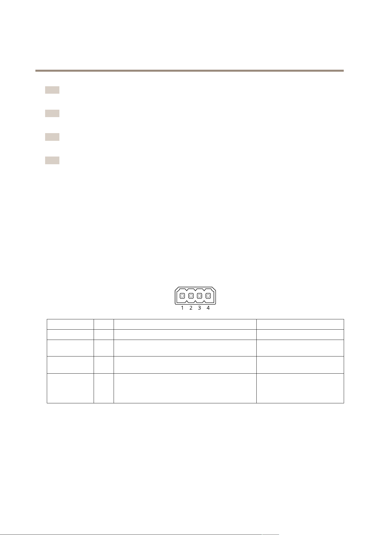
4-pinterminalblock
FunctionPinNotes
Specications
DCground
1
0VDC
DCoutput
2
Canbeusedtopowerauxiliaryequipment.
Note:Thispincanonlybeusedaspowerout.
12VDC
Maxload=25mA
DigitalInput
3
Connecttopin1toactivate,orleaveoating(unconnected)
todeactivate.
0tomax30VDC
DigitalOutput
4
Internallyconnectedtopin1(DCground)whenactive,
andoating(unconnected)wheninactive.Ifusedwithan
inductiveload,e.g.,arelay,connectadiodeinparallelwith
theload,toprotectagainstvoltagetransients.
0tomax30VDC,opendrain,
100mA
Example
65
Loading ...
Loading ...
Loading ...