Installation Bump-Out
Kit
Instructions
For 15” Deep Cabinets
BEFORE YOU BEGIN
Read these instructions completely and carefully.
IMPORTANT:
•
•
Save these instructions for local inspector’s use.
•
Observe all governing codes and ordinances.
• Note to Customer- Keep these instructions for future reference.
• Skill level- Installation of this appliance requires basic mechanical
and electrical skills.
•
Proper installation is the responsibility of the installer.
•
Product failure due to improper installation is not covered under
the Warranty.
Note to Installer – Be sure to leave these
instructions with the consumer.
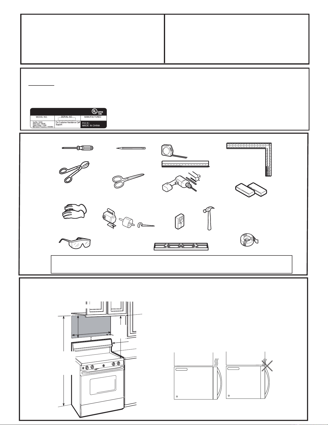
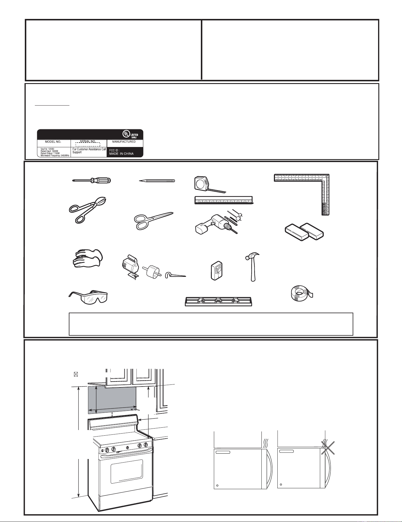
TOOLS YOU
WILL NEED
# 1 P hillips screwdriver
Pencil
Ruler or t ape measure and
straight edge
Carpenter square
(optional)
Tin snips (for cutting
damper, if required)
Electric drill with
3
⁄
16
“
,
1
⁄
2“
and
5
⁄
8
“
drill bits
Hammer (optional)
Stud finder or
Filler blocks or scrap
wood pieces, if needed
for top cabinet spacing
(used on recessed bott om
cabinet installations only)
Gloves
Saw (saber, hole or keyhole)
Level
Duct and masking tape
Scissors
(to cut template, if necessary)
Safety goggles
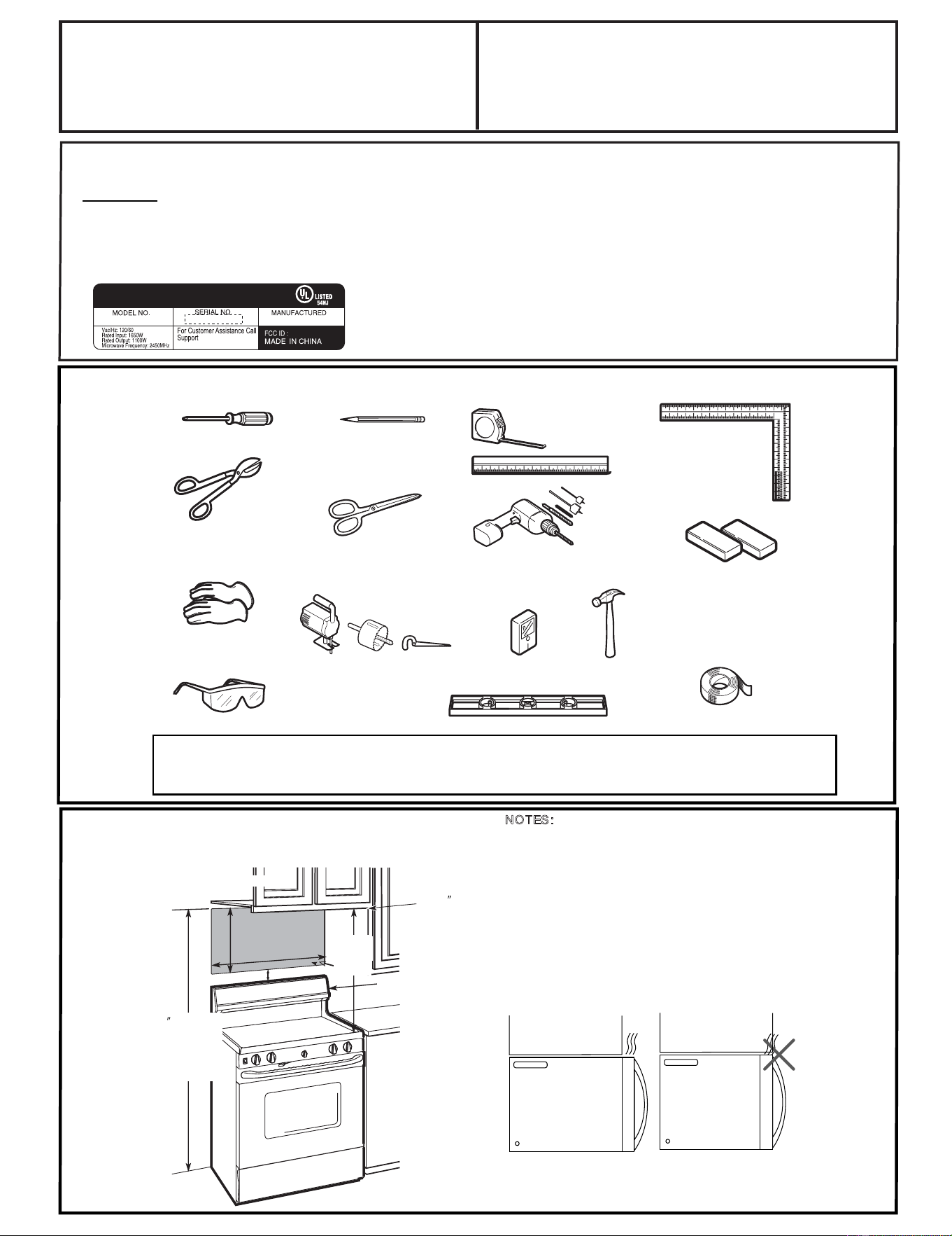
MOUNTING SPACE
NOTES:
•
The between the cabinets must be
30“(76.2 cm)wide and free of obstructions.
•
If you are going to vent your microwave oven
to the outside, see Hood Exhaust Section for
exhaust duct preparation.
• When installing the microwave oven beneath
smooth, flat cabinets, be careful to follow the
instructions on the top cabinet template for
power cord clearance.
BottomEdge of
Cabinet Needs to
be 30
(76.2 cm)
or More fromthe
Cooking Surface
Backsplash
66 (167.6 cm)
or more from
the oor to the
30 (76.2 cm)
2
(5.1 cm)
30
(76.2 cm)
min.
16
1
⁄
2
(41.9 cm)
Cabi netCabi net
NOTE: Maximum cabinet depth is 15
fl
top of the
microwave
acesp
''
''
''
''
''
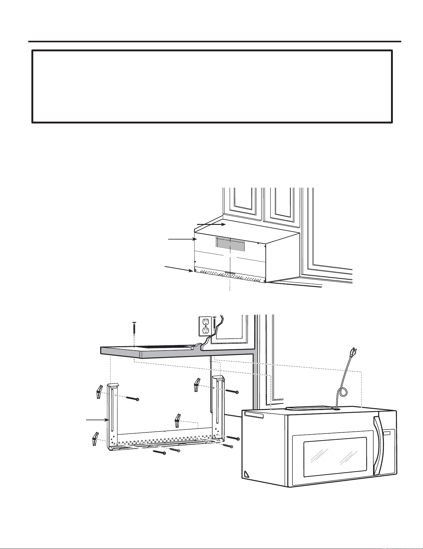
A06823408
NOTE:
For BOK installation – use hardware from over the range microwave unit which has 2
toogle bolts and 2 wood screws for mounting BOK. In addition, there are 2 toggle bolts in the
BOK to complete proper installation.
Bump out kit installs with Over the Range models
in which the serial
number of the unit begins with
To verify proper
unit, check the rating
label
located on the inside of the
doo
r
.
See below example:
KGXXXXXXX.
KGXXXXXXXX
XXXXXXXXXX XXXXXX

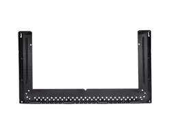
Bump-Out Kit
Bracket
IMPORTANT:
C
3/
8
"
T
O
E
D
G
E
N
O
T
E
:
I
T
I
S
V
ER
Y
I
MPO
R
T
A
N
T
T
O
R
E
A
D
A
N
D
F
OL
LO
W
T
H
E
D
I
RE
C
T
I
O
N
S
I
N
T
HE
I
N
S
TAL
L
A
T
I
O
N
I
N
S
T
RU
C
T
I
O
N
S
B
EF
O
RE
P
R
OC
E
ED
I
N
G
W
I
T
H
T
H
I
S
R
E
AR
W
A
LL
T
EM
P
L
A
T
E
.
T
h
i
s
Re
a
r
W
a
l
l
T
e
m
p
l
a
t
e
se
r
v
e
s
t
o
p
o
s
i
tio
n
t
h
e
b
o
t
t
o
m
mo
u
n
t
i
n
g
p
l
a
t
e
a
n
d
t
o
l
o
c
a
t
e
th
e
h
o
r
iz
o
n
t
a
l
e
xh
a
u
st
o
u
t
l
e
t
.
1
.
U
s
e
a
l
e
v
e
l
t
o
ch
e
c
k
t
h
a
t
t
h
e
t
e
m
p
l
a
t
e
i
s
p
o
s
i
t
i
o
n
e
d
a
c
cu
r
a
t
e
l
y
.
2
.
L
o
c
a
t
e
a
n
d
m
a
r
k
a
t
l
e
a
s
t
o
n
e
s
t
u
d
o
n
th
e
l
ef
t
o
r
r
i
gh
t
s
id
e
o
f
t
h
e
c
e
n
t
e
r
l
i
n
e
.
It i
s
i
m
p
o
rta
n
t
t
o
u
s
e
a
t
l
e
a
s
t
o
n
e
w
o
o
d
scr
e
w
m
o
u
n
t
e
d
f
i
r
mly
i
n
a
s
t
u
d
t
o
s
u
p
p
o
rt
t
h
e
w
e
i
g
h
t
of
t
h
e
m
i
c
r
o
w
a
ve
.
M
a
r
k
t
w
o
a
d
d
i
ti
o
n
a
l
,
e
ve
n
l
y
s
p
a
c
e
d
l
o
c
a
t
i
o
n
s
f
o
r
t
h
e
s
u
pp
l
i
e
d
t
o
g
g
l
e
b
o
l
t
s
.
3
.
D
r
i
l
l
h
o
l
e
s
i
n
t
h
e
m
a
r
k
ed
l
o
ca
t
i
o
n
s
.
W
h
e
r
e
t
h
e
r
e
is
a
s
t
u
d
,
d
r
i
l
l
a
3
/
1
6
" h
o
l
e
f
o
r
w
o
o
d
s
c
r
e
w
s
.
F
o
r
h
o
l
e
s
t
h
a
t
d
o
n
o
t
lin
e
u
p
wi
t
h
a
s
tu
d
,
d
r
i
l
l
5
/
8
"
h
o
l
e
s
fo
r
t
o
g
g
l
e
b
o
l
t
s
.
DO
N
O
T
I
N
ST
A
L
L
T
H
E
M
OU
N
T
I
N
G
P
L
A
T
E
AT
T
H
I
S
T
I
ME.
4
.
Re
m
o
ve
t
h
e
t
e
m
p
la
t
e
fro
m
t
h
e
r
e
a
r
w
a
l
l
.
5
.
R
e
vi
e
w
t
h
e
I
ns
t
a
lla
t
i
o
n
In
s
t
r
u
c
t
i
o
n
b
o
o
k
fo
r
yo
u
r
i
n
sta
lla
t
i
o
n
situ
a
t
i
o
n
.
Lo
c
at
e
a
nd m
ar
k
h
oles
t
o
al
i
gn
w
ith
ho
les
i
n
t
h
e
m
ou
nt
ing
pla
t
e
.
I
M
P
O
R
T
A
N
T:
LOC
AT
E
A
T
LE
A
ST
ON
E
S
T
UD
ON
E
I
T
H
E
R
S
I
DE
OF
T
H
E
C
E
N
TE
R
LI
N
E
.
M
A
R
K
T
H
E
L
OC
A
T
I
O
N
F
OR
2
A
D
D
I
T
I
O
N
A
L
,
E
V
EN
L
Y
S
P
A
C
ED
T
OG
G
L
E
B
OL
T
S
IN
T
H
E
M
OU
N
T
I
N
G
P
L
A
T
E
A
R
E
A.
Lo
ca
t
e
a
nd
m
ar
k
ho
le
s
t
o
alig
n
w
i
t
h
ho
l
es
i
n
t
he
m
o
u
nt
i
ng
pl
a
t
e
.
I
M
PO
R
T
A
NT
:
LO
C
AT
E
AT
LEA
S
T
ON
E
S
T
U
D
O
N
E
I
T
H
ER
SI
D
E
O
F
T
HE
C
E
NT
E
R
LI
N
E
.
M
A
R
K
T
H
E
LO
C
A
T
I
O
N
F
OR
2
A
D
D
I
T
I
O
N
AL
,
E
V
E
N
LY
S
P
A
C
ED
T
OGG
LE
B
O
L
T
S
I
N T
H
E
M
O
U
N
T
I
N
G
P
LAT
E
A
R
E
A
.
T
r
i
m
t
h
e
r
e
a
r
w
al
l
t
e
m
p
l
a
t
e
al
o
n
g
t
h
e
d
o
t
ted
l
i
n
e.
T
r
i
m
t
h
e
r
e
ar
wal
l
t
e
m
p
l
a
t
e
al
o
n
g
t
h
e
d
o
tte
d
l
i
n
e
.
1
2
"
4
"
Da
r
le
v
u
e
l
t
a
a
l
a
ho
j
a
pa
r
a
c
on
s
u
l
t
ar
l
a
v
e
r
s
ió
n
e
n
E
s
p
a
ñ
ol
.
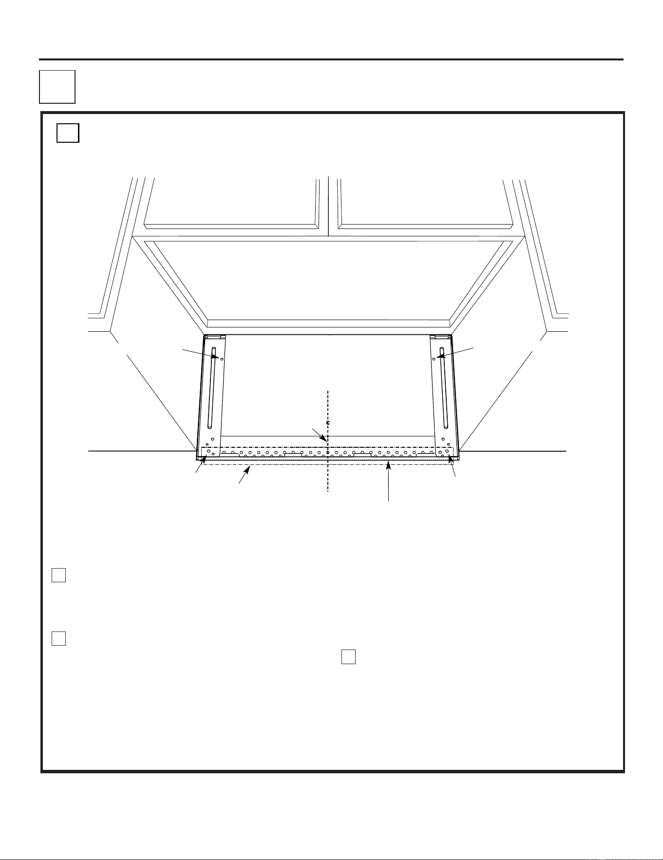
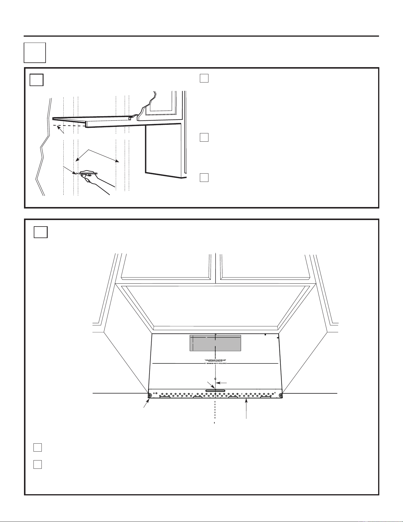
Rear wall template
Installation Instructions
DAMAGE – SHIPMENT/INSTALLATION
• If the unit is damaged in shipment, return the unit to the store in which it was bought for
repair or replacement
• If the unit is damaged by the customer, repair or replacement is the responsibility of the
customer
• If the unit is damaged by the installer (if other than the customer), repair or replacement
must be made by arrangement between customer and installer
•
Move the top cabinet template that comes with your OTR microwave
2. ” forward when installing from bac wall.
•
Use the rear wall template that comes with your OTR microwave to
identify mounting location for the bump out kit.
Move top cabinet template forward 2.2 ”
Mark lowest edge of bracket
Place the Bump Out Kit Bracket in place of rear wall template location making sure that the bottom edge lines up.
5
2
k
5
2

Installation Instructions
Find the studs, using one of the following methods:
A. Stud finder – a magnetic device which locates nails.
OR
B. Use a hammer to tap lightly across the mounting
surface to find a solid sound. This will indicate a stud
location.
After locating the stud(s), find the center by probing
the wall with a small nail to find the edges of the stud.
Then place a mark halfway between the edges. The
center of any adjacent studs should be 16" or 24" from
this mark.
Draw a line down the center of the studs.
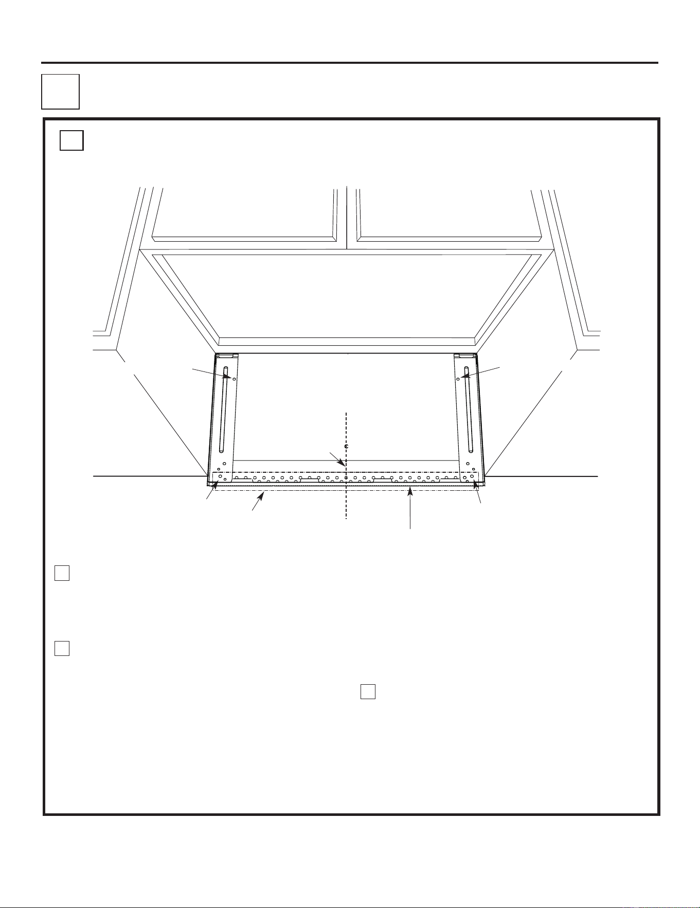
THE BUMP-OUT BRACKET MUST BE ED
AT
LEAST ONE
WALL STUD.
1
FINDING THE WALL STUDS
A.
2
PLACEMENT OF THE BUMP-OUT BRACKET
1
Wall Studs
Level line for front overhang
Center
3
B.
Centerline
notches
Draw a Vertical Line
on Wall from Center
of Top Cabinet
Draw a horizontal line on wall at the
bottom of “Rear Wall Template”.
Horizontal Line
C
L
3/8" TO EDGE
%#76+10Ä+(':*#756#ਸ਼+5
215+6+10'&
1765+&'
4'%1//'0&'&&+/'05+
10)4'#5'Ä.#&'0#+49+..
&+5%*#4)'+061*175'5647%674'
/+0+/7/9+&6*4'37+4'&
4'#49#..6'/2.#6'
NOTE: IT IS VERY IMPORTANT TO
READ AND FOLLOW THE DI
RECTIONS
IN THE INSTALLATION INSTRUCTIONS
BEFORE PROCEEDI
NG WITH
THIS
REAR WALL TEMPLATE.
This Rear Wal
l Template serves t
o position the bottom
mounting plate and to locate
the horizontal exhaust
outlet.
1. Use a level to check th
at the template is positioned
accurately.
2. Locate and ma
rk at least one stud on the left or
right side of the centerlin
e.
016'
It is important to use at least one wood
screw mounted firmly in a stud to s
upport the weight
of the microwave. Mark two add
itional, evenly spaced
locations for the supp
lied toggle bolts.
3. Drill holes in the marked locatio
ns. Where there is
a stud, drill a 3/16" hole for
wood screws. For hole
s
that do not line up with a st
ud, drill 5/8" holes for
toggle bolts.
016'
DO NOT INSTALL THE M
OUNTING PLATE
AT THIS TIME.
4. Remove the tem
plate from the rear wall.
5. Review the Installation Instru
ction book for your
installation situation.
Locate and mark
holes to align with h
oles in the
mounting plat
e.
IMPORTANT:
LOCATE
AT LEAST ONE
STUD ON EITHER SIDE OF
THE CENTERLINE.
MARK THE LOCATION FOR 2
ADDITIONAL, EVENLY
SPACED
TOGGLE BOLTS IN
THE MOUNTING PLATE
AREA.
Locate and mark
holes to align with hol
es in the
mounting plat
e.
IMPORTANT:
LOCATE
AT LEAST ONE
STUD ON EITHER SIDE OF
THE CENTERLINE.
MARK THE LOCATION FOR 2
ADDITIONAL, EVENLY
SPACED
TOGGLE BOLTS IN
THE MOUNTING PLATE
AREA.
Trim the rear
wall template al
ong the dotted
line.
%
#
$
%
&
(%76176(14*14+<106#.
1765+&'':*#756
%76*1.'6*417)*
4'#49#..
(14':*#756#ਸ਼
12"
4"
Darle vuelta a la hoja para consultar la
versión en Español.
Draw a vertical line on the wall at the center of the
30" wide space.
1
2
Draw a horizontal line on the wall at the bottom of
“Rear Wall Template”.
MARK THE LOWEST EDGE OF BRACKET
INSTALL IN
3
Installation Instructions
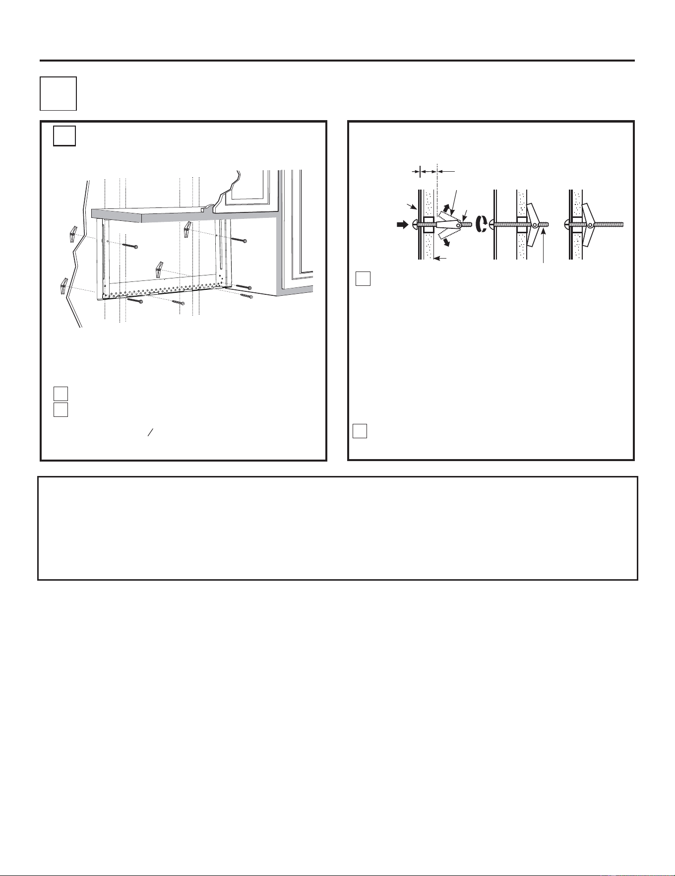
PLACEMENT OF THE BUMP-OUT BRACKET
1
.
ALIGNING THE WALL PLATE
Place mounting plate on the wall, making sure that the
bottom of mounting plate is touching the horizontal line
drawn with rear template. Line up the notch and center
line on the mounting plate to the center line on the wall.
While holding mounting plate with one hand, draw circles
on the wall at holes A, B, C and D (see illustration above).
Four holes must be used for mounting.
NOTE: Holes C and D are inside area E. If neither C nor D
is in a stud, find a stud somewhere in area E and draw
a fifth circle to line up with the stud. It is important to
use at least one wood screw mounted firmly in a stud to
support the weight of the oven.
Set the mounting plate aside.
Drill holes on the circles. If there is a stud, drill a
3
ø
16
” hole
for wood screws. For holes that don’t line up with a stud,
drill a
5
ø
8
” hole for toggle bolts.
NOTE: DO NOT MOUNT THE PLATE AT THIS TIME.
Hole Location A
Hole Location B
Area E
Hole Location C
Hole Location D
1
2
3
C
Centerline
Area E
4
Installation Instructions
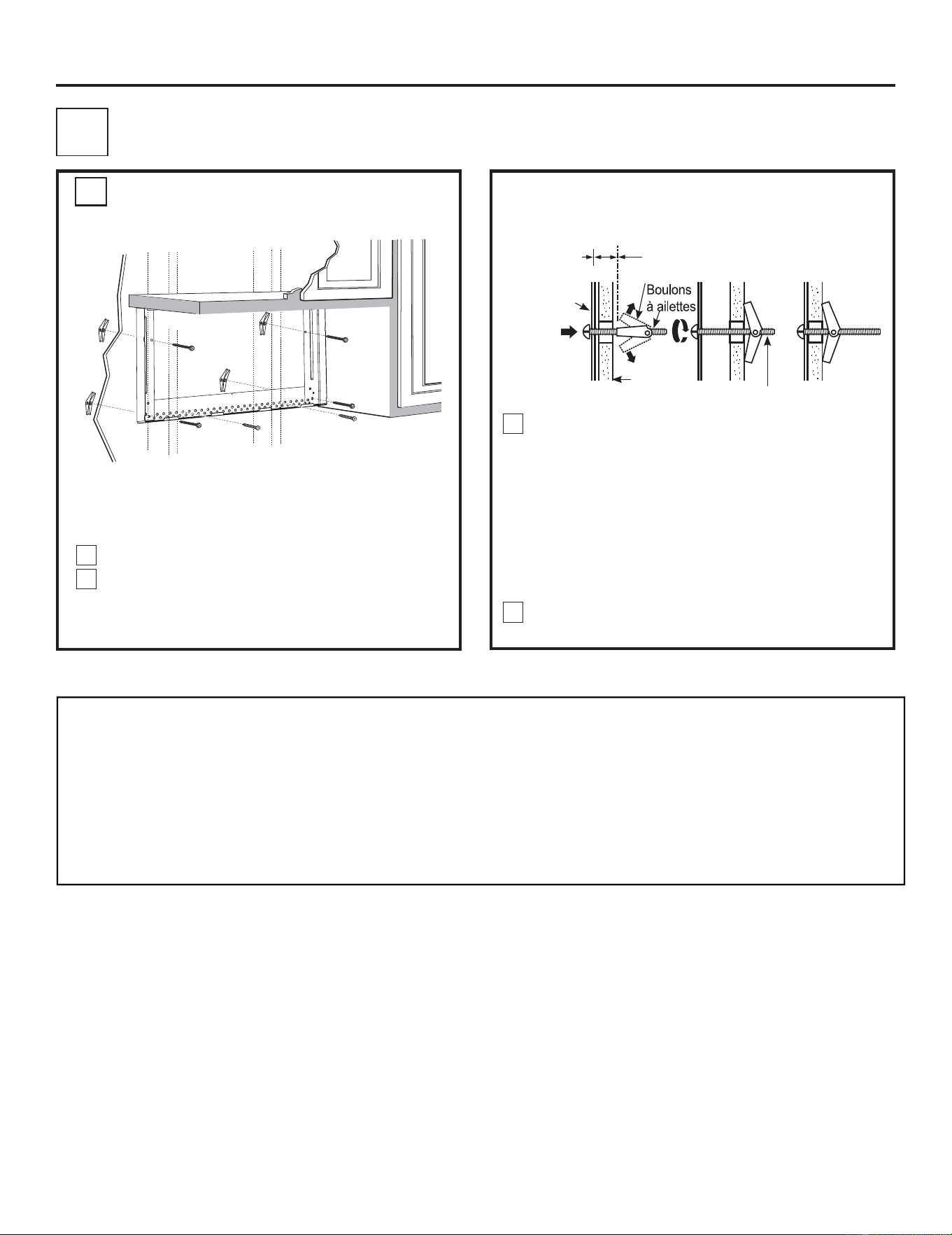
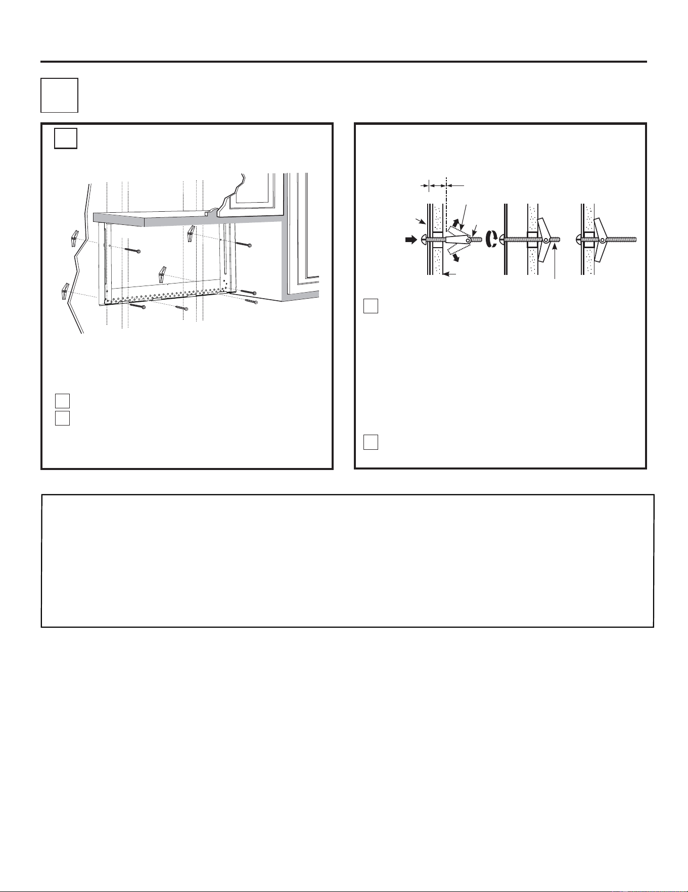
Attach the plate to the wall using toggle bolts.
At least one wood screw must be used to attach the
plate to a wall stud. NOTE: Use from OTR
packaging and bump out kit packaging .
Remove the toggle wings from the bolts.
Insert the bolts into the mounting plate through the
holes go into drywall and reattach the
toggle wings to
3
4
” onto each bolt.
1
2
INSTALLING THE BUMP-OUT BRACKET
2
ATTACH THE MOUNTING
A.
Place the mounting plate against the wall and insert
the toggle wings into the holes in the wall to mount
the plate.
CAUTION: careful to avoid pinching fingers between
the back of the mounting plate and the wall.
Tighten all bolts. Pull plate away from the wall to
help tighten the bolts.
3
4
Wall
Mounting
Plate
Spacing for
Toggles M ore Than
Wall Thickness
Bolt End
Toggle
Bolt
Toggle Wings
To use toggle bolts:
hardware
designated to
Be
the
PLATE TO THE WALL
NOTE:There are two things to be noted before tig-
htening toggle bolts and wood screw. First, make
sure the tabs on the mounting plate touch the bot
tom
of
the
cabinet
when
puched
flush
against
the
wall. Second, make sure the plate is properly
under
the
cabinet.
centered
-
5
4
NOTE :
1、Refer to the over the range installation instructions to finish installation of unit.
2、When BOK is mounted to larger cavity OTR models( like 1.8 / 2.1 models),
the sides of BOK will not go all the way to top, and the gap is about 0.91'' to
the cabinet.
OUTILS QUE VOUS AVEZ BESOIN
# 1 Tournevis cruciforme
Crayon
Règle ou ruban à mesurer
et droitstraigedge
Carré de menuisier
(facultatif)
Cisailles (pour découper
Shock absorber, if
reuirednécessaire)
perceuse électrique avec
, , et drill bits
3
⁄
16“
1
⁄2“
5
⁄8“
Gants
Scie(sabre, trou ou trou de serrure) Un detecteur de colombage ou
un martrau Hammer (optional)
Niveau
Ruban adhésif et cache-adhesif
Les ciseaux
(Pour découper le
modèle, si nécessaire)
Lunettes de protection
ESPACE DE MONTAGE
REMARQUES:
Backsplash
30 (76.2 cm)
2
(5.1 cm)
30
(76.2 cm)
min.
16
1
⁄
2
(41.9 cm)
Cabi netCabinet
REMARQUE: La profondeur maximale
de l'armoire est de 15 "
''
''
''
''
Installation Le KitBump-Out
Instructions
Pour les armoires profondes
de 15 pouces
AVANT QUE TU COMMENCES
Lisez ces instructions complètement et soigneusement.
IMPORTANT:
A06823408
•
• Enregistrez ces instructions pour l'utilisation de
l'inspecteur local.
• Respectez tous les codes et ordonnances applicables.
• Note au client: conservez ces instructions pour référence
ultérieure.
• Niveau de compétence - L'installation de cet appareil nécessite
des compétences mécaniques et électriques de base.
• Une installation appropriée est la responsabilité d’installateurs.
• La défaillance du produit résultant d'une mauvaise installation
n'est pas couverte par la garantie.
Note à l'installateur - Assurez-vous de laisser ces instructions
avec le consommateur.
Blocs de remplissage ou
morceaux de bois en ferraille, si
nécessaire pour l'espacement
des armoires supérieures (used
on recessed bottom
cabinet installations only)
• L'espace entre les armoires doit être de 30 po
(76,2 cm) de largeur et sans obstruction.
• Si vous prévient l'évacuation de votre four à
micro-ondes à l'extérieur, voir la section d'échappe-
ment des capuchons pour la préparation des
conduits d'échappement.
• Lors de l'installation du four à micro-ondes sous des
armoires lisses, faites attention de respecter les
instructions sur le modèle de l'armoire supérieure
pour le jeu de cordon d'alimentation.
Le bord
inférieur de
l'armoire doit
être de 30 (76,2
cm) ou plus de
la surface de
cuisson
66 (167,6 cm)
ou plus du
haut au
micro-ondes
Remarque : Pour installer BOK, utilisez le matériel du four microonde à hotte intégrée équipé
de deux boulons à ailettes et de deux vis à bois Pour finir, utilisez les deux boulons à ailettes
contenues dans BOK pour parachever l’installation.
L'installation du kit de pompage avec les modèles de la gamme
Dans lequel le numéro de série de l'unité commence par
KGXXXXXXX. Pour vérifier l'unité appropriée, vérifiez l'étiquette
de notation située à l'intérieur de la porte.
Voir ci-dessous exemple :
KGXXXXXXXX
XXXXXXXXXX XXXXXX

KitBump-Out
Support
IMPORTANT:
C
3/
8
"
T
O
E
D
G
E
N
O
T
E
:
I
T
I
S
V
ER
Y
I
MPO
R
T
A
N
T
T
O
R
E
A
D
A
N
D
F
OL
LO
W
T
H
E
D
I
RE
C
T
IO
N
S
I
N
T
HE
I
N
S
TAL
L
A
T
I
O
N
I
N
S
T
RU
C
T
I
O
N
S
B
EF
O
RE
P
R
OC
E
ED
I
N
G
W
I
T
H
T
H
I
S
R
E
AR
W
A
LL
T
EM
P
L
A
T
E
.
T
h
i
s
Re
a
r
W
a
l
l
T
e
m
p
l
a
t
e
se
r
v
e
s
t
o
p
o
s
i
tio
n
t
h
e
b
o
t
t
o
m
mo
u
n
t
i
n
g
p
l
a
t
e
a
nd
t
o
l
o
c
a
t
e
th
e
h
o
r
iz
o
n
t
a
l
e
xh
a
u
st
o
u
t
l
e
t
.
1
.
U
s
e
a
l
e
v
e
l
t
o
ch
e
c
k
t
h
a
t
t
h
e
t
e
m
p
l
a
t
e
i
s
p
o
s
i
t
i
o
n
e
d
a
c
cu
r
a
t
e
l
y
.
2
.
L
o
c
a
t
e
a
n
d
m
a
r
k
a
t
l
e
a
s
t
o
n
e
s
t
u
d
o
n
th
e
l
ef
t
o
r
r
i
gh
t
s
id
e
o
f
t
h
e
c
e
n
t
e
r
l
i
n
e
.
I
t
i
s
i
m
p
o
rta
n
t
t
o
u
s
e
a
t
l
e
a
s
t
o
n
e
w
o
o
d
scr
e
w
m
o
u
n
t
e
d
f
i
r
ml
y
i
n
a
s
t
u
d
t
o
s
u
p
p
o
rt
t
he
w
e
i
g
h
t
of
t
h
e
m
i
c
r
o
w
a
ve
.
M
a
r
k
t
w
o
a
d
d
i
ti
o
n
a
l
,
e
ve
n
l
y
s
p
a
c
e
d
l
o
ca
t
i
o
n
s
f
o
r
t
h
e
s
u
pp
l
i
e
d
t
o
g
g
l
e
b
o
l
t
s
.
3
.
D
r
i
l
l
h
o
l
e
s
i
n
t
h
e
m
a
r
k
ed
l
o
ca
t
i
o
n
s
.
W
h
e
re
t
h
e
r
e
is
a
s
t
u
d
,
d
r
i
l
l
a
3
/
1
6
" h
o
l
e
f
o
r
w
o
o
d
s
c
r
e
w
s
.
F
o
r
h
o
l
e
s
t
h
a
t
d
o
n
o
t
l
i
n
e
u
p
wi
t
h
a
s
tu
d
,
d
r
i
l
l
5
/
8
"
h
o
l
e
s
fo
r
t
o
g
g
l
e
b
o
l
t
s.
DO
N
O
T
I
N
ST
A
L
L
T
H
E
M
OU
N
T
I
N
G
P
L
A
T
E
AT
T
H
I
S
T
I
ME.
4
.
Re
m
o
ve
t
h
e
t
e
m
p
la
t
e
fro
m
t
h
e
r
e
a
r
w
a
l
l
.
5
.
R
e
vi
e
w
t
h
e
I
ns
t
a
l
l
a
t
i
o
n
In
s
t
r
u
c
t
i
o
n
b
o
o
k
fo
r
yo
u
r
i
n
sta
l
l
a
t
i
o
n
situ
a
t
i
o
n
.
Lo
c
at
e
a
nd m
ar
k
h
oles
t
o
al
i
gn
w
ith
ho
les
i
n
t
h
e
m
ou
nt
ing
pl
a
t
e
.
I
M
P
O
R
T
A
N
T:
LOC
AT
E
A
T
LE
A
ST
ON
E
S
T
UD ON
E
I
T
H
E
R
S
I
DE
OF
T
H
E
C
E
N
TE
R
LI
N
E
.
M
A
R
K
T
H
E
L
OC
A
T
I
O
N
F
OR
2
A
D
D
I
T
I
O
N
A
L
,
E
V
EN
L
Y
S
P
A
C
ED
T
OG
G
L
E
B
OL
T
S
IN
T
H
E
M
OU
N
T
I
N
G
PL
A
T
E
A
R
E
A.
Lo
ca
t
e
a
nd
m
ar
k
ho
le
s
t
o
alig
n
w
i
th
ho
l
es
i
n
t
he
m
o
u
nt
i
ng
pl
a
t
e
.
I
M
PO
R
T
A
NT
:
LO
C
AT
E
AT
LEA
S
T
ON
E
S
T
U
D
O
N
E
I
T
H
ER
SI
D
E
O
F
T
HE
C
E
NT
E
R
LI
N
E
.
M
A
R
K
T
H
E
LO
C
A
T
I
O
N
F
OR
2
A
D
D
I
T
I
O
N
AL
,
E
V
E
N
LY
SP
A
C
ED
T
OGG
LE
B
O
L
T
S
I
N T
H
E
M
O
U
NT
I
N
G
P
LA
T
E
A
R
E
A
.
T
r
i
m
t
h
e
r
e
a
r
w
al
l
t
e
m
p
l
a
t
e
al
o
n
g
t
h
e
d
o
t
t
ed
l
i
n
e.
T
r
i
m
t
h
e
r
e
ar
wal
l
t
e
m
p
l
a
t
e
al
o
n
g
t
h
e
d
o
tte
d
l
i
n
e
.
1
2
"
4
"
Da
r
le
v
u
e
l
t
a
a
l
a
ho
j
a
pa
r
a
c
on
s
u
l
t
a
r
l
a
v
e
r
s
ió
n
e
n
E
s
p
a
ñ
o
l
.
Modèle de paroi arrière
Instructions d'installation
DOMMAGES - EXPÉDITION / INSTALLATION
Déplacer le modèle supérieur de
l'armoire vers l'avant 2.2 "
Marquez le bord inférieur du support
Placez le support du kit anti-retour à la place de l'emplacement du modèle de la paroi arrière, en vous
assurant que le bord inférieur s'allonge.
• Si l'appareil est endommagé lors de l'expédition, renvoyer l'unité au magasin dans lequel
il a été acheté pour réparation ou remplacement
• Si l'appareil est endommagé par le client, la réparation ou le remplacement est la respon-
sabilité du client
• Si l'appareil est endommagé par l'installateur (si autre que le client), la réparation ou le
remplacement doit être effectué par accord entre le client et l'installateur
• Déplacez le modèle d'armoire supérieur fourni avec votre microonde OTR 2.2
• Utilisez le modèle de la paroi arrière livré avec votre micro-ondes OTR pour
identifier l'emplacement du kit de bump out.
5
5
7
à
partir du mur arrière.
Instructions d'installation
Trouvez les poteaux, using one of the following methods:
A. Un détecteur de colombages – un dispositif
magnétique qui localise les ongles.
OU
B. Utilisez un marteau pour tirer légèrement sur la
surface de montage pour trouver un son solide.
Cela indiquera un emplacement de poteaux.
Après avoir localisé les poteaux, trouvez le centre en
sondant le mur avec un petit ongle pour trouver les bords
du poteaux. Ensuite, placez une marque à mi-chemin
entre les bords. Le centre de tous les poteaux adjacents
devrait être de 16 "ou 24" de cette marque.
Dessinez une ligne au centre des poteaux.
LE FOUR DOIT ETRE
UN POTEAU.
1
TROUVER LES POTEAUX MURAX
A.
2
PLACEMENT DU SUPPORT DE BUMP-OUT
1
Des poteauxmuraux
Ligne de niveau pour porte-à-faux avant
Centre
3
B.
Les coches
de ligne
mediane
MODELE DE PAROI ARRIÈRE
Dessiner une ligne
verticale sur le paroi du
centreof Top Cabinet
Dessinez une ligne horizontale sur le paroi au
bas de "Modèle de paroi « « arriere’ arrière".
Ligne horizontale
C
L
3/8" TO EDGE
Localisez et marquez les trous pour aligner avec les trous dans
la plaque de montage.
IMPORTANT:
LOCALISERAU MOINS UNPOTEAUSUR TOUT CÔTÉ DE
LIGNE MEDIANE.
MARQUEZ DE L’EMPLACEMENT POUR DEUX BOULONS D’AILETTES
RÉGULIÈREMENT ESPACÉS SUR LA PLAQUE DE MONTAGE.
Localisez et marquez les trous pour aligner avec les trous dans la
plaque de montage.
IMPORTANT:
LOCALISERAU MOINS UNPOTEAU SUR TOUT COTEDE LA
LIGNE MEDIANE.
MARQUEZ DE L’EMPLACEMENT POUR DEUX BOULONS D’AILETTES
RÉGULIÈREMENT ESPACÉS SUR LA PLAQUE DE MONTAGE
Trim the rear wall template along the dotted line.
12"
4"
Dessinez une ligne verticale sur le paroi au centre
de l'espace large de 30 ".
1
2
Dessinez une ligne horizontale sur le paroi au bas de
"Modèle de paroi arrière".
MARQUEZ LE PLUS BAS BORD DE SUPPORT
F. COUPER POUR L'ECHAPPEMENT
HORIZONTAL EXTERIEUR
COUPER LE TROU PAR REAFWALL POUR ADAPTATEUR D'ECHAPPEMENT
REMARQUE: IL EST TRÈS MPORTANT DE
LIRE ET DE SUIVRE LES INSTRUCTIONS
DANS LES INSTRUCTIONS D'INSTALLATION
AVANT DE PROCEDER AVEC CE MODÈLE DE
PAROI ARRIÈRE.
Ce modèle de mur arrière sert à positionner la plaque de montage
inférieure et à localiser la sortie de l'échappement horizontal.
1. Utilisez un niveau pour vérifier que le modèle est positionné avec
précision.
2. Localisez et marquez au moins un poteau sur le côté gauche ou
droit de la ligne médiane.
REMARQUE: Il est important d'utiliser au moins une vis à bois montée
fermement dans un poteaux pour supporter le poids du
micro-ondes. Marquez deux emplacements supplémentaires et
espacés pour les boulons à ailettes fournis.
3. Percez les trous dans les emplacements marqués. Là où il y a un
poteau, percer un trou de 3/16 "pour les vis à bois. Pour les trous
qui ne s'alignent pas avec un goujon, percez des trous de 5/8"
pour les boulons à ailettes.
REMARQUE: NE PAS INSTALLER LA PLAQUE DE MONTAGE EN
CE MOMENT.
4.Retirez le modèle de la paroi arrière.
5. Passez en revue le carnet d'instructions d'installation pour votre
Situation d'installation.
Darle vuelta a la hoja para consultar la
versión en Español.
8
INSTALLÉ DANS
Instructions d’installation
PLACEMENT DU SUPPORT DE BUMP-OUT
1
.
ALIGNEMENT DE LA PLAQUE MURALE
Emplacement du trou A
Emplacement du trou B
Zone E
Emplacement du trou C
Emplacement du trou D
1
2
3
C
Ligne mediane
Zone E
Placez la plaque de montage sur le paroi, en vous
assurant que le fond de la plaque de montage touche
la ligne horizontale dessinée avec le modèle arrière.
Alignez lacoche et la ligne centrale sur la plaque de
montage sur la ligne médiane sur le mur.
REMARQUE: Les trous C et D sont à l'intérieur de la
zone E. Si ni C ni D ne se trouvent dans un poteau,
trouvez un poteau quelque part dans la zone E et
dessinez un cinquième cercle pour aligner le poteau.
Il est important d'utiliser au moins une vis à bois
montée fermement dans un poteau pour supporter le
poids du four.
Mettre la plaque de montage de côté
Percez les trous sur les cercles. S'il y a un poteau,
percer un trou de
3
/
16
" po pour les vis à bois. Pour les
trous qui ne s'alignent pas avec un poteau,
Percer un trou de
5
/
8
" pour les boulons à ailettes.
REMARQUE: NE MONTEZ PAS LA PLAQUE À
CETEMPS
Tout en tenant la plaque de montage d'une main,
dessinez des cercles sur le paroi aux trous A, B, C et
D (voir illustration ci-dessus). Il faut utiliser quatre
trous pour le montage.
9
Instructions d’installation
Insérez les boulons dans la plaque de montage
à travers les trous désignés pour aller dans la
cloison sèche et reliez les ailettes à
3
/
4
"sur
chaque boulon.
1
2
INSTALLATION DU SUPPORT DE BUMP-OUT
2
ATTACHEZ LA PLAQUE DE
MONTAGE AU PAROI
A.
Placez la plaque de montage contre le paroi et
insérez les ailettes dans les trous du paroi pour
monter la plaque.
Serrer tous les boulons. Tirez le loin du mur pour
aider à resserrer les boulons.
3
4
Paroi
Plaque de
montage
Espacement pour
les ailettes plus que
epaisseur du paroi
Extrémités des boulons
Ailes de basculement
Pour utiliser des boulons à ailettes:
ATTENTION: veillez à éviter de pincer les doigts entre
le dos de la plaque de montage et le paroi.
REMARQUE: Avant de serrer les boulons à ailettes
et la vis à bois, assurez-vous que les onglets de la
plaque de montage sont en contact avec le bas de
l'armoire lorsque vous êtes enfoncées contre le mur
et que la plaque est bien centrée sous l'armoire.
Fixez la plaque sur le paroi à l'aide de boulons à ailettes
(2-4). Au moins une vis à bois doit être utilisée pour
attacher la plaque à un montant mural. REMARQUE:
Utilisez du matériel à partir d'un emballage
OTR
Retirer les ailettes de basculement.
10
et le kit
de support de fixation.
REMARQUE :
Voir le guide d’installation de la hotte intégrée pour
achever
l’installation du
produit.
1、
2、
Lorsque BOK est monté sur des modèles OTR à cavité plus larg
e
(comme les
modèles
1.8 / 2.1). Les côtés du BOK n'iront pas tou
t en haut, et l'espace est
d'environ 0.91" jusqu'au cabinet(/armoire)
.
HERRAMIENTAS NECESARIAS
Destornillador Phillips #1
Lápiz
Regla o cinta métrica
Escuadra de
carpintero
(opcional)
Tijeras de hojalatero
(para cortar piezas
metálicas, si es necesario)
Taladro eléctrico con brocas de
, , y .
3
⁄
16“
1
⁄2“
5
⁄8“
Guantes
Sierra (de vaivén,
perforadora o de punta)
Detector de vigas o martillo
(opcional)
Nivel
Cinta adhesiva
Tijeras (para cortar
plantillas, si es necesario)
Gafas de protección
ESPACIO DE MONTAJE
OBSERVACIONES:
Protector de
salpicaduras
30 (76.2 cm)
2
(5.1 cm)
30
(76.2 cm)
mínimo.
16
1
⁄
2 (41.9 cm)
Gabinete Gabinete
OBSERVACI N: La profundidad
máxima del gabinete es
de 15".
''
''
''
''
Instrucciones
de instalación
Kit para microondas
sobre la estufa
Para gabinetes de 15" de
profundidad
ANTES DE COMENZAR
Lea estas instrucciones atentamente y por completo.
IMPORTANTE:
A06823408
•
• Guarde estas instrucciones para uso por el inspector
local.
• Se debe cumplir con todos los códigos y ordenanzas
locales.
• Nota al consumidor: Guarde estas instrucciones para futura
referencia.
• Nivel de habilidad: La instalación de este aparato requiere de
habilidades básicas en electricidad y mecánica.
• La instalación adecuada es responsabilidad de la persona que
realice la instalación.
• Los fallos en el productos causados por una instalación
incorrecta no serán cubiertos por la garantía.
Nota al instalador: Asegúrese de dejar estas instrucciones al
usuario.
Bloques de relleno o piezas
sobrantes de madera, de ser
necesarias para el espaciamien-
to del gabinete superior
(utilizados sólo para instalacio-
nes de gabinetes empotrados)
• El espacio hasta el gabinete debe ser de al menos
30" (76,2 cm) de ancho y estar libre de obstruccio-
nes.
• Si va a ventilar el horno microondas hacia afuera,
vea la sección sobre la Campana extractora para
leer sobre la preparación del conducto de extracción.
• Al instalar el horno microondas debajo de gabinetes
lisos y planos, asegúrese de seguir las instrucciones
de cable de alimentación en la plantilla del gabinete
superior.
La parte inferior
del gabinete
debe estar al
menos 30" (76,2
cm) o más
alejado de la
superficie de
cocción.
66 (167,6 cm)
o más, desde
la superficie
superior hasta
el microondas
NOTA: Para instalación BOK - use hardware de la unidad de microondas que tiene 2 pernos
de palanca y 2 tornillos de madera para montar BOK. Además, hay 2 pernos de palanca en el
BOK para completar la instalación.
Instalación para modelos sobre la estufa en los que el número de
serial comienza con KGXXXXXXX. Para verificar que sea la unidad
correcta, por favor vea la etiqueta del lado interno de la puerta,
como se muestra en el ejemplo a continuación:
KGXXXXXXXX
XXXXXXXXXX XXXXXX
Kit de colocación
Soporte
IMPORTANTE:
C
3/
8
"
T
O
E
D
G
E
N
O
T
E
:
I
T
I
S
V
ER
Y
I
MPO
R
T
A
N
T
T
O
R
E
A
D
A
N
D
F
OL
LO
W
T
H
E
D
I
RE
C
T
IO
N
S
I
N
T
HE
I
N
S
TAL
L
A
T
I
O
N
I
N
S
T
RU
C
T
I
O
N
S
B
EF
O
RE
P
R
OC
E
ED
I
N
G
W
I
T
H
T
H
I
S
R
E
AR
W
A
LL
T
EM
P
L
A
T
E
.
T
h
i
s
Re
a
r
W
a
l
l
T
e
m
p
l
a
t
e
se
r
v
e
s
t
o
p
o
s
i
tio
n
t
h
e
b
o
t
t
o
m
mo
u
n
t
i
n
g
p
l
a
t
e
a
nd
t
o
l
o
c
a
t
e
th
e
h
o
r
iz
o
n
t
a
l
e
xh
a
u
st
o
u
t
l
e
t
.
1
.
U
s
e
a
l
e
v
e
l
t
o
ch
e
c
k
t
h
a
t
t
h
e
t
e
m
p
l
a
t
e
i
s
p
o
s
i
t
i
o
n
e
d
a
c
cu
r
a
t
e
l
y
.
2
.
L
o
c
a
t
e
a
n
d
m
a
r
k
a
t
l
e
a
s
t
o
n
e
s
t
u
d
o
n
th
e
l
ef
t
o
r
r
i
gh
t
s
id
e
o
f
t
h
e
c
e
n
t
e
r
l
i
n
e
.
I
t
i
s
i
m
p
o
rta
n
t
t
o
u
s
e
a
t
l
e
a
s
t
o
n
e
w
o
o
d
scr
e
w
m
o
u
n
t
e
d
f
i
r
ml
y
i
n
a
s
t
u
d
t
o
s
u
p
p
o
rt
t
he
w
e
i
g
h
t
of
t
h
e
m
i
c
r
o
w
a
ve
.
M
a
r
k
t
w
o
a
d
d
i
ti
o
n
a
l
,
e
ve
n
l
y
s
p
a
c
e
d
l
o
ca
t
i
o
n
s
f
o
r
t
h
e
s
u
pp
l
i
e
d
t
o
g
g
l
e
b
o
l
t
s
.
3
.
D
r
i
l
l
h
o
l
e
s
i
n
t
h
e
m
a
r
k
ed
l
o
ca
t
i
o
n
s
.
W
h
e
re
t
h
e
r
e
is
a
s
t
u
d
,
d
r
i
l
l
a
3
/
1
6
" h
o
l
e
f
o
r
w
o
o
d
s
c
r
e
w
s
.
F
o
r
h
o
l
e
s
t
h
a
t
d
o
n
o
t
l
i
n
e
u
p
wi
t
h
a
s
tu
d
,
d
r
i
l
l
5
/
8
"
h
o
l
e
s
fo
r
t
o
g
g
l
e
b
o
l
t
s.
DO
N
O
T
I
N
ST
A
L
L
T
H
E
M
OU
N
T
I
N
G
P
L
A
T
E
AT
T
H
I
S
T
I
ME.
4
.
Re
m
o
ve
t
h
e
t
e
m
p
la
t
e
fro
m
t
h
e
r
e
a
r
w
a
l
l
.
5
.
R
e
vi
e
w
t
h
e
I
ns
t
a
l
l
a
t
i
o
n
In
s
t
r
u
c
t
i
o
n
b
o
o
k
fo
r
yo
u
r
i
n
sta
l
l
a
t
i
o
n
situ
a
t
i
o
n
.
Lo
c
at
e
a
nd m
ar
k
h
oles
t
o
al
i
gn
w
ith
ho
les
i
n
t
h
e
m
ou
nt
ing
pl
a
t
e
.
I
M
P
O
R
T
A
N
T:
LOC
AT
E
A
T
LE
A
ST
ON
E
S
T
UD ON
E
I
T
H
E
R
S
I
DE
OF
T
H
E
C
E
N
TE
R
LI
N
E
.
M
A
R
K
T
H
E
L
OC
A
T
I
O
N
F
OR
2
A
D
D
I
T
I
O
N
A
L
,
E
V
EN
L
Y
S
P
A
C
ED
T
OG
G
L
E
B
OL
T
S
IN
T
H
E
M
OU
N
T
I
N
G
PL
A
T
E
A
R
E
A.
Lo
ca
t
e
a
nd
m
ar
k
ho
le
s
t
o
alig
n
w
i
th
ho
l
es
i
n
t
he
m
o
u
nt
i
ng
pl
a
t
e
.
I
M
PO
R
T
A
NT
:
LO
C
AT
E
AT
LEA
S
T
ON
E
S
T
U
D
O
N
E
I
T
H
ER
SI
D
E
O
F
T
HE
C
E
NT
E
R
LI
N
E
.
M
A
R
K
T
H
E
LO
C
A
T
I
O
N
F
OR
2
A
D
D
I
T
I
O
N
AL
,
E
V
E
N
LY
SP
A
C
ED
T
OGG
LE
B
O
L
T
S
I
N T
H
E
M
O
U
NT
I
N
G
P
LA
T
E
A
R
E
A
.
T
r
i
m
t
h
e
r
e
a
r
w
al
l
t
e
m
p
l
a
t
e
al
o
n
g
t
h
e
d
o
t
t
ed
l
i
n
e.
T
r
i
m
t
h
e
r
e
ar
wal
l
t
e
m
p
l
a
t
e
al
o
n
g
t
h
e
d
o
tte
d
l
i
n
e
.
1
2
"
4
"
Da
r
le
v
u
e
l
t
a
a
l
a
ho
j
a
pa
r
a
c
on
s
u
l
t
a
r
l
a
v
e
r
s
ió
n
e
n
E
s
p
a
ñ
o
l
.
Plantilla de la pared posterior
Instrucciones de instalación
DAÑOS - ENVÍO/INSTALACIÓN
Mover el gabinete superior hacia
adelante 2,2 ".
Marcar el borde inferior del soporte
Colocar el soporte del kit en lugar con la plantilla de la pared posterior, asegurándose de que los bordes
inferiores estén alineados.
• Si la unidad se daña durante el envío, puede devolverla a la tienda en la que fue adquirida
para reparación o reemplazo.
• Si la unidad sufre daños causados por el usuario, la reparación o reemplazo será
responsabilidad de éste.
• Si la unidad sufre daños causados por el instalador (si no es el usuario), la reparación o
reemplazo deberá hacerse por acuerdo entre el usuario e instalador.
• Durante la instalación, mueva la plantilla de gabinete superior que viene con su
microondas OTR de 2,2 "
• Utilice la plantilla de la pared posterior que viene con su microondas OTR para
identificar la ubicación para el kit.
5
5
12
de la pared trasera.

Instrucciones de instalación
Encuentre las vigas utilizando uno de los siguientes métodos:
A. Con un detector de vigas - un dispositivo magnético
para ubicar clavos.
O
B. Con un martillo, martillando suavemente sobre la
superficie de montaje hasta dar con un sonido sólido.
Este sonido indica que allí hay un clavo.
Luego de ubicar los clavos, encuentre el centro palpando
la pared con un clavo pequeño para encontrar los bordes
de la viga. Luego coloque una marca a medio camino
entre los bordes. El centro de cualquier viga adyacente
deberá estar a 16" o 24" desde esta marca.
Dibuje una línea por debajo del centro de las vigas.
EL MICROONDAS DEBERÁ ESTAR
AL MENOS UNA VIGA.
1
ENCONTRAR LAS VIGAS DE LA PARED
A.
2
COLOCACIÓN DEL SOPORTE
1
Vigas de pared
Línea de nivel para la parte colgante frontal
Centro
3
B.
Ranuras de
la línea de
centro
Plantilla de pared posterior
Dibuje una línea vertical
en la pared desde el centro
del gabinete superior
Dibuje una línea horizontal en la pared
en la parte inferior de la plantilla de
pared posterior.
Línea horizontal
C
L
3/8" TO EDGE
Ubique y marque las perforaciones alineando con los agujeros
en la placa de montaje.
IMPORTANTE:
UBIQUE AL MENOS UNA VIGA A CADA LADO DE
LA LÍNEA DE CENTRO.
MARQUE LA UBICACIÓN PARA 2 TORNILLOS DE FIADOR
ADICIONALES ESPACIADOS UNIFORMEMENTE EN EL ÁREA
DE LA PLACA DE MONTAJA.
Ubique y marque las perforaciones alineando con los agujeros en
la placa de montaje.
IMPORTANTE:
UBIQUE AL MENOS UNA VIGA A CADA LADO DE LA
LÍNEA DE CENTRO.
MARQUE LA UBICACIÓN PARA 2 TORNILLOS DE FIADOR
ADICIONALES ESPACIADOS UNIFORMEMENTE EN EL ÁREA
DE LA PLACA DE MONTAJA.
Recorte la plantilla siguiendo la línea punteada.
12"
4"
Dibuje una línea vertical en la pared al centro del
espacio de 30" de ancho.
1
2
Dibuje una línea horizontal en la pared en la parteinferior
de la plantilla de pared posterior.
MARCAR EL BORDE INFERIOR DEL SOPORTE
F. RECORTE PARA LA SALIDA
DE ESCAPE HORIZONTAL
RECORTE UN AGUJERO A TRAVÉS DE LA PARED PARA EL ADAPTAOR
OBSERVACIÓN: ES MUY IMPORTANTE LEER Y SEGUIR LAS
INDICACIONES EN LAS INSTRUCCIONES DE INSTALACIÓN
ANTES DE PROCEDER CON ESTA PLANTILLA DE PARED
La plantilla de pared posterior sirve para posicionar el marco de
montaje inferior y localizar la salida de escape horizontal.
1. Use un nivelador para comprobar que la placa está
correctamente posicionada.
2. Ubique y marque al menos una viga al lado izquierdo o derecho
de la línea de centro.
OBSERVACIÓN: Es importante usar al menos un clavo de madera
colocado firmemente en la viga, para soportar el peso del
microondas. Marque dos ubicaciones adicionales a intervalos
uniformemente espaciados para los tornillos de fiador.
3. Perfore agujeros en los lugares marcados. Donde haya una viga,
haga una perforación de 3/16" para los tornillos de madera. Las
perforaciones que no estén en una viga deberán ser de 5/8" para
los tornillos de fiador.
OBSERVACIÓN:NO INSTALE LA PLACA DE MONTAJE TODAVÍA.
4. Quite la plantilla de la pared posterior.
5. Revise las instrucciones de instalación para esta
situación determinada.
Darle vuelta a la hoja para consultar la versión en Español.
13
INSTALADO EN

Instrucciones de instalación
COLOCACIÓN DEL SOPORTE
1
.
ALINEAR LA PLACA DE PARED
Perforación A - Ubicación
Perforación B - Ubicación
Área E
Perforación C - Ubicación
Perforación D - Ubicación
1
2
3
C
Línea de centro
Zone E
Coloque la placa de montaje sobre la pared, asegurán-
dose de que la parte inferior de la placa de montaje
esté tocando la línea horizontal dibujada con la plantilla
posterior. Alinear las ranuras y la línea de centro en la
placa de montaje a la línea de centro en la pared.
OBSERVACIÓN: Los agujeros C y D están dentro
del área E. Si ni C ni D están en una viga, busque
una viga en algún lugar dentro del área E y dibuje un
quinto círculo alineando con la viga. Es importante
usar al menos un clavo de madera colocado firme-
mente en la viga, para soportar el peso del microon-
das.
Dejar la placa de montaje a un lado.
Perforar orificios sobre los círculos. Donde haya una
viga, haga una perforación de
3
/
16
" para los tornillos
de madera. Para los orificios que no están alineados
con una viga, haga una perforación de
5
/
8
” para los
tornillos de fiador.
OBSERVACIÓN: NO INSTALE LA PLACA TODA-
VÍA. TIEMPO.
Al sostener la placa de montaje con una mano, dibuje
círculos en la pared sobre los agujeros A, B, C y D
(ver ilustración arriba). Las cuatro perforaciones
deben ser utilizadas para el montaje.
14
Instrucciones de instalación
1
2
COLOCACIÓN DEL SOPORTE
2
UNIR LA PLACA DE MONTAJE
A LA PARED
A.
Coloque la placa de montaje contra la pared e
inserte las alas en los orificios de pared para
montar la placa.
Ajustar todos los tornillos. Alejarse de la pared para
ajustar bien los tornillos.
3
4
Pared
Placa de
montaje
Espacio para
los tornillos más
anchos que la pared
Punta del tornillo
Alas
Tornillo
de fiador
Para usar tornillos de fiador:
ATENCIÓN: Tenga cuidado de no apretarse los dedos
entre atrás de la placa y la pared.
OBSERVACIÓN: Antes de ajustar los tornillos de fiador
y de madera, asegúrese de que las ranuras en la placa
de montaje estén tocando la parte inferior del gabinete
cuando se lo empuja contra la pared y que la placa esté
correctamente centrada debajo del gabinete.
Unir la placa a la pared utilizando 2-4 tornillos de fiador.
Al menos un tornillo de madera debe ser utilizado para
unir la placa a la viga de pared. OBSERVACIÓN: Utilice
el material del empaque OTR
Inserte los tornillos en la placa por los orificios diseña-
dos para la pared y vuelva a unir las alas a
3
/
4
” en cada
tornillo.
Quite las alas de los tornillos.
15
empaquetar el kit
.
NOTA:
Consultar las instrucciones de instalación para terminar de instalar la unidad.
1、
2、
Cuando el BOK es montado a una cavidad OTR mayor (de mod
elos 1.8 / 2.1),
los lados del BOK no deben ir hasta arriba del todo,
y la separación hasta
el gabinete deberá ser de aproximadamente
0.91".
PN:16170000A61323

