
Loading ...
Loading ...
Loading ...
MDO-2000E series User Manual
156
Digital
channel
Range
-5.00V~ +5.00V
TTL 1.4V
5.0V CMOS 2.5V
3.3V CMOS 1.65V
2.5V CMOS 1.25V
ECL -1.3V
PECL 3.7V
0V 0V
Note
Setting the trigger level for a digital source will
also change the threshold levels set in the Logic
Analyzer menu (page 207).
Using Advanced Delay Trigger
Panel Operation
1. Set the edge trigger source. This
will set the initializing trigger for
the delay source.
Page 154
2. Press the trigger Menu key.
Menu
3. Press Type from the lower bezel
menu.
4. Select Delay from the side menu.
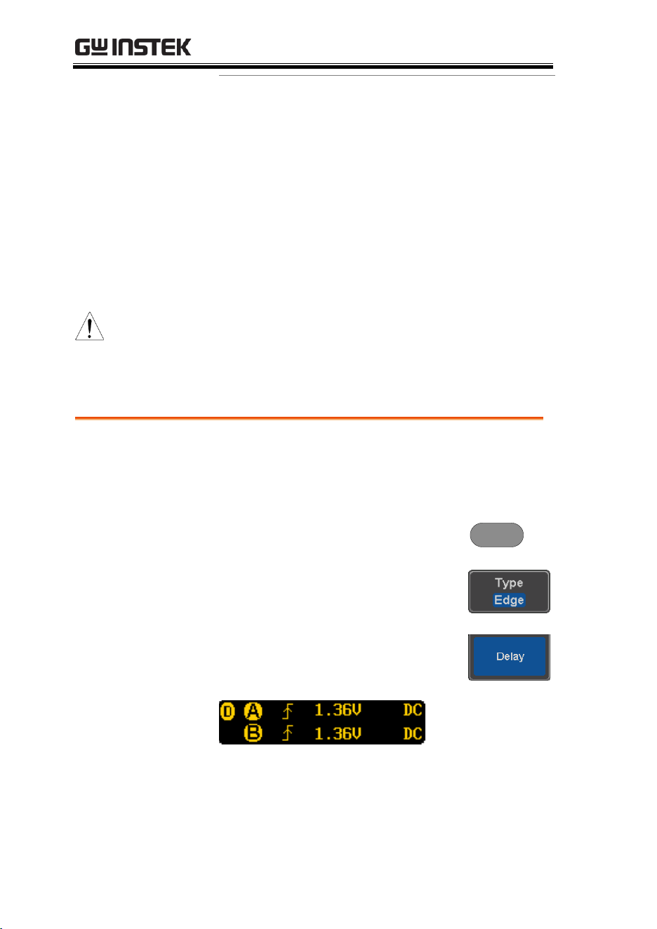
The delay trigger indicator appears
at the bottom of the display.
From left: Delay trigger indicator (D),
edge trigger (A), edge slope, edge level, edge
coupling, delay trigger (B), delay slope, delay
trigger level, delay coupling.
Loading ...
Loading ...
Loading ...