Pack contains ............................................................................................1
Installaon - Programmer .......................................................................... 1
Mounngofwallmoungplate .......................................................................................1
Installingbaeries ........................................................................ .....................................1
Wiring ...............................................................................................................................1
MounngoftheProgrammer ...........................................................................................2
Installaon - Thermostat ...........................................................................2
Installingbaeries ........................................................................ .....................................2
Mounngofthermostat ....................................................................................................2
Pairingprocedure ..............................................................................................................3
Installer sengs ........................................................................................3
Advancedinstallerseng .................................................................................................3
Technical specicaons .............................................................................4
PRG7RFB NEO ENG CP V01 01 07 2021
TABLE OF CONTENTS
1
INSTALLATION INSTRUCTIONS
For best performance, do not mount the programmer on metal wall boxes and leave at
least 30 cm distance from any metal objects including wall boxes and boiler housing.
The digital programmer is xed on the wall with the wall plate which is supplied with
the product.
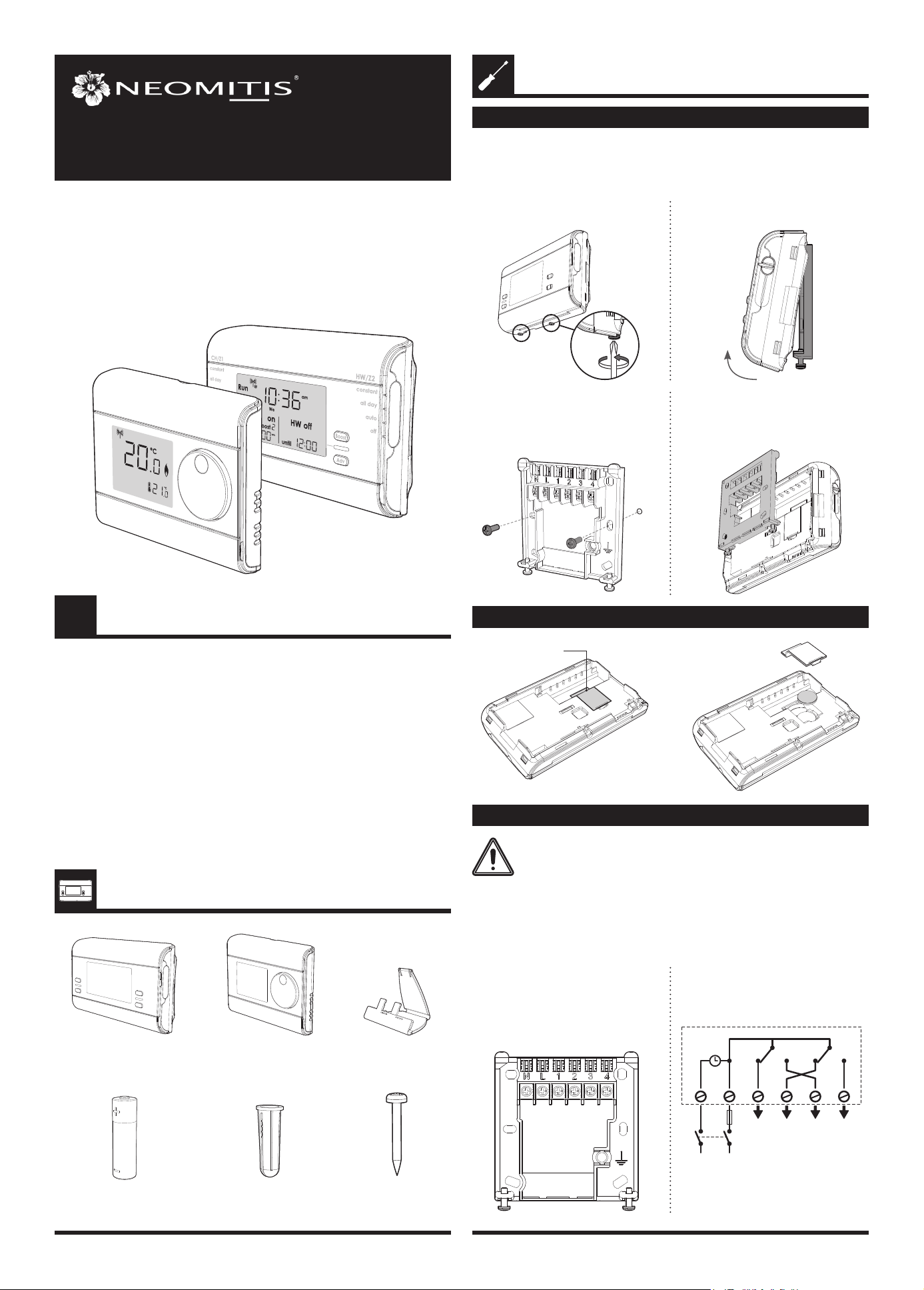
MOUNTING OF WALL MOUTING PLATE
INSTALLING BATTERY
INSTALLATION - PROGRAMMER
PACK CONTAINS
WIRING
All wiring must be in accordance with IEE regulaons. This product is for xed wiring
only.
All electrical installaon work should be carried out by a suitably qualied
Electrician or other competent person. If you are not sure how to install
this programmer consult either with a qualied electrician or heang En-
gineer. Do not remove or ret the appliance onto the backplate without
the mains supply to the system being isolated.
x4
Screw Anchor
x4
Screws
x2
AA Baeries (LR6)
x1
Programmer
x1
Thermostat
x1
Thermostat table stand
• Internal wiring
PRG7 RF
7 DAY TWO CHANNEL PROGRAMMER
WITH RF ROOM THERMOSTAT
2- Remove the wall plate from the
programmer.
1- Unscrew the 2 screws under the
programmer.
x2
3- Secure the wall plate with the two
screws provided using the horizontal
and vercal holes.
4- In case of surface mounng, a knock
out area is provided on the wall plate
and on the corresponding area of the
programmer.
Programmer baery
access
N = Neutral IN
L = Live IN
1 = HW/Z2: Normal close output
2 = CH/Z1: Normal close output
3 = HW/Z2: Normal open output
4 = CH/Z1: Normal open output
HW
OFF
LN
N L 1 2 3 4
220V-240V~
50Hz
6A
max
CH
OFF
HW
ON
CH
ON
OFFClock OFF ONON
Note: The unit is double in insulated so
does not require an earth but a terminal
is supplied for the spare wire.
2
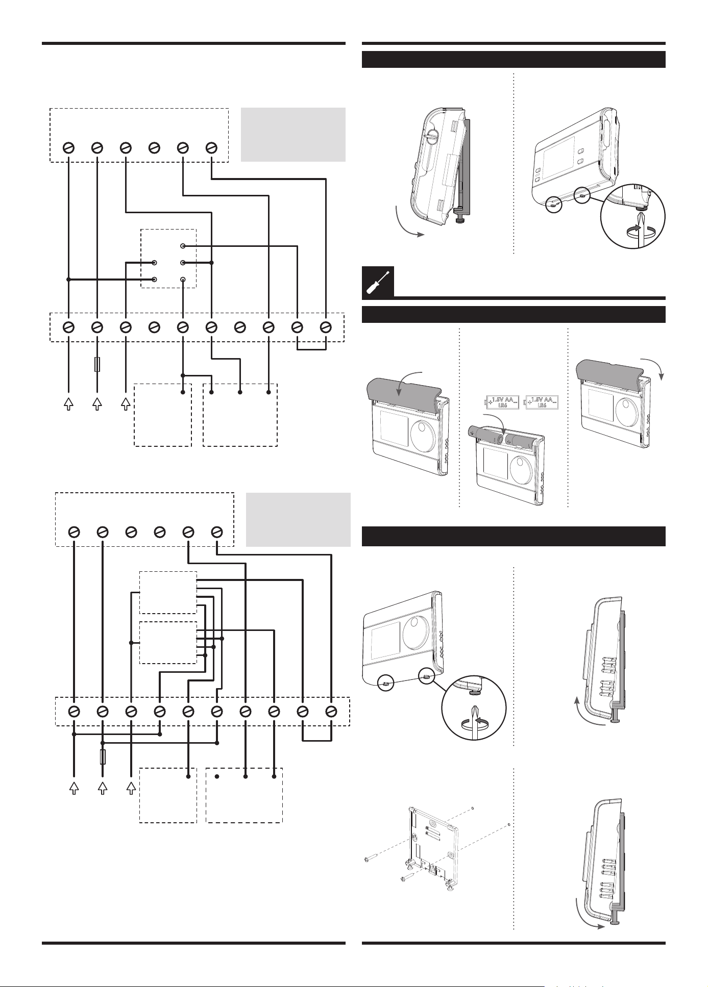
• Wiring diagrams
3 port system
2 port system
MOUNTING OF THE PROGRAMMER
N L 1 2 3 4
L EN
N L 3 4 5 7 8 9 106
3A
max
PRG7RF
2 Channel programmer
Cylinder
Thermostat
CTHa
Boiler
and Pump
connections
Mid position
valve
Junction Box
B
G/Y
O
W
Gr
220V-240V~
50Hz
Switched live 12 3
W = White
Gr = Grey
O = Orange
G/Y = Green/Yellow
B = Blue
3 21
N L 1 2 3 4
L EN
N L 3 4 5 7 8 9 106
3A
max
PRG7RF
2 Channel programmer
Cylinder Thermostat
CTHa
Boiler
and Pump
connections
B
G/Y
O Gr Br Br
220V-240V~
50Hz
Junction Box
Zone valve
Zone valve
Br = Brown
Gr = Grey
O = Orange
G/Y = Green/Yellow
B = Blue
1- Replace the programmer on the wall
mounng plate.
2- Secure the programmer by screwing
both locking screws under the pro
-
grammer.
INSTALLING BATTERIES
INSTALLATION - THERMOSTAT
1- Remove the baeries
cover which is placed
on the front of ther-
mostat.
2- Insert the 2 baeries AA
supplied. Note the cor-
rect polarity according
to the engraving on the
thermostat when inser-
ng the baeries.
3- Replace the baeries
cover.
• On the wall
MOUNTING OF THERMOSTAT
1- Unscrew the 2 screws under the
thermostat.
2- Remove the wall plate from the
thermostat.
x2
3- Secure the wall plate with the two
screws provided using the horizontal
and vercal holes.
4- Replace the thermostat on the wall
mounng plate.
x2
3
• On the table stand
5- Secure the thermostat by screwing the
locking screws under the thermostat.
x2
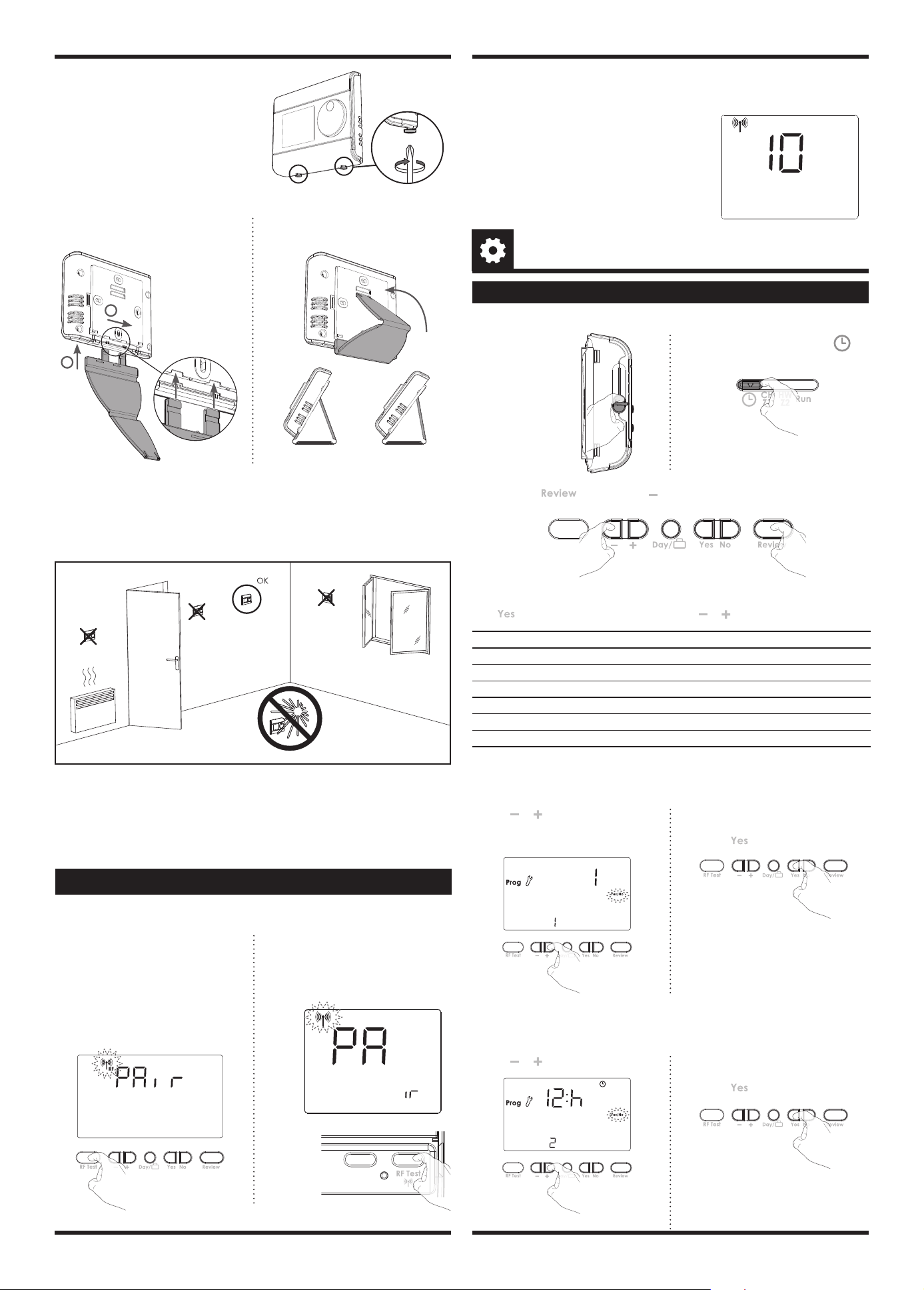
Recommended locaons for your thermostat.
To ensure that your thermostat provides accurate readings and controls eecvely, it
must be installed approximately 1.5 m above oor level on
an inside wall, away from direct sunshine and any other sources of heat or cold such as
radiators, cold draughts, etc.
1- Insert the 2 pins inside the wallplate
and slide on the stand .
2
1
2- Fold the stand and lock it into the
wallplate.
2 lts possibilies
30° 37°
NB: In order to ensure proper operaon of the product, ensure that the thermostat is
not posioned near to an area which could be aected by
interference from another source. E.g.: a wireless transmier or receiver, TV, PC, etc.
Important: The thermostat measures the temperature of the place where
it is installed. It does not take into account the temperature dierences that may exist
between dierent locaons in the house if the temperature is not uniform.
• Access
ADVANCED INSTALLER SETTING
INSTALLER SETTINGS
Move the 2 mode
sliders to o posi-
on.
Move the programming slider to
posion.
x2
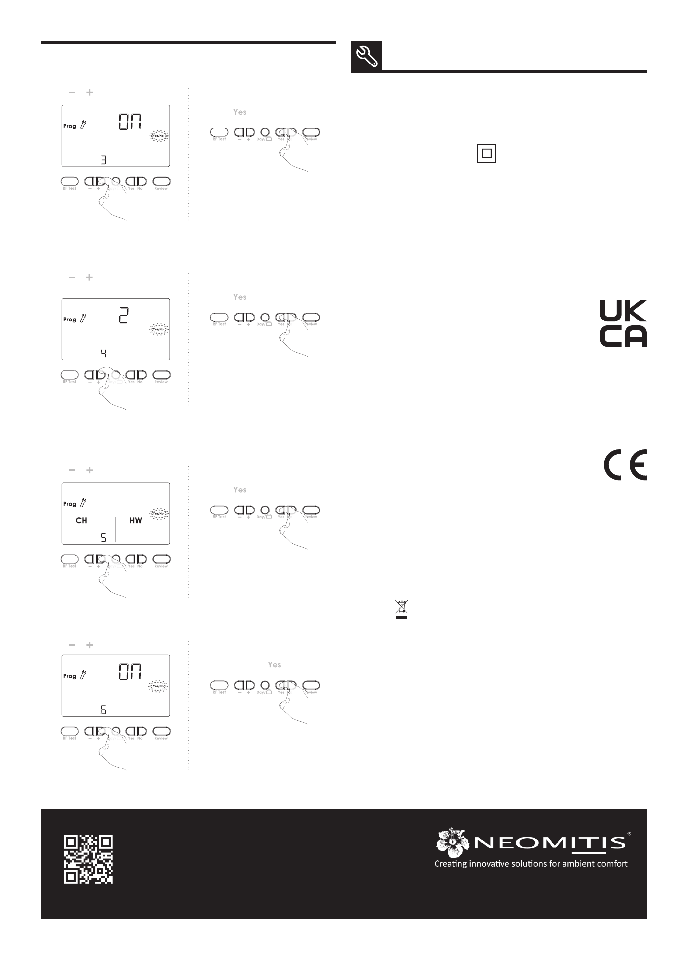
Seng number Descripon
1 Select gravity/pumped mode
2 Set 12 or 24 hours clock
3 Acvaon of auto Summer/Winter change over
4 Set the number of ON/OFF periods
5 Select your system between Z1/Z2 or CH/HW
6
Acvaon of backlight
6 advanced sengs can be modied.
Press unl correct opon is in display then use or to select your choice.
Press and hold and then press and hold both down unl spanner is in
display.
Note: the programmer is usually located near your
boiler. If you want to check the signal strength,
press and release the RF test buon on the ther-
mostat. RF icon blinks for 10 seconds then signal
strength appears. 10 is the best signal strength.
OK
Boost
Prog
1 2 3
GO
PAIRING PROCEDURE
The programmer and the thermostat are not bonded together at the factory.
To bond the programmer and the thermostat together, proceed as below:
2- Within 1 minute, press and hold the
RF Test buon on the thermostat
unl PAir is shown in the display
(approx. 5 seconds). The pairing Icon
will be ashing.
C
C
5 sec
OK
Boost
Prog
1 2 3
GO
1- Move the 2 mode sliders on both
sides of the programmer to the OFF
posion and then move the program
slider to the RUN posion. Once this
is done, press and hold the RF test
buon unl Pair is shown in the dis-
play (approx. 5 seconds). The pairing
icon will be ashing.
5 sec
3- Programmer and Thermostat RF icon will be solid when pairing is complete and
normal display is returned.
• Gravity/Pumped mode (1)
The pre-set system is Pumped.
2- Then save by moving the programming
slider or save and go to next seng by
pressing
.
1- Press or to change to Gravity (2).
1 = Pumped
2 = Gravity
• Set 12/24 hours clock (2)
The pre-set value is 12 hours clock.
2- Then save by moving the programming
slider or save and go to next seng by
pressing
.
1- Press or to change to "24h".
Registered trademarks - All rights reserved
4
www.neomitis.com
NEOMITIS® LIMITED - 16 Great Queen Street, Covent Garden, London, WC2B 5AH UNITED KINGDOM
Registered in England and Wales No: 9543404
Tel: +44 (0) 2071 250 236 - Fax: +44 (0) 2071 250 267 - E-mail: contactuk@neomis.com
EU declaraon of conformity: We, Imhotep Creaon, hereby declare
under our sole responsibility that the products described in these
instrucons comply with the provisions of Direcves and harmonized
standards listed below:
- RED:
- Arcle 3.1a (Safety): EN60730-1:2011 / EN60730-2-7:2010/ EN60730-2-9: 2010 /
EN62311:2008
- Arcle 3.1b (EMC): ETSI EN 301 489-1 V2.2.1 (2019-03) / ETSI EN 301 489-3 V2.1.1
- Arcle 3.2 (RF): ETSI EN 300440 V2.1.1 (2017)
Imhotep Creaon: ZI Montplaisir - 258 Rue du champ de courses - 38780 Pont-Evêque -
France - contact@imhotepcreaon.com
Neomis Ltd and Imhotep Creaon belong to Axenco Group.
• Auto Summer/Winter change over (3)
The auto Summer/Winter change over default is ON.
2- Then save by moving the programming
slider or save and go to next seng by
pressing
.
1- Press or to change to OFF
• Installaon operang (5)
• Backlight (6)
The digital programmer can manage Central Heang and Hot Water or 2 zones. The
pre-set choice is CH/HW.
The backlight can be switched O. The pre-set value is ON.
Note regarding the Advanced installer sengs: If programming slider is moved, it will
save changes and exit installer mode.
2- Then save by moving the programming
slider or save and go to next seng by
pressing
.
1- Press or to change to Z1/Z2.
2- 2. Then save by moving the program-
ming slider or save and go to next
seng by pressing .
1- Press or to change to OFF.
• Set number of ON/OFF periods (4)
You can adjust the number of ON/OFF switching me periods. The pre-set number is 2.
2- Then save by moving the programming
slider or save and go to next seng by
pressing
.
1- Press or to change to 3 periods.
TECHNICAL SPECIFICATIONS
Programmer
- Power supply: 220V-240V/50Hz.
- Output per relay: 3(2)A, 240V/50Hz.
- Rated impulse voltage: 4000V.
- Micro disconnecon: Type 1B.
- Polluon degree: 2.
- Automac acon: 100,000 cycles.
- Class II.
Environment:
- Operaon temperature: 0°C to +40°C.
- Storage temperature: from -20°C to
+60°C.
- Humidity: 80% at +25°C (without
condensaon).
- Protecon rang: IP30.
Thermostat
- Manual temperature seng range: from
+5°C to +30°C.
- Power supply: 2 alkaline 1.5 V AA (LR6)
baeries.
- Baery life: approx. 2 years.
Maximum range in the home: 15m is
typical but this varies depending on the
building construcon E.g. plasterboard
lined with metal foil, the number of walls
and ceilings that the signal has to pass
through, and by the surrounding electro
-
magnec environment.
Signal sending: every 10 minutes, maxi
-
mum me-lag 1 minute aer setpoint
temperature has been changed.
Environment :
- Operaon temperature: 0°C to +40°C.
- Storage temperature: from -10°C to
+60°C.
- Humidity: 80% at +25°C (without
condensaon)
- Protecon rang: IP30.
The symbol , axed on the product indicates that you must dispose of it at the end
of its useful life at a special recycling point, in accordance with European Direcve WEEE
2012/19/EU. If you are replacing it, you can also return it to the retailer from which you
buy the replacement equipment. Thus, it is not ordinary household waste. Recycling
products enables us to protect the environment and to use less natural resources.
UKCA declaraon of conformity: We, Neomis Ltd, hereby declare
under our sole responsibility that the products described in these
instrucons comply with statutory instruments 2017 No. 1206 (Radio
Equipment Regulaons), 2012 n°3032 (ROHS) and following designated
standards listed below:
- 2017 No. 1206 (Radio Equipment Regulaons):
- Arcle 3.1a : EN 60730-1:2011, EN 60730-2-7:2010/AC:2011, EN 60730-2-9:2010,
EN 62311:2008
- Arcle 3.1b : EN 301489-1 V1.9.2
- Arcle 3.2 : EN 300440 V2.1.1
- The Restricon of the Use of Certain Hazardous Substances in Electrical and Electronic
Equipment Regulaons 2012 (2012 No.3032) : EN IEC 63000:2018.
Neomis Ltd: 16 Great Queen Street, Covent Garden, London, WC2B 5AH UNITED
KINGDOM - contactuk@neomis.com
- RoHS 2011/65/UE, amended by Direcves 2015/863/UE & 2017/2102/UE : EN IEC
63000:2018
Overview ......................................................................................................... 1
Controls and display ........................................................................................ 1
Programmer ...................................................................................................................... 1
Thermostat ........................................................................................................................1
Sengs ........................................................................................................... 1
Inialpowerup ................................................................................................................1
Pairingprocedure .............................................................................................................2
Programming ................................................................................................... 2
SettheCH/Z1andHW/Z2programming ..........................................................................2
Operang ........................................................................................................ 3
Modeseleconanddescripon ........................................................................................3
Boost .................................................................................................................................3
Advance .............................................................................................................................3
Holiday ..............................................................................................................................3
Review ...............................................................................................................................3
Temperatureseng ..........................................................................................................3
Factorysengs .................................................................................................................4
Setdateandclock .............................................................................................................4
Troubleshoong .............................................................................................. 4
Technical specicaons ................................................................................... 4
Note ................................................................................................................ 4
What is a programmer ? .................................................................................. 4
What is PID ...................................................................................................... 4
PRG7RFB NEO ENG CP V01 01 07 2021
7 DAY TWO CHANNEL PROGRAMMER
WITH RF ROOM THERMOSTAT
TABLE OF CONTENTS
1
OPERATING
INSTRUCTIONS
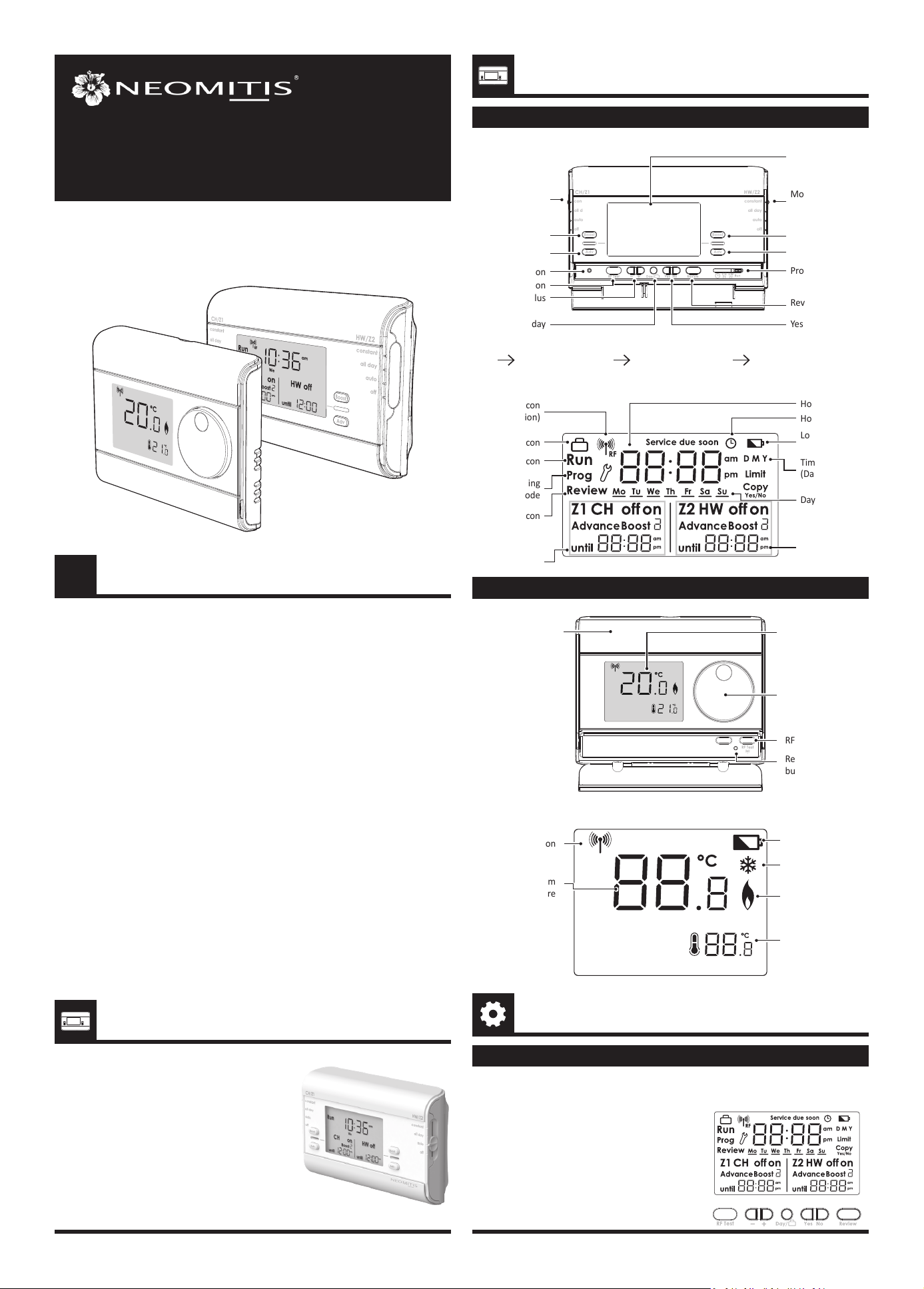
• LCD Display
CONTROLS AND DISPLAY
Programming sliders sequences:
Time CH/Z1 programming HW/Z2 programming Run
OVERVIEW
Thank you for purchasing our PRG7 RF, wireless 7
day digital programmer with digital thermostat.
It is by listening to your requirements we have
created and designed our products to be easy to
operate and install.
It is this ease of operaon that is intended to make
your life easier and help you save energy and
money.
constant
all day
auto
off
constant
all day
auto
off
Mode slider
CH/Z1
Boost CH/Z1
Advance CH/Z1
Reset buon
Mode slider HW/Z2
Boost HW/Z2
Advance HW/Z2
LCD display
Minus/Plus
RF test buon
Day/Holiday Yes/No
Review
Programming slider
Pairing icon
(RF version)
Holiday icon
Run icon
Review icon
CH/Z1 status
Programming
mode
Advanced
sengs
Hour
Days
Hour seng
HW/Z2 status
Low baery icon
Time seng
(Day, Month, Year)
PROGRAMMER
THERMOSTAT
Baeries
compartment
Rotary dial
Reset
buon
LCD display
RF test buon
• LCD Display
• Programmer
Measured room
temperature
Pairing icon
Low baery icon
Frost protecon
icon
Call for heat
icon
Temperature
setpoint
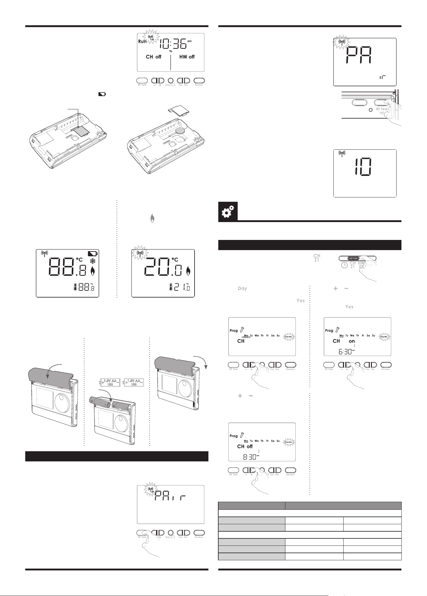
INITIAL POWER UP
SETTINGS
1- Switch on the programmer power
supply.
All symbols will be displayed on the
LCD screen as shown for two seconds.
PRG7 RF
2
SET THE CH/Z1 AND HW/Z2 PROGRAMMING
On/O periods Default schedule
Two On/O periods sengs
Period 1 Start at 06:30
am
End at 08:30
am
Period 2 Start at 05:00
pm
End at 10:00
pm
Three On/O periods sengs
Period 1 Start at 06:30
am
End at 08:30
am
Period 2 Start at 12:00
pm
End at 02:00
pm
Period 3 Start at 05:00
pm
End at 10:00
pm
1- Move the Programming slider to posion .
All days of week are solid. Underscore and Yes/
No are ashing.
4- Press or to increment/decre-
ment the rst On/O period end
me.
Then press Yes to conrm.
5- Repeat for the second On/O period
and for the third On/O period.
(Please refer to the advanced installer
sengs on Installaon instrucon to
enable the third On/O period).
2- Press if you want to set an other
day of the week. Underscore moves
under the other days. Then press
to program the underscored day.
3- Press or to increment/decre-
ment the rst On/O period start
me.
Then press to conrm.
PROGRAMMING
Note : The PRG is already set with correct date and me. Should programmer need
reseng for any reasons, please see instrucons on page 4.
• Thermostat
- Installing baeries
Note: When the baeries must be changed, a low baery level indicator appears on the
device.
Remember to take used baeries to baery collecon points so they can be recycled.
1- To start: insert the two AA baeries
provided into the baery compart
-
ment.
Once baeries are ed all symbols
will be displayed on the LCD screen as
shown for two seconds.
2- Aer 2 seconds, the LCD will show:
- The ambient temperature (°C) solid.
- The icon
is solid when the heang
is turned ON.
- The setpoint temperature (°C) solid.
- RF icon ashes.
OK
Boost
Prog
1 2 3
GO
OK
Boost
Prog
1 2 3
GO
PAIRING PROCEDURE
The thermostat and the programmer are not bonded together at the factory.
To bond the thermostat and the programmer together, proceed as below:
2- Within 1 minute, press and hold the RF Test
buon on the thermostat unl PAir is shown
in the display (approx. 5 seconds). The pairing
Icon will be ashing.
C
C
5 sec
OK
Boost
Prog
1 2 3
GO
1- Move the 2 mode sliders on both sides of the
programmer to the OFF posion and then
move the program slider to the RUN posion.
Once this is done, press and hold the RF
test buon unl Pair is shown in the display
(approx. 5 seconds). The pairing icon will be
ashing.
5 sec
3- Programmer and Thermostat RF icon will be solid when pairing is complete and
normal display is returned.
2- Aer 2 seconds, the LCD will show:
- The default me and day
- Run icon solid
- CH and HW systems are OFF
- RF icon ashes
Note: the programmer is usually located near your
boiler. If you want to check the signal strength,
press and release the RF test buon on the ther-
mostat. RF icon blinks for 10 seconds then signal
strength appears. 10 is the best signal strength.
OK
Boost
Prog
1 2 3
GO
Note: A low baery level indicator will appear in the display when the baery must
be changed.
Remember to take used baeries to a baery collecon point so they can be recycled.
Programmer baery
access
1- Remove the baeries
cover which is placed
on the front of ther-
mostat.
2- Insert the 2 baeries AA
supplied. Note the cor-
rect polarity according
to the engraving on the
thermostat when inser-
ng the baeries.
3- Replace the baeries
cover.
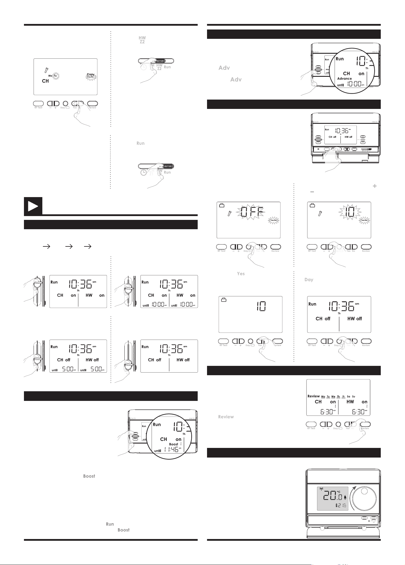
ADVANCE
3
7- Slide the programming slider to
posion to conrm and program
the second channel.
6- The current program can be copy to
the next days. Press Yes to copy or No
to program manually the next day.
8- Repeat the previous step to program
On/O period for HW/Z2.
9- When nished, move the program
slider to posion to conrm.
OPERATING
MODE SELECTION AND DESCRIPTION
Mode sliders sequences for CH/Z1 and HW/Z2:
Constant all day auto o
BOOST
BOOST: Boost mode is a temporary mode
which allows you to switch ON for 1, 2 or 3
hours. At the end of set period the device
will revert to its prior seng.
constant
all day
auto
off
constant
all day
auto
off
BOOST will work from any running mode.
BOOST is entered by pressing buon for corresponding system (CH/Z1 or HW/
Z2).
Press 1 me to set 1 hour, 2 mes to set 2 hours and 3 mes to set 3 hours.
Note:
- The Programming slider must be in the
posion.
- There will be a slight delay between pressing and acvaon of the relay.
BOOST is cancelled by pressing again on Boost or movement of sliders.
When BOOST is running the end of Boost period is shown for each system.
Advance: advance mode is a temporary
mode which allows you to switch ON the
system in advance, unl the next On/O
period end me.
Press
buon of corresponding chan-
nel to acvate this mode.
Press again buon to disable it before
the end.
constant
all day
auto
off
constant
all day
auto
off
HOLIDAY
Holiday: Holiday mode allows to switch o
the heang (or Z1) and hot water (or Z2) for a
specied number of days, adjustable between 1
and 99 days.
constant
all day
auto
off
constant
all day
auto
off
To set the holiday funcon:
3- Then press
to conrm. the
heang (or Z1) and hot water (or Z2)
switch O and the number of remai-
ning days will count down on display.
4- To cancel the holiday funcon, press
buon.
1- Press Day buon for 5 seconds.
2- OFF appears on the display. Press
or to increment or decrement the
number of days.
5 sec.
REVIEW
Press buon to start the programming
review.
Press again to go back on normal operang
mode.
Review: Review mode allows to review all
programming in one me. The review starts
from the beginning of the week and each
steps appears each 2 seconds.
Constant: Permanent ON mode. The
system is permanently turned ON.
All day: The system turn ON from the
rst On period start me unl the last O
period end me of the current day.
Auto: Automac mode. The unit is
controlling to the programming that have
been selected (refer to "Programming"
secon page 2).
O: Permanent O mode. The system
stays O permanently. The boost mode
can be sll used.
TEMPERATURE SETTING
The desired temperature can be set.
1- To set the temperature, turn the dial clo
-
ckwise, to increment the temperature, turn
the dial counter-clockwise, to decrement the
temperature.
The default temperature is 20°C (68°F).
Registered trademarks - All rights reserved
4
www.neomitis.com
NEOMITIS® LIMITED - 16 Great Queen Street, Covent Garden, London, WC2B 5AH UNITED KINGDOM
Registered in England and Wales No: 9543404
Tel: +44 (0) 2071 250 236 - Fax: +44 (0) 2071 250 267 - E-mail: contactuk@neomis.com
Sengs Factory sengs
Two On/O periods sengs
Period 1 Start at 06:30
am
End at 08:30
am
Period 2 Start at 05:00
pm
End at 10:00
pm
Three On/O periods sengs
Period 1 Start at 06:30
am
End at 08:30
am
Period 2 Start at 12:00
pm
End at 02:00
pm
Period 3 Start at 05:00
pm
End at 10:00
pm
FACTORY SETTINGS
• Programmer
Note: To restore factory set-
ngs, press and hold down this
part for more than 3 seconds
using the p of a pen.
constant
all day
auto
off
constant
all day
auto
off
3 sec.
All LCD display will be turned ON for 2 seconds and the factory sengs will be restored.
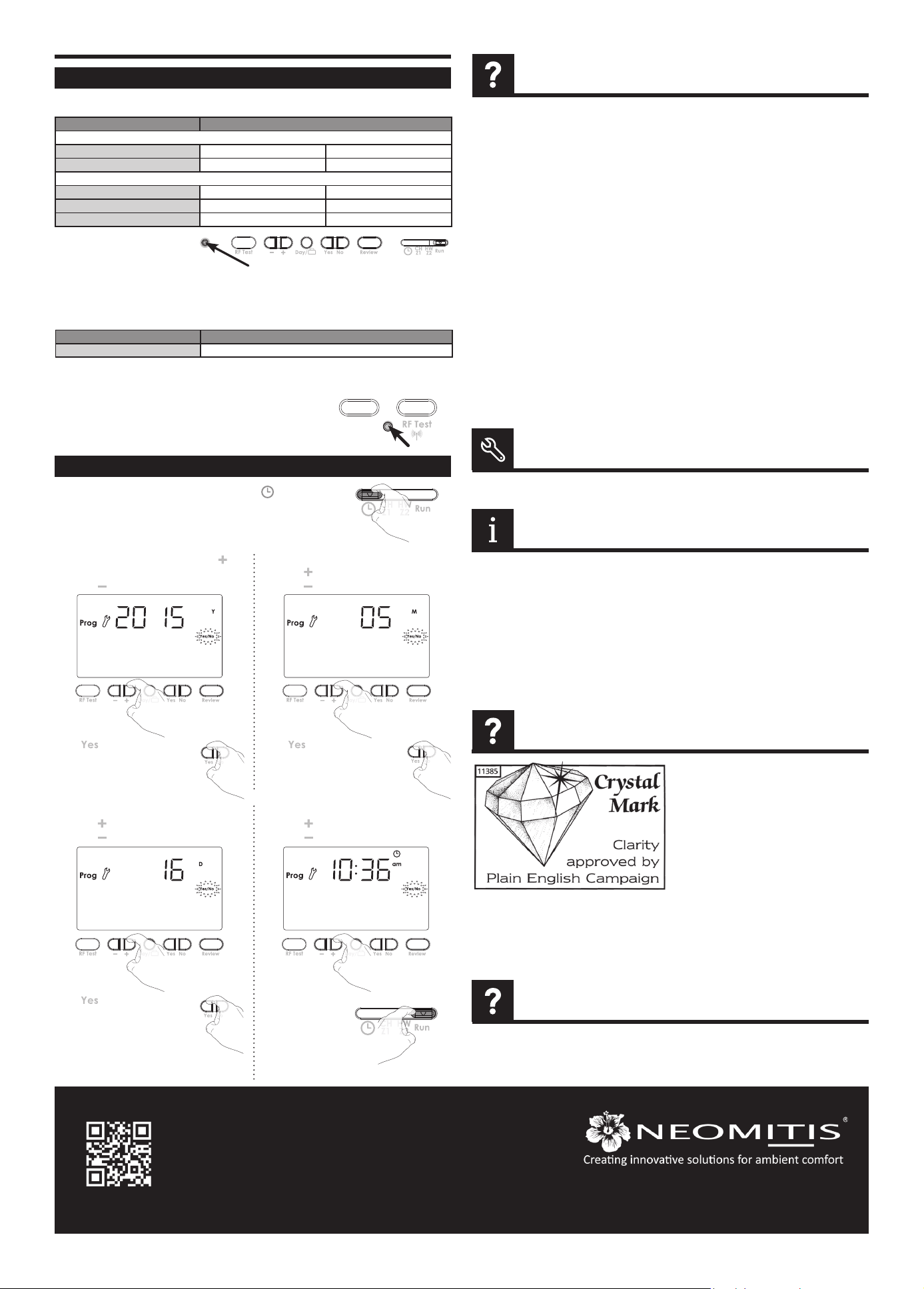
01 = January ; 02 = February
; 03 = March ; 04 = April ; 05
= May ; 06 = June ; 07 = July
; 08 = August ; 09 = September ; 10 = Oc
-
tober ; 11 = November ; 12 = December
SET DATE AND CLOCK
1- Move the Programming slider to posion .
Preset year is solid.
Display disappears on programmer:
- Check fused spur supply.
Heang does not come on:
- If the CH Indicator light is on then it is unlikely
to be a fault with the programmer.
- If CH indicator light is NOT ON then check pro-
gramme then try BOOST as this should ope-
rate in any posion.
- Check that your room thermostat is calling for
heat.
- Check that the boiler is on.
- Check that your pump is working.
- Check that your motorised valve if ed has
opened.
Hot water does not come on:
- If the HW Indicator light is on then it is unlikely
to be a fault with the programmer.
- If HW indicator light is NOT ON then check
programme then try BOOST as this should
operate in any posion.
- Check that your Cylinder thermostat is calling
for heat.
- Check that the boiler is on.
- Check that your pump is working.
- Check that your motorised valve if ed has
opened.
The boiler is not heang:
- Check that the thermostat is calling for heat if
yes then the thermostat would appear to be
working check that the boiler has not switched
itself o. If no increase set temperature.
- Check the posion of the baeries. Remove
them for 30 seconds and reinsert them. If the
problem persists, replace the 2 baeries.
Nothing in the display:
- Check the posion of the baeries. Remove
them for 30 seconds and reinsert them. If the
problem persists, replace the 2 baeries.
The room temperature is not high enough, the
boiler is not providing enough heat:
- Check the acve desired temperature and in-
crease it if need be (see page 3).
You made a mistake while seng:
- You just need to restore factory sengs, as ex
-
plained in the “Factory sengs” secon (see
page 4). This will reverse any changes you mi
-
ght have made.
The system is not heang but is on:
- If and indicator light is on but the system remains
cold, then you should contact your installer.
If the problem persists contact your installer.
Note: If Service due soon or service due appears
in display please contact your landlord.
...an Explanaon for Householders. Program
-
mers allow you to set ‘On’ and ‘O’ me pe-
riods. Some models switch the central heang
and domesc hot water on and o at the same
me, while others allow the domesc hot water
and heang to come on and go o at dierent
mes. Set the ‘On’ and ‘O’ me periods to suit
your own lifestyle. On some programmers you
must also set whether you want the heang
and hot water to run connuously, run under
the chosen ‘On’ and ‘O’ heang periods, or be
permanently o. The me on the programmer
must be correct. Some types have to be adjusted
in spring and autumn at the changes between
Greenwich Mean Time and Brish Summer
Time. You may be able to temporarily adjust the
heang programme, for example, ‘Advance’, or
‘Boost’. These are explained in the manufactu
-
rer’s instrucons. The heang will not work if
the room thermostat has switched the heang
o. And, if you have a hot-water cylinder, the
water heang will not work if the cylinder ther
-
mostat detects that the hot water has reached
the correct temperature.
Please refer to the installing instrucons for any informaons about standards and product envi-
ronment.
The PID feature works by using a formula to calculate the dierence between the desired tempera
-
ture setpoint and current ambient temperature, the PID feature then predicts how much power to
use to ensure the ambient temperature remains as close to the temperature setpoint as possible by
eliminang the impact of environmental temperature changes.
• Thermostat
Note: To restore factory sengs, press and hold down this part for more than 3
seconds using the p of a pen.
All LCD display will be turned ON for 2 seconds and
the factory sengs will be restored.
C
C
Sengs Factory sengs
Set temperature 20°C
5- The preset me appears.
Press to increment the me.
Press to decrement the me.
Move the program
slider to any
other posion to
conrm/nish this
seng.
4- The preset day appears.
Press to increment the day.
Press to decrement the day.
Press to conrm and set
the clock.
TROUBLESHOOTING
TECHNICAL SPECIFICATIONS
WHAT IS PID
In some instances the unit may have been set with
the service interval funcon enabled.
By Law in rented accommodaon, your gas boi-
ler should be inspected/serviced annually to en-
sure it is working correctly.
This opon is designed to remind the end user to
contact the relevant person to have the annual
service carried out on the boiler.
This funcon will be enabled and programmed
by your Installer, maintenance Engineer, or Lan
-
dlord.
If it has been set to do so, the unit will display
a message on the screen to remind you that a
boiler service is due.
The Service Due Soon countdown will be indi
-
cated up to 50 days before the Service is due to
allow me to arrange for an engineer to aend,
normal funcons will connue during this stage.
At the end of this service due soon period, the
unit will go to Service Due OFF at which point
only the 1hour boost will operate on TMR7 and
PRG7, if the unit is a thermostat RT1/RT7, it will
operate at 20°C during this hour.
If PRG7 RF, Thermostat has no funcon.
NOTE
WHAT IS A PROGRAMMER ?
Press to conrm and set
the current month.
Press to conrm and set
the current day.
2- To select the current year, press , to
increment the year.
Press , to decrement the year.
3- The preset month appears.
Press to increment the month.
Press to decrement the month.
