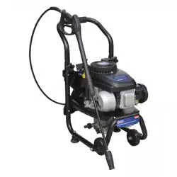
PRESSURE WASHER 150BAR 360LTR/HR 4HP PETROL
MODEL NO: PWM1300.V2
Thank you for purchasing a Sealey product. Manufactured to a high standard, this product will, if used according to these instructions,
and properly maintained, give you years of trouble free performance.
IMPORTANT: PLEASE READ THESE INSTRUCTIONS CAREFULLY. NOTE THE SAFE OPERATIONAL REQUIREMENTS, WARNINGS & CAUTIONS. USE
THE PRODUCT CORRECTLY AND WITH CARE FOR THE PURPOSE FOR WHICH IT IS INTENDED. FAILURE TO DO SO MAY CAUSE DAMAGE AND/OR
PERSONAL INJURY AND WILL INVALIDATE THE WARRANTY. KEEP THESE INSTRUCTIONS SAFE FOR FUTURE USE.
1. SAFETY
1.1. GENERAL SAFETY
WARNING! RISK OF FLUID INJECTION. This washer operates at fluid pressures and velocities high enough to penetrate human and
animal flesh. If there is an occurrence of fluid injection seek medical help immediately.
WARNING! Stop the engine and disconnect the mains water supply before changing accessories or performing any maintenance.
WARNING! DO NOT operate the washer if damaged. Replace or repair using recommended parts only. Unauthorised parts may
be dangerous and will invalidate your warranty. Use authorised Service agent only.
9 Keep the washer in good condition. Regular maintenance will give the best and safest performance.
9 Ensure you comply with the water supply company regulations before connecting to the mains. If you are connecting to the mains
drinking water supply ensure you have a back flow preventer valve installed.
9 The water supply hose must be reinforced and have an internal diameter of 13mm (1/2”). The minimum water supply rate must be at
least equal to the cleaner capacity. The water temperature must not exceed 40°C, and the pressure must not exceed 10bar.
WARNING! DO NOT operate the washer without the water supply connected. To do so will damage the machine.
9 Position the washer as near as possible to the mains water supply.
9 Only use recommended washing detergents. Failure to do so may cause corrosion to equipment and hoses.
WARNING! Use the washer on a at, level surface, in a horizontal position. Failure to do so will invalidate your warranty.
9 Wear safety goggles and adequate protective clothing, and anti-slip rubber soled footwear.
WARNING! The high pressure jet must be used with caution. Ensure you aim the lance correctly at the work surface. Failure to do so may
scatter loose particles at the same force as the water pressure, resulting in possible damage or personal injury.
9 Keep all persons and animals at a safe distance from the hose working area. It is difficult to give an exact safe distance as it will depend
upon your circumstances. We recommend at least 15 metres (16 yards). Also ensure other persons are aware before you start to depress
the washer trigger.
9 Hold the gun firmly for it will tend to “kick” backwards when you first pull the trigger.
8 DO NOT allow children or untrained persons to operate the washer. Children should be supervised to ensure that they DO NOT play with
the machine.
9 The machine can be used by people with reduced physical, sensory or mental capabilities or lack of experience and knowledge if they
have been given supervision or instruction concerning use of the machine in a safe way and understand the hazards involved.
8 DO NOT connect other appliances to the washer inlet or outlet. Only use the supplied or recommended outlet nozzle.
8 DO NOT use the washer if the water supply hose is damaged. Also check that the hose is laid out straight and safely.
8 DO NOT jam the operating trigger in the operating position and DO NOT pull the trigger without holding and aiming the gun correctly.
WARNING! DO NOT attempt to alter the pressure regulating valve as this may cause serious damage.
8 DO NOT move the washer by pulling on the high pressure hose or the mains water supply hose. Use the machine handle.
8 DO NOT direct jet against yourself, other persons or animals, electrical equipment or the machine itself.
WARNING! DO NOT leave the engine running for more that 2 minutes without operating the trigger, as temperature/pressure increase
may damage the sealing system.
8 DO NOT use the washer if you are tired or under the influence of alcohol, drugs or intoxicating medication.
9 Ensure that the hose pressure is discharged before disconnecting the mains water hose.
9 When not in use, disconnect from the water supply. Clean and dry the washer and store in a safe, dry, childproof area.
8 DO NOT allow the machine to become frozen.
1.2. ENGINE SAFETY
WARNING! Check the engine oil level before each start-up. Only use an approved oil and never operate the engine with insucient
oil.
WARNING! DO NOT touch spark plug or plug lead whilst the engine is running; severe, potentially fatal, electric shock may
result.
9 Ensure that only the correct fuel type and grade is used.
Refer to
instruction
manual
Wear eye
protection
Wear ear
protection
Wear
protective
clothing
Wear
protective
gloves
Caution:
Hot surface
Wear
safety
footwear
DO NOT direct
jet against yourself,
others, animals,
electrical equipment or
the machine itself.
WARNING: The engine is shipped without oil.
The pump is shipped with oil. Therefore only
the engine must be lled with the correct type
and quantity of oil.
See section 3 for Oil specications
Original Language Version
© Jack Sealey Limited
PWM1300.V2 Issue 2 (2) 07/12/20
8 DO NOT check ignition system by removing the spark plug or spark plug lead. Use specific tester or contact service agent.
8 DO NOT operate the washer in an enclosed area as the motor exhaust fumes are a health hazard. Always ensure adequate ventilation.
8 DO NOT use the washer with flammable, toxic or corrosive liquids.
8 DO NOT leave the washer unattended whilst operating, and DO NOT remove the fuel cap whilst the engine is running.
8 DO NOT refuel the engine whilst it is running. Stop the engine and allow it to cool for two minutes before attempting to refuel.
8 DO NOT refuel in a closed or poorly ventilated environment as there is a danger of explosion or fire. Refuel out doors.
8 DO NOT smoke or place the washer near any naked flames whilst re-fuelling.
8 DO NOT operate washer if there is a fuel leak. Move the unit and avoid using until the leak has been fixed and the machine is dry.
8 DO NOT start the engine if there are any flammable materials near the exhaust system or in the path of the exhaust gases.
8 DO NOT block the engine ventilation grilles.
9 Ensure engine fuel is stored in an approved container.
9 For long term storage ensure the fuel is drained and that the washer is adequately protected against frost.
8 DO NOT operate the engine with either the silencer or air filter removed.
8 DO NOT touch the engine during or after use. To avoid burns, allow it to cool before handling.
2. INTRODUCTION
Petrol powered pressure washer with recoil starting. Suitable for commercial and domestic applications with 5m pressure hose, gun, lance and
adjustable nozzle. Low-pressure liquid detergent injection system. Safety latch on trigger. Unit stands on two sucker feet to prevent movement and
two wheels for easier mobility with an integral handle. Supplied with tools and full instructions.
3. SPECIFICATION
Model no: ......................................................... PWM1300.V2
Manifold pressure: ...................................... 110bar (1595psi)
Maximum pressure:...................................... 150bar(2175psi)
Flow rate: .................................................................... 6L/min
Hose length: ...................................................................... 5m
Nozzle: ....................................................... adjustable nozzle
Maximum inlet temperature: ........................................... 40°C
Engine type: ............................ 4 stroke, single cylinder petrol
Engine capacity: ........................................................... 141cc
Engine power: .................................................................. 4hp
Starting: ........................................................................ recoil
Fuel tank: ........................................................................... 1L
Fuel consumption: ....................................................0.8-1L/hr
Noise level: ............................................................. 103dB(A)
4. ASSEMBLY AND PREPARATION
Unpack contents and check to ensure all parts are in good condition.
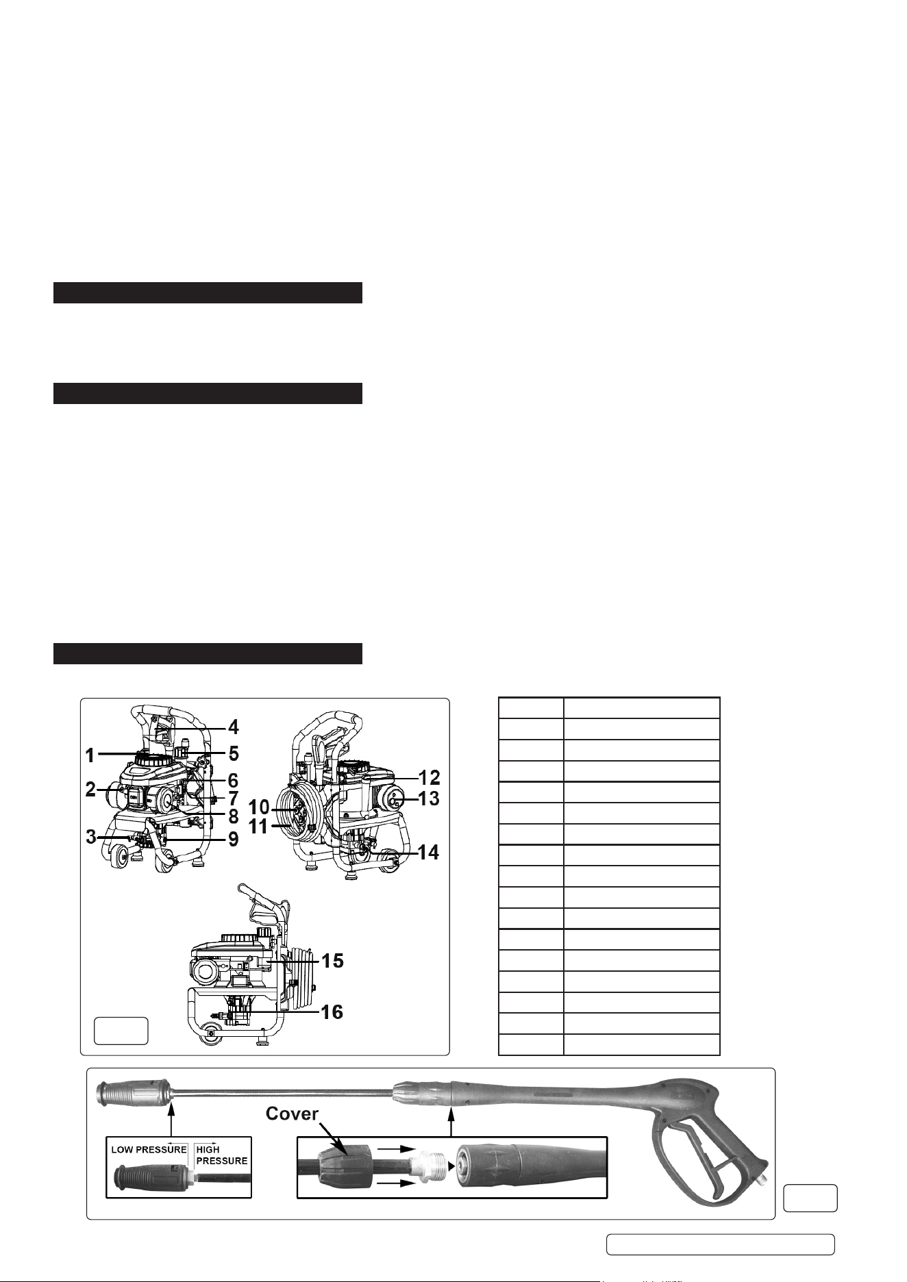
fig.1
fig.2
Item No. Description
1 Starter cord
2 Spark plug
3 Temperature relief valve
4 Spray gun
5 Fuel tank cap
6 Choke control
7 Engine On/O switch
8 Air lter
9 Pump outlet
10 Accessory store
11 Pressure hose
12 Oil dipstick
13 Exhaust
14 Pump inlet
15 Fuel tank
16 Detergent connection
Oil capacity ................................................................... 0.55L
Oil spec. ..............................................................SAE10W-30
Max inlet water pressure ............................................ 0.4MPa
Min inlet water pressure ............................................. 0.2MPa
Original Language Version
© Jack Sealey Limited
fig.1
PWM1300.V2 Issue 2 (2) 07/12/20
4.1. ASSEMBLY
4.1.1. Screw together the two halves of the lance as shown in fig.2. Seal joint by using PTFE tape.
4.1.2. Slide the rubber cover over the connector nut.
4.1.3. Attach the high pressure hose to the water inlet on the gun handle as shown in fig.3A and B. Seal joint by using PTFE tape.
4.1.4. Attach the other end of the high pressure hose to the pump outlet as shown in fig.6. Seal joint by using PTFE tape.
4.1.5. . Connect the mains cold water supply hose to the water inlet as shown in fig.5.
NOTE: The cold water supply hose must be reinforced and have an internal diameter of 13mm (1/2”). The minimum water supply
rate must be at least equal to the washer flow rate.
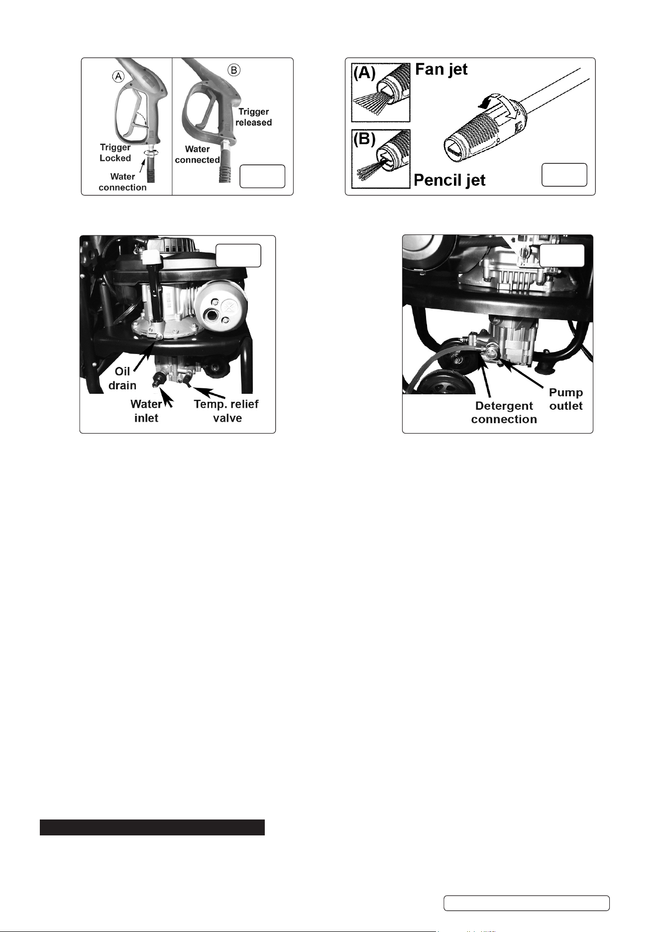
4.2. DETERGENT DELIVERY fig.6
4.2.1. On the side of the pump outlet is a brass siphon injection fitting.
4.2.2. Push the detergent delivery pipe onto the fitting and place the filter on the other end of the pipe into a container of detergent.
4.2.3. When the nozzle on the lance is set to low pressure, detergent will be drawn from the container by siphonic action and will mix
automatically with the water from the pump. Use Sealey General Purpose Detergent, AK130 (25ltr) or AK131 (5ltr). Traffic Film Remover
is also available, AK132 (25ltr) or AK133 (5ltr).
4.3. NOZZLE CONTROL fig.2
4.3.1. PRESSURE. To change from high pressure to low pressure the whole nozzle moves backwards and forwards by about 6mm on the end
of the lance. Pull the nozzle back towards the handle for high pressure and push it away from the handle for low pressure (see fig.2).
4.3.2. SPRAY PATTERN. To change the spray pattern from a pencil jet to a fan jet rotate the nozzle as shown in fig.4.
4.4. ENGINE LUBRICATION
4.4.1. The pressure washer engine is shipped from the factory without oil. DO NOT attempt to start the engine before the sump has been filled
with the correct amount of oil. Oil capacity 0.55L, oil grade SAE10W-30. The dip stick is marked L (Low), H (High).
4.5. FUEL
Fill the petrol tank with fresh unleaded petrol. Tank capacity 1 (one) litre, minimum 87 octane (91 RON).ON)
4.6. TEMPERATURE RELIEF VALVE fig.5
4.6.1. A temperature relief valve is fitted to protect the machine from overheating if the gun remains closed for an extended period of time or if
the nozzle becomes blocked. To prolong the life of the washer every effort should be made to avoid overheating. It is recommended that
if the unit is not to be used for five minutes or more it should be switched off.
4.7. TRIGGER LOCK fig.3
4.7.1. To prevent accidental starting of the pressure washer, the trigger can be locked as shown in fig.3.A by hinging out the lever built
into the back of the trigger and pressing it until it snaps into an indent in the handle. To release the locking lever flex the trigger handle
forwards and flip the lever out of the indent and fold it back into the trigger. The trigger should be locked whenever the washer is not in
use.
5. OPERATION
WARNING! Ensure you read, understand and apply all Section 1 safety instructions.
IMPORTANT Oil has been drained for shipping. Failure to fill engine with oil before starting engine will result in permanent damage and
will void engine warranty.
WARNING! Dry running can seriously damage the unit.
fig.4
fig.3
Original Language Version
© Jack Sealey Limited
fig.5 fig.6
PWM1300.V2 Issue 2 (2) 07/12/20
WARNING! DO NOT leave motor running for more than 5 minutes without operating the trigger, as temperature/pressure increases may
damage sealing system.
5.1. STARTING PROCEDURE
5.1.1. Check engine oil and fuel level before each use. The dip stick is marked L (Low), H (High).
5.1.2. Check that the mains cold water feed hose is laid straight and then fully open the water tap. Check to ensure there are no leaks from
hoses or connections.
5.1.3. Place the detergent input tube into the detergent container. Ensure that the filter goes to the bottom of the container.
5.1.4. Release gun trigger safety catch and depress trigger to allow any air left in the system to escape, hold for 10 seconds and release.
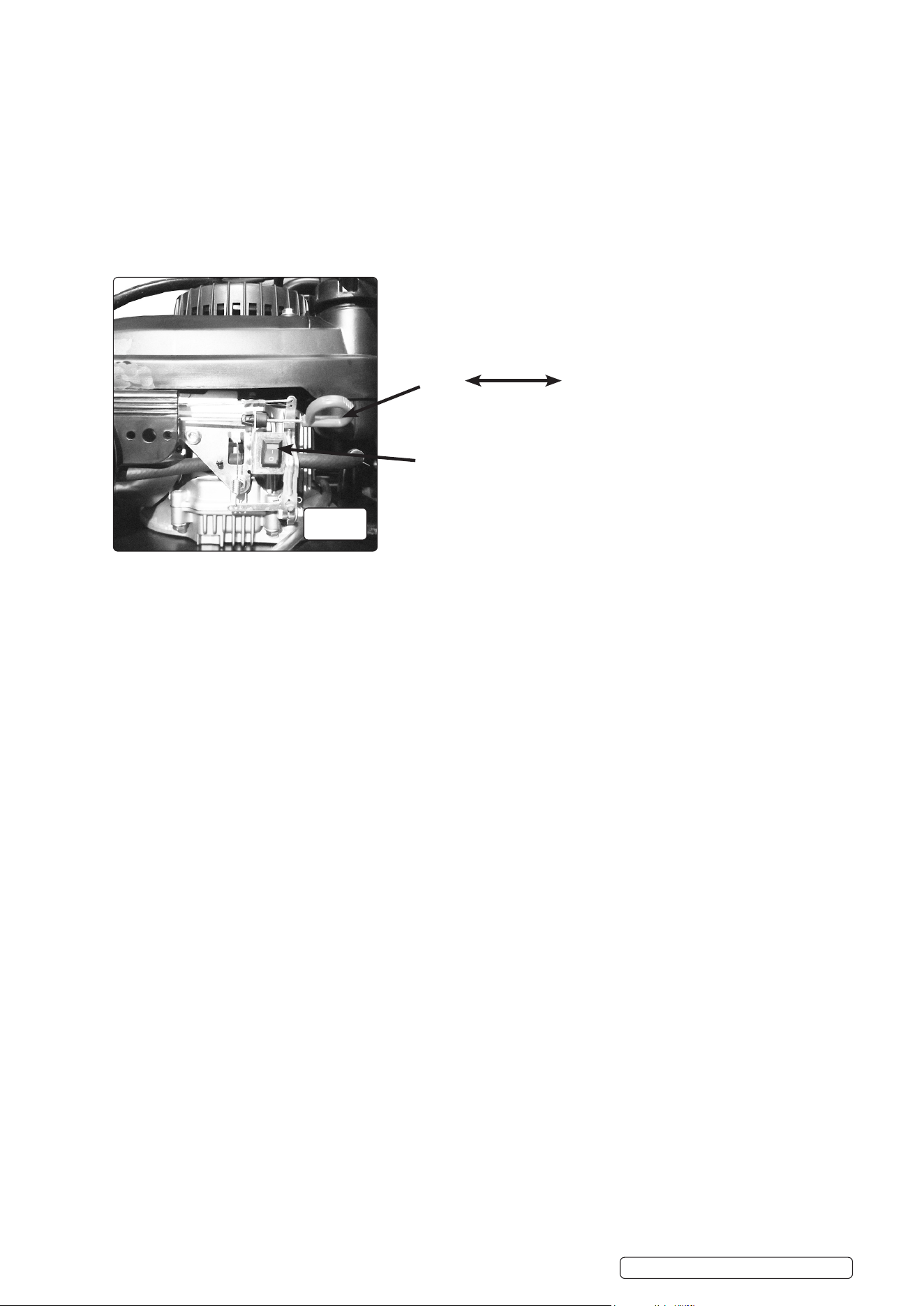
5.1.5. Switch the engine switch to the ON position ( press switch to “ I “ symbol). See fig.7.
5.1.6. If starting the engine from cold move the choke lever fully to the right. See fig.7.
5.1.7. To start the engine give a steady pull on the starting handle. The engine will be a little easier to start if the trigger is pressed during
starting. This must be done by a second person who can control the initial kickback as the water is expelled.
5.1.8. As the engine warms up move the choke lever left into the ‘run’ position.
5.2. NOZZLE SPRAY ADJUSTING g.4.
5.2.1. Adjust the nozzle pressure and spray pattern as described in section 4.3.
WARNING!
a) Avoid sudden bursts of water as this will cause the water pressure to drop and put extreme pressure on the hoses and
connections.
b) If another person is using water from the same supply as the washer, the water pressure will drop and the washer will not operate
correctly. Switch the engine off immediately and wait until the pressure is restored.
5.3. SHUT DOWN PROCEDURE
5.3.1. Turn the engine switch to the OFF position.
5.3.2. In an emergency turn the engine switch to the OFF position.
WARNING! De-pressurise after cleaning is completed, turn o the water supply and pull the trigger to de-pressurise the unit. Failure
to do so might result in personal injury due to discharge of high-pressure water.
5.4. CLEANING WITH DETERGENTS
IMPORTANT This pressure washer is intended for use with special pressure washer detergents only. DO NOT use powdered soaps,
as this will clog the injection system. Follow the detergent manufacturer’s directions.
IMPORTANT Working with a detergent ensures quick soaking of the dirt, and allows the high-pressure water to penetrate and remove
the dirt more effectively. Always spray detergent on a dry surface, DO NOT pre soak the area. Soaking the surface dilutes the
detergent and reduces its cleaning ability.
WARNING! Damage may occur to surfaces if chemicals (detergents) are allowed to dry on them. Wash and rinse a small section at a
time. Avoid working on hot surfaces or under direct sunlight.
5.4.1. When applying detergents, always operate the unit at low water pressure position (fig.2). This provides a gentle application of the
detergent, with the water pressure equivalent to a garden hose. Always test the detergent in a concealed area before use.
5.4.2. The liquid detergent will be mixed with water automatically, and discharged through the detergent nozzle at a low pressure.
5.4.3. Allow detergent to remain on the surface for a short time before rinsing. DO NOT allow detergent to dry on the surface.
5.5. SHUTTING DOWN AND CLEANING UP
5.5.1. Skip step 5.5.2 if you are not using detergent.
5.5.2. After cleaning with detergent, fill the detergent tank with clean water. Spray water at a low pressure for one minute, so that all detergent
is flushed out of the system.
5.5.3. Stop the engine (→ Section 5.3 Shut Down Procedure).
5.5.4. Turn off the water supply and disconnect the water supply from the water inlet.
5.5.5. Point spray gun in safe direction, push trigger lock, and squeeze spray gun trigger to relieve retained high water pressure. Engage the
trigger safety lock (fig.3) on the spray gun.
5.5.6. Disconnect the garden hose from the pump.
5.5.7. Disconnect the pressure hose from the pump and pressure gun for storage. For long-term storage instructions, see section 7.8.
5.5.8. Rewind the pressure hose and attach it to the hose hook.
5.5.9. Disconnect the gun and wand, then insert them into the upper gun holder.
5.5.10. Fold the handle and store.
NOTE: After turning off the machine, wait for 20 minutes to prevent plastic parts from being burned by muffler, then fold the handle.
5.6. ADDING/CHECKING OIL
IMPORTANT Oil has been drained for shipping. Failure to fill engine with oil before starting engine will result in permanent damage and
will void engine warranty.
WARNING! Always check the oil level before starting the engine, making sure the pressure washer is on a level surface.
NOTE: When adding oil, use oil funnel. The dip stick is marked L (Low), H (High).
Original Language Version
© Jack Sealey Limited
Choke lever
Open Close
Engine On/O switch
fig.7
PWM1300.V2 Issue 2 (2) 07/12/20

5.6.1. Remove oil tank dipstick (fig.1.12) and wipe it with a clean cloth.
5.6.2. Replace and re-tighten the dipstick.
5.6.3. Remove the dipstick again and check the oil level. It should be at the top of the full (H) indicator on the dipstick.
5.6.4. If low, add oil slowly into the oil tank. DO NOT overfill. After adding oil, wait one minute and then recheck the oil level.
5.6.5. Replace and re-tighten the dipstick.
5.7. ADDING FUEL
9 Fill the fuel tank outdoors or in well-ventilated areas.
9 Make sure there is enough fuel in the fuel tank before operating the pressure washer.
9 Use only clean, fresh, unleaded fuel. Use a minimum of 87octane/87 AKI (91 RON).
9 Keep fuel away from sparks, open ames, pilot lights, heat, and other ignition sources.
9 Check fuel hoses, tank, caps, and ttings frequently for cracks or leaks. Replace if necessary.
9 If fuel spills, wait until it evaporates before starting engine.
8 DO NOT use old petrol, and DO NOT mix oil with petrol.
5.7.1. Stop the engine (Section 5.3 Shut Down Procedure) and let it cool at least two minutes before removing the fuel tank cap (fig.1.5).
5.7.2. Clean the fuel cap area of dirt and debris. Remove the fuel tank cap and make sure the fuel lter is in place.
5.7.3. Fill the fuel tank (fig.1.15) with fuel. Never overll the fuel tank. Fill tank to no more than ½″ (13 mm) below the bottom of the ller neck
to provide space for expansion caused by the engine heat.
5.7.4. Replace the fuel tank cap.
6. MAINTENANCE - WASHER
WARNING! Maintenance should only be performed with the engine turned off, the spark plug cap removed and the unit disconnected
from the mains water supply.
6.1. WINTER STORAGE
6.1.1. Fill the pump with an antifreeze mixture before storing in a frost free, safe, dry area for the winter. Introduce the antifreeze by the following
method.
1. Shut off the water supply and disconnect the supply hose. Relieve pressure within the pump by squeezing the gun trigger. Remove the
high pressure hose and let all water drain from it. Hold gun/lance with nozzle downwards and pull trigger until all water has drained out.
2. Disconnect the ignition lead from the spark plug.
3. Connect a short length of garden hose to the water inlet and using a funnel pour an antifreeze mixture into it.
4. Pull the recoil starter several times to circulate the antifreeze through the pump. Continue to add antifreeze and pull the recoil until
antifreeze is expelled from the pump.
6.2. CLEANING WATER INLET FILTER
WARNING! DO NOT operate this pressure washer without the water inlet lter in place, as deposits could build up internally and
aect the functioning of the unit.
6.2.1. This pressure washer is equipped with a water inlet lter.
6.2.2. The water inlet lter must be kept clean at all times, otherwise it can restrict the water ow to the pump unit and damage it.
6.2.3. Remove the quick-connect coupler from the water inlet, then carefully remove and clean the water inlet lter.
7. MAINTENANCE - ENGINE
7.1. Change engine oil after the first 8 hours of operation. Thereafter, change oil monthly or every 50 hours of operation. Change oil more
often if engine is operated under heavy load, or in high ambient air temperatures. During normal operation, partially burned fuel, small
particles of metal from the cylinder walls, pistons, bearings and combustion deposits will gradually contaminate the oil. If the oil is not
changed regularly, these foreign particles can cause increased friction and a grinding action which shortens the life of the engine. Fresh
oil also assists in cooling. Old oil gradually becomes thick and loses its cooling ability as well as its lubricating qualities.
7.2. CHECKING THE OIL LEVEL. Ensure the unit is on a level surface.
7.2.1. Unscrew the dipstick (fig.5) and wipe it clean of oil. Note that the maximum oil level should be just below the opening of the filler neck.
7.2.2. Check the oil level by seating the dipstick into the hole without screwing it in. If there is no oil on the dipstick when it is removed the level
is too low and should be topped up immediately with an SAE10W - 30 oil.
7.2.3. Top up oil if necessary and recheck level.
7.2.4. Screw dipstick fully home to seal oil fill hole.
7.3. DRAINING ENGINE OIL
7.3.1. The engine oil should be replaced after the first 20 hours of operation, or after the first month of use. After that, it should be replaced
every 100 hours or every six months.
7.3.2. To drain the engine oil:
1. Loosen the oil tank dipstick (fig.1.12).
2. Place an oil container underneath the opening at the base of the filler tube.
3. Remove the hex screw plug from the oil drain (fig.5) and drain the oil into the container.
4. Once the oil has been completely drained, replace the hex screw (fig.5) and oil tank dipstick.
7.4. CHECKING AIR FILTER
IMPORTANT: Clean air filter (fig.1.8) element after every 50 hours of use (every 10 hours under dusty conditions).
7.4.1. To access the air filter element rotate cover (fig.1.8) anti-clockwise and remove the foam filter from the air intake base moulding.
7.4.2. Wash the foam element with a household detergent or a high flash-point solvent and squeeze dry. When the element is thoroughly dry soak
it in clean engine oil. Squeeze out any excess oil, fit back over the air intake base moulding, locate and replace cover.
7.4.3. The foam element should be replaced after every 300 hours of service.
7.5. INSPECTING, REPLACING OR CLEANING THE SPARK PLUG
NOTE: The spark plug should be checked after every 100 hours of operation or every six months.
7.5.1. To replace or clean the spark plug:
1. Disconnect the spark plug wire by pulling it off the spark plug.
2. Using provided spark plug wrench, remove the spark plug by turning it counter-clockwise. If there is a carbon sediment build-up,
remove it. If there is too much carbon sediment, replace the spark plug.
3. Check the gap with a wire gauge. If necessary, reset the gap to 0.7-0.8 mm. Install and tighten the spark plug to the recommended
torque – 180 lb/in (20 Nm).
4. Reinstall the spark plug wire and protection cage in reverse order.
Original Language Version
© Jack Sealey Limited
PWM1300.V2 Issue 2 (2) 07/12/20
NOTE: In some areas, local law requires using a resistor spark plug to
suppress ignition signals. If this engine was originally equipped with a
resistor spark plug, use the same type for replacement.
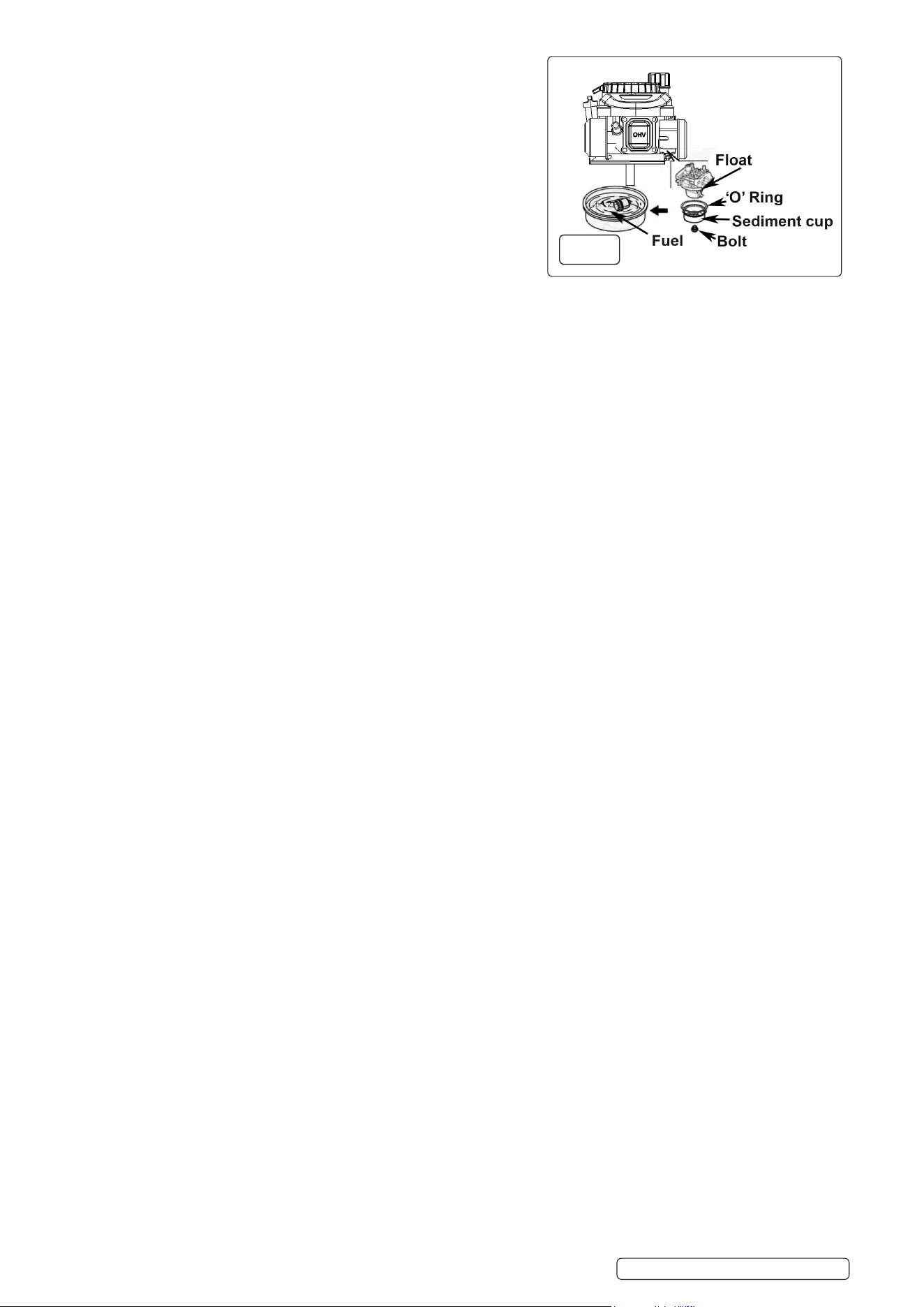
7.6. CLEANING THE CARBURETTOR
7.6.1. To clean the carburettor (fig.8):
1. Unscrew the bolt on the bottom of carburettor.
2. Push the float up four to five times, then clean sediment cup with fuel.
NOTE: Ensure you replace the O ring when putting the sediment cup back.
7.7. WINTER AND LONG TERM PUMP STORAGE
7.7.1. STEP 1: ENGINE STORAGE. If the unit is not to be used for more than
one month the following procedure should be followed.
1. Top-up engine oil to maximum.
2. Drain petrol from the fuel tank, fuel line, fuel tap and carburettor.
3. Pour one teaspoon of engine oil through the spark plug hole, pull the recoil
starter several times and replace the spark plug. Then pull the starter slowly until an increase in pressure is felt indicating that the piston has
commenced its compression stroke and leave it in this position. This closes both the intake and exhaust valves and prevents the inside of the
cylinder from rusting.
7.7.2. STEP 2: PROTECT FUEL SYSTEM
WARNING! Petrol is extremely ammable and potentially explosive. DO NOT perform maintenance on petrol associated components
where there is any source of ignition present such as cigarettes, sparks, naked ame or hot surfaces.
FUEL ADDITIVE:
Fuel can become stale when stored for over 30 days. Stale fuel causes acid and gum deposits to form in the fuel system or on essential
carburettor parts. Please use fuel stabilizer to keep fuel fresh. Run the engine for 2 minutes to circulate the stabilizer throughout the fuel
system before storage.
DRAIN FUEL
If fuel in the engine has not been treated with a fuel stabilizer, it must be drained into an approved container. Run the engine until it
stops from lack of fuel. Remove the hex screw from the carburettor (fig.8) then drain the fuel from the tank, carburettor, and tube. Screw
the carburettor drain hex screw back once the fuel has been completely drained.
7.7.3. STEP 3: CHANGE OIL (See sections 7.1 - 7.4)
7.7.4. While engine is still warm, drain oil from crankcase. Remove the hex screw from the crankcase (fig.5). Drain the oil to a container. Refill
with recommended grade oil (SAE 10W-30).
IMPORTANT:
• If the pressure washer is to be stored with fuel in the fuel tank and carburettor, it is important to reduce the hazard of fuel vapour ignition.
• Select a well-ventilated storage area away from any appliance that operates with a flame, such as a furnace, water heater, or clothes
dryer. Also avoid any area with a spark-producing electric motor, or where power tools are operated.
• If possible, avoid storage areas with high humidity, this will promote rust and corrosion.
• Place the pressure washer on a level surface. Tilting can cause fuel or oil leakage.
7.8. MAINTENANCE SCHEDULE.
7.8.1. Before each use;
Check engine oil level.
Inspect the unit for evidence of oil and fuel leaks.
7.8.2. After the first 8 hours or 20 hours only;
Change the engine oil.
Check pump oil
Every 50 hours.
Change the engine oil.
7.8.3. Every 6 months or 100 hours;
Change the engine oil.
Check pump oil
Inspect and clean air filter.
Clean the deposit cup.
Clean spark plug and check gap.
7.8.4. Every 300 hours;
Replace air cleaner element.
Check valve clearances.
Check idling speed.
Clean spark plug and check gap.
Clean fuel tank fuel filter..X, fig.Y)
Original Language Version
© Jack Sealey Limited
fig.8
PWM1300.V2 Issue 2 (2) 07/12/20
Original Language Version
© Jack Sealey Limited
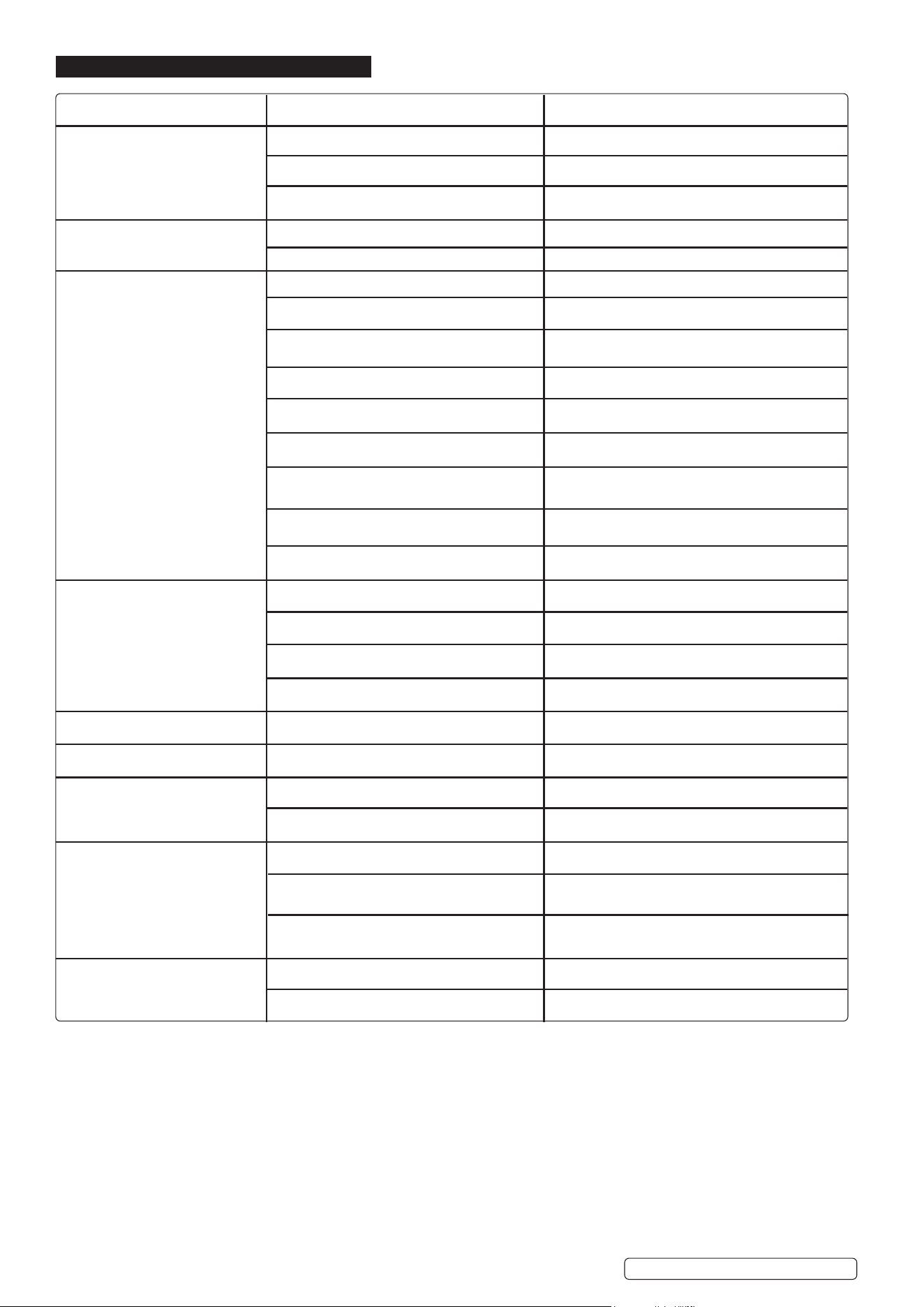
PROBLEM POSSIBLE CAUSES REMEDY
Engine will not start Is engine oil level correct Top-up oil to correct level
Engine switch not in the ON position Turn switch ON
Pressure build-up in pump Operate trigger
Engine is overloaded Nozzle partially blocked Clean nozzle
Excessive pressure build-up Return to dealer to have reflux valve adjusted.
Engine running but pump not Mains water turned off Turn on mains water
building maximum pressure or has
irregular pressure Unit has been stored in freezing temperatures Thaw out completely including hose, gun and wand.
Inadequate water supply Minimum required is 6L/min at 2 bar.
Water inlet filter clogged Clean filter
Kink in water supply hose Straighten hose
Wand nozzle worn or damaged Replace nozzle
Air in pump Run unit with gun open and wand removed until air
is purged
Suction or discharge valve clogged or worn out Clean suction or discharge valves
Bypass valve not operating effectively Clean bypass valve
No intake of chemicals Injection tube not properly attached to unit Push tube firmly onto siphon nozzle
Tube cracked or split Replace tubing
Nozzle set to high pressure Move nozzle to low pressure position
Siphon nozzle blocked Clean nozzle
Trigger will not move Trigger lock engaged Release trigger lock
Water in crankcase High humidity Change oil more frequently
Noisy operation Worn seals Return to Sealey stockist for seal replacement
Worn bearings Return to Sealey stockist for bearing replacement
Rough/pulsating operation with Air mixed with water Check inlet line for correct size or restriction
pressure drop
Inlet restriction Check for incorrectly sized plumbing, air leaks, or
blockages
Air mixed with water Check inlet line for correct size or restriction
High crankcase temperature Wrong grade of oil Use recommended oil
Oil too high/low Adjust oil level to recommended.
8. TROUBLESHOOTING
PWM1300.V2 Issue 2 (2) 07/12/20
Sealey Group, Kempson Way, Suffolk Business Park, Bury St Edmunds, Suffolk. IP32 7AR
01284 757500 01284 703534 sales@sealey.co.uk www.sealey.co.uk
ENVIRONMENT PROTECTION
Recycle unwanted materials instead of disposing of them as waste. All tools, accessories and packaging should be sorted, taken to
a recycling centre and disposed of in a manner which is compatible with the environment. When the product becomes completely
unserviceable and requires disposal, drain any fluids (if applicable) into approved containers and dispose of the product and fluids
according to local regulations.
Note: It is our policy to continually improve products and as such we reserve the right to alter data, specifications and component parts without prior
notice. Please note that other versions of this product are available. If you require documentation for alternative versions, please email or call
our technical team on technical@sealey.co.uk or 01284 757505.
Important: No Liability is accepted for incorrect use of this product.
Warranty: Guarantee is 12 months from purchase date, proof of which is required for any claim.
WEEE REGULATIONS
Dispose of this product at the end of its working life in compliance with the EU Directive on Waste Electrical and Electronic Equipment
(WEEE). When the product is no longer required, it must be disposed of in an environmentally protective way. Contact your local solid
waste authority for recycling information.
Original Language Version
© Jack Sealey Limited
PWM1300.V2 Issue 2 (2) 07/12/20
