1. SAFETY
9 Ensure that Health & Safety, local authority and general workshop practice regulations are strictly adhered to when using tools.
9 Maintain the equipment in good and clean condition for best and safest performance. DO NOT use if damaged.
9 If required, ensure that the vehicle to be worked on is adequately supported with axle stands, ramps and chocks.
WARNING! Select neutral (or ‘park’ if automatic transmission) and keep hands clear of the engine as engine rotation may occur
when using this tool. The ignition MUST BE turned off.
WARNING! Turn regulator knob fully anti-clockwise before connecting to compressed air.
9 Excess pressure will damage the gauge and will invalidate the warranty.
9 Wear approved eye protection. A full range of personal safety equipment is available from your Sealey stockist.
9 Wear suitable clothing to avoid snagging. Do not wear jewellery and tie back long hair.
9 Account for all tools and parts being used and do not leave them in, on or near the engine.
▲ IMPORTANT: Refer to the vehicle manufacturer’s service instructions, or proprietary manual, to establish the current procedure and
data. These instructions are provided as a guide only.
2. INTRODUCTION
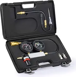
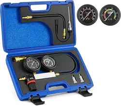
Designed to detect a variety of common engine faults including; worn piston rings, worn valves, cylinder head cracks and blown head gaskets. Twin
gauge manifold shows percentage of cylinder leakage and cylinder pressure. Supplied in storage case with instructions. For spark plugs fitted into a
deep recess, VS200/A, Long Reach Compression Tester Adaptor may be required.
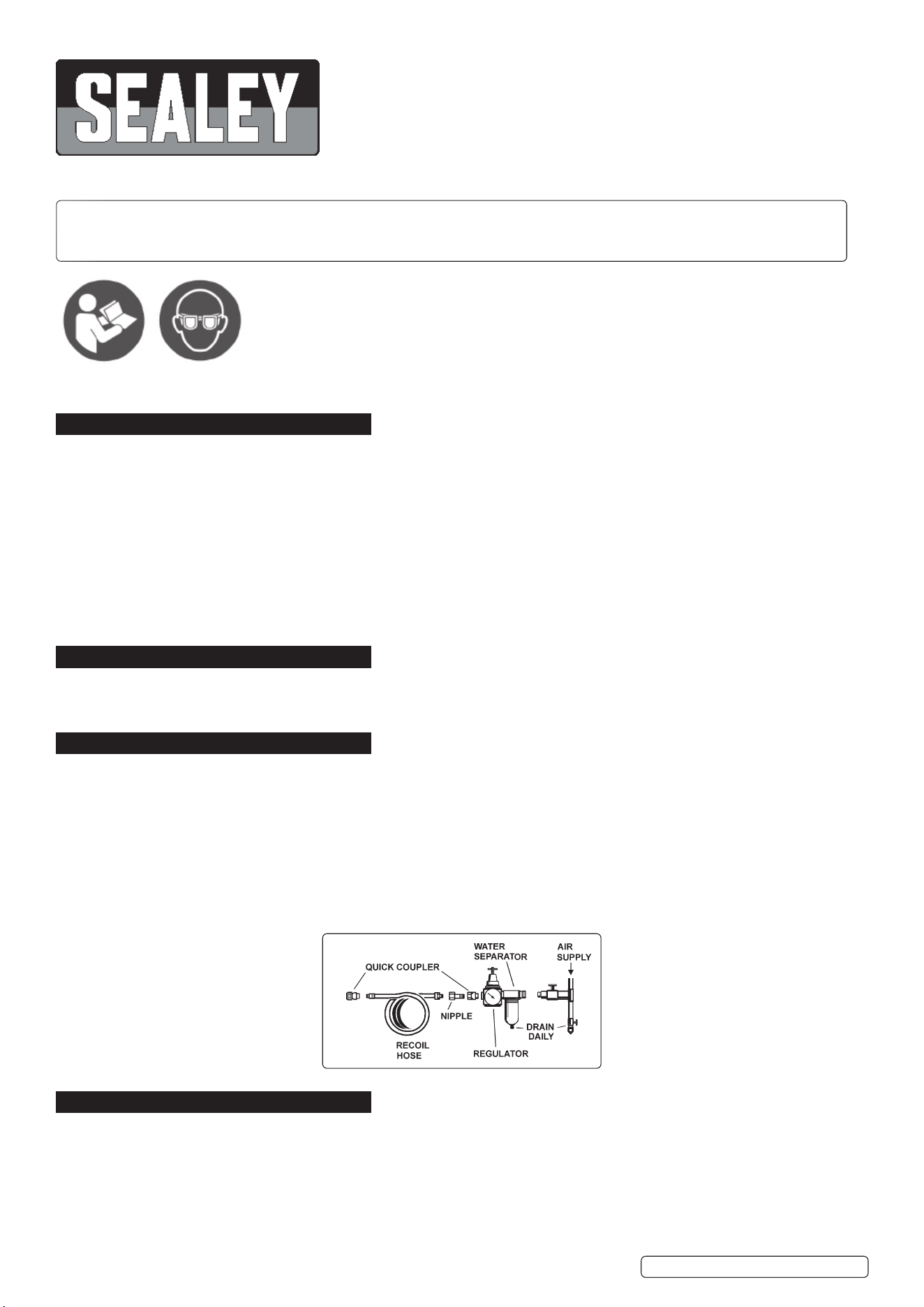
3. AIR SUPPLY
The recommended hook-up is shown below.
3.1. Ensure that the air valve regulator is in the “off” position before connecting to the air supply.
3.2. You will require an air pressure of 45 to 100psi.
WARNING! Ensure the air supply is clean and does not exceed the pressure quoted. Too high an air pressure and/or unclean air
will shorten the life of the tester due to excessive wear and may be dangerous, causing damage and/or personal injury.
3.3. Drain the compressor air tank daily. Water in the air line will damage the tester.
3.4. Clean compressor air inlet filter weekly.
3.5. Line pressure should be increased to compensate for unusually long air hoses (over 8 metres). The minimum bore for hose and
fittings is 1/4”.
3.6. Keep hoses away from heat, oil and sharp edges. Check hoses for wear and make certain that all connections are secure.
4. iOPERATION
OVERVIEW. Once the leakage tester has been connected to one of the cylinders compressed air is fed into that particular cylinder
through the built in pressure regulator. Diagnosis is made by observing the amount of leakage that is indicated on the cylinder leakage
gauge and by listening for leakage at various points of the cars system.
4.1. Location of listening points
4.1.1. OIL DIPSTICK TUBE - for leakage from damaged or worn rings and/or cylinder wall.
4.1.2. RADIATOR FILLER - for cylinder wall cracks or head gasket leakage.
4.1.3. ADJACENT CYLINDER - for head gasket leakage.
4.1.4. TAIL PIPE - for exhaust valve leakage.
VSE2020.V3 Issue 2 (2) 29/03/23
Original Language Version
© Jack Sealey Limited
CYLINDER LEAKAGE TESTER 2 - GAUGE
MODEL NO: VSE2020.V3
Thank you for purchasing a Sealey product. Manufactured to a high standard, this product will, if used according to these
instructions, and properly maintained, give you years of trouble free performance.
IMPORTANT: PLEASE READ THESE INSTRUCTIONS CAREFULLY. NOTE THE SAFE OPERATIONAL REQUIREMENTS, WARNINGS & CAUTIONS. USE
THE PRODUCT CORRECTLY AND WITH CARE FOR THE PURPOSE FOR WHICH IT IS INTENDED. FAILURE TO DO SO MAY CAUSE DAMAGE AND/OR
PERSONAL INJURY AND WILL INVALIDATE THE WARRANTY. KEEP THESE INSTRUCTIONS SAFE FOR FUTURE USE.
Refer to
Instructions
Wear Eye
Protection
4.1.5. CARBURETTOR AIR INLET - for inlet valve leakage.
4.1.6. FUEL INJECTION THROTTLE BODY - for inlet valve leakage.
4.2. Connecting the system
4.2.1. Run the engine until it reaches operating temperature.
4.2.2. Remove spark plugs, oil dipstick, radiator cap, air filter from carburettor or, if fuel injected, remove air filter or hose from the
throttle body.
4.2.3. Position No.1 piston at TDC on the compression stroke so that both inlet and exhaust valves are closed. Note: Always rotate the
engine in the normal operating direction. To position the piston correctly use a piston position gauge and remove the cam/rocker
cover so that closed valves can be confirmed.
4.2.4. Screw the cylinder hose (see ‘C’ in parts diagram) into the spark plug hole. If connecting to a 10 or 12mm thread, use adaptors 9 or 10
as appropriate. Do not connect to the tester until the leakage gauge (6) has been calibrated.
4.2.5. Screw a 1/4”BSPT male air line connector fitting into the threaded hole on the side of the regulator (connector not supplied).
Turn the regulator knob on the tester fully anti-clockwise to shut down the regulator before connecting the air. Connect the
compressed air, which must be between 45 and 100psi, to the regulator.
4.2.6. Calibrate the leakage gauge by turning the regulator knob clockwise until the needle on the right hand gauge reaches zero at the end
of the yellow ‘SET’ band. (Typically, this will happen between 15 to 20psi). Now insert connector ‘A’ on the cylinder hose into connector
‘B’ on the tester hose. Any leakage present in the currently connected cylinder will show on the cylinder leakage gauge as a percentage
loss. A cylinder that is not leaking will read approximately 20% in the green band.
4.2.7. Test all other cylinders, each at TDC, and compare the leakage figures to determine which cylinders are faulty.
4.2.8. If necessary, retest the cylinder(s) showing high leakage. Check the listening points (see 4.1) to determine the cause of the leakage.
4.3. Helpful Suggestions.
4.3.1. If 90-100% of excessive leakage shows on gauge the cylinder may not be at TDC on the compression stroke. Check to ensure that
the valves are closed. Always try to position piston at TDC for uniform results. It is unlikely that the gauge will read 100% leakage on
the gauge due to the internal bore of the flexible hose which will restrict air flow slightly.
4.3.2. If rings are broken or cylinder walls are scored excessive leakage will be identified.
4.3.3. It is important that all cylinders have reasonably uniform readings (as in compression testing). Differences in excess of 15% indicate
excessive leakage.
4.3.4. Large engines tend to leak more than small engines.
4.3.5. If leak is excessive on a vehicle with low mileage, piston rings may be stuck. Treat engine with quality tune-up oil for a period of time
and then re-test before disassembling.
4.3.6. The lower the pitch of the leakage sound, the greater the leak.
4.3.7. To assist with listening use a length of clean hose, or a mechanic’s stethoscope with the probe removed.
4.3.8. When making repeat tests on the same cylinder, variations in the piston position and engine temperature can cause gauge
readings to differ by up to 10%.
4.3.9. If an engine has multiple faults (such as worn rings and burned valves), the tester may indicate only the most serious fault.
Note: There is always some leakage past the piston rings. As a result you will always hear some leakage when listening to the dipstick
tube.
ITEM PART NO: DESCRIPTION
2 VSE2020.V3-02 PRESSURE
REGULATING VALVE
3 VSE2020.V3-03 VALVE
4 VSE2020.V3-04 HOSE
5 VSE2020.V3-05 PRESSURE GAUGE
6 VSE2020.V3-06 PRESSURE GAUGE
7 VSE2020.V3-07 CONNECTOR
(FEMALE)
8 VSE2020.V3-08 HOSE WITH
CONNECTOR
9 VSE2020.V3-09 CONNECTOR
10 VSE2020.V3-010 CONNECTOR
11 VSE2020.V3-011 O-RING
Original Language Version
© Jack Sealey Limited
VSE2020.V3 Issue 2 (2) 29/03/23
Sealey Group, Kempson Way, Suffolk Business Park, Bury St Edmunds, Suffolk. IP32 7AR
01284 757500 sales@sealey.co.uk www.sealey.co.uk
ENVIRONMENT PROTECTION
Recycle unwanted materials instead of disposing of them as waste. All tools, accessories and packaging should be sorted,
taken to a recycling centre and disposed of in a manner which is compatible with the environment. When the product
becomes completely unserviceable and requires disposal, drain any fluids (if applicable) into approved containers and
dispose of the product and fluids according to local regulations.
Note: It is our policy to continually improve products and as such we reserve the right to alter data, specifications and component parts without prior
notice. Please note that other versions of this product are available. If you require documentation for alternative versions, please email or call
our technical team on technical@sealey.co.uk or 01284 757505.
Important: No Liability is accepted for incorrect use of this product.
Warranty: Guarantee is 12 months from purchase date, proof of which is required for any claim.
REGISTER YOUR
PURCHASE HERE