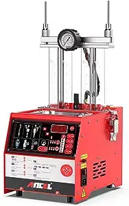
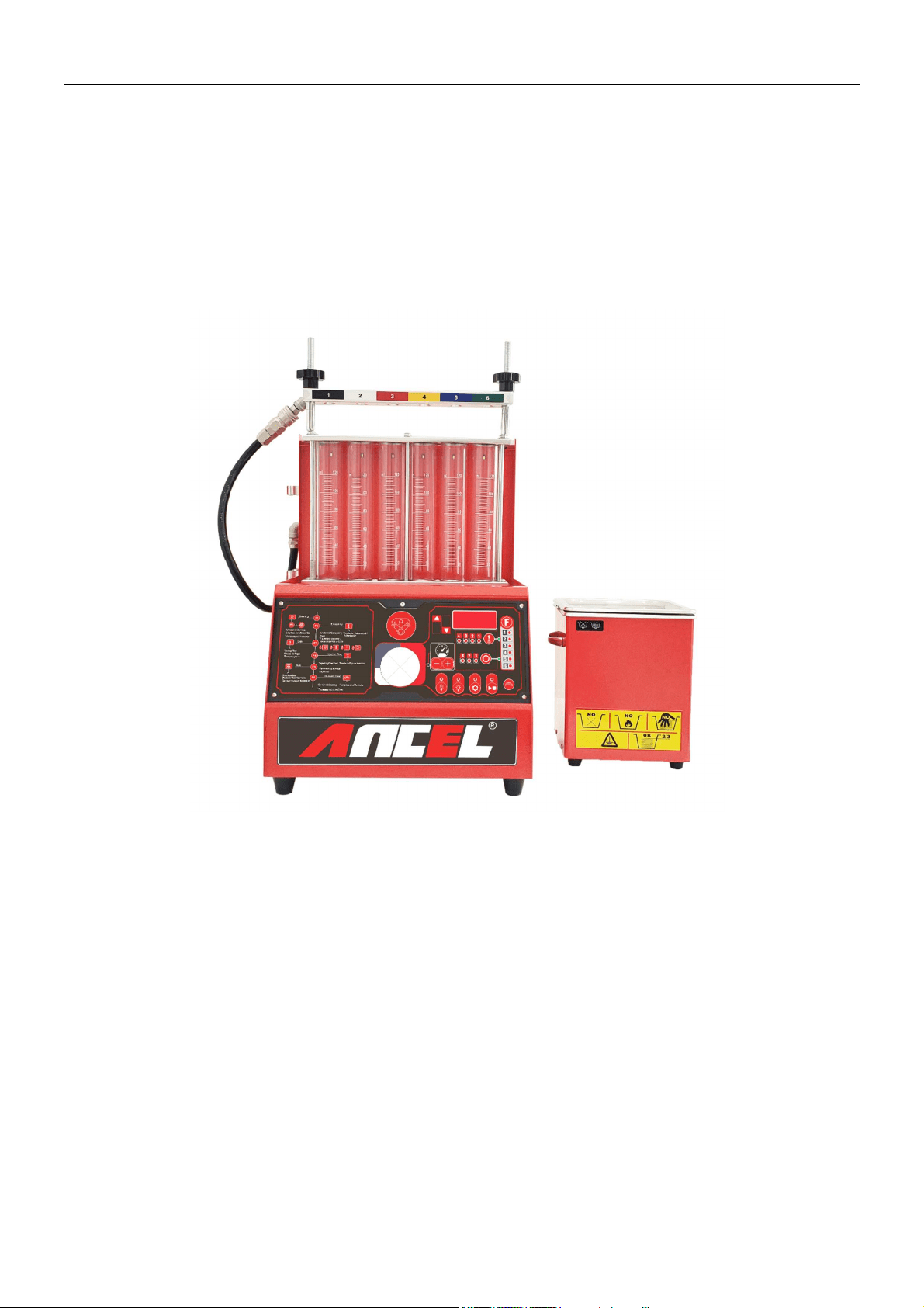
AJ600
Injector Cleaner & Tester
ANCEL
AJ600 Injector Cleaner & Tester
AJ600
Injector Cleaner & Tester
ANCEL
General Notice & Disclaimer
All rights reserved! Any company or individual person shall not copy or backup this user manual in any format
(electronic, mechanical, photocopying, recording or other formats) without written permission from us. The manual is
for the use of the products manufactured by our company, which shall not assume any responsibility for the
consequences arising from the use of it to guide the operations of other equipment.
The device is intended for the use of professional technicians or maintenance and repair personnel.
We assumes no responsibility for device damages or problems resulted from the usage of other parts or consumables,
rather than original products of us or products approved by the company.
Important Safety Instructions
• Please read this manual carefully before using the equipment.
• Be careful when touching high temperature parts of the equipment or engine.
• Please do NOT touch hot parts or rotating fan blades.
• If use a low-quality power cord, it may cause overheating.
• The device should be cooled completely before storage and the line should be wound up.
• The cleaning agent for the device is a flammable and weakly volatile liquid. Smoking and lighting fires are strictly
prohibited during the cleaning process.
• The instrument should be placed in a room that is not exposed to direct sunlight and is well ventilated, and signs
“Smoking and lighting fires strictly forbidden” and “Danger warning of inflammables” should be posted.
• The operator’s hair, clothes, fingers and other parts of the body should be kept away from the operating parts of
the equipment.
• To prevent electric shocks, do you touch the operating equipment in wet areas or operate it in the rain.
• Please operate the device as described in the manual. Use accessories recommended by the manufacturer.
• It is strictly forbidden to open the ultrasonic system under the circumstances that ultrasonic cleaning agent has not
been added into the ultrasonic cleaning pool. Otherwise, the ultrasonic equipment may be damaged easily.
• The housing of the device must be reliable and grounded.
• Automobile exhaust contains a variety of toxic and harmful gases (such as carbon monoxide, hydrocarbon, nitrogen
oxide and etc.). During the test, the exhaust should be directed outdoors and the room should be well ventilated.
• The temperature of the exhaust pipe and water tank of the automobile’s engine is high. Do not touch them to
prevent burns.
• Please pull up the handbrake of the vehicle to be cleaned, shift the transmission to neutral position and block the
front wheel before free disassembly cleaning.
• Wear safety glasses when operating. Daily wear glasses are not safety glasses.
• When disconnecting a pressurized fuel pipe union, please cover the union with a towel to avoid getting hurt by
fuel gushing out and causing fires.
• Test solution is used by the main unit of the device uses, and ultrasonic cleaning agent is used for ultrasonic
cleaning.
: INDICATES WHERE ATTENTION SHOULD BE PAID WHEN OPERATING THE DEVICE.
: indicates the possibility of product damage and personnel injury during operating.

AJ600
Injector Cleaner & Tester
ANCEL
Content
I. INTRODUCTION TO INJECTOR CLEANER & TESTER .................................................................................................. 1
1.1
B
RIEF
I
NTRODUCTION
............................................................................................................................................................ 1
1.2
F
UNCTIONS AND
F
EATURES
................................................................................................................................................... 1
1.3
W
ORKING CONDITIONS
&
S
PECIFICATIONS
............................................................................................................................ 2
II. STRUCTURE OF INJECTOR CLEANER & TESTER ........................................................................................................ 3
2.1
O
VERVIEW
............................................................................................................................................................................. 3
2.2
C
ONTROL
P
ANEL
.................................................................................................................................................................... 3
III. INSTALLATION ................................................................................................................................................................... 4
3.1
I
NSTALLATION OF TOP
-
SUPPLY INJECTORS
(EFI/MPI/SFI) .................................................................................................. 4
3.2
I
NSTALLATION OF SIDE
-
SUPPLY INJECTORS
............................................................................................................................ 5
IV. OPERATING PROCEDURES .............................................................................................................................................. 5
4.1
P
REPARATION
........................................................................................................................................................................ 5
4.2
C
LEANING
&
TESTING SEQUENCES
......................................................................................................................................... 5
4.3
P
ROCEDURE AFTER WORK OPERATION
................................................................................................................................... 5
V. OPERATION ........................................................................................................................................................................... 6
5.1
R
ESISTANCE
T
EST
.................................................................................................................................................................. 6
5.2
U
LTRASONIC
C
LEANING
........................................................................................................................................................ 6
5.3
U
NIFORMITY
/S
PRAYABILITY
T
EST
......................................................................................................................................... 6
5.4
L
EAKAGE
T
EST
...................................................................................................................................................................... 7
5.5
I
NJECTING
F
LOW
T
EST
........................................................................................................................................................... 7
5.6
A
UTO
.
T
EST
........................................................................................................................................................................... 8
5.7
O
N
-V
EHICLE
C
LEANING
........................................................................................................................................................ 9
VI. TRANSPORTING AND STORING .................................................................................................................................... 10
6.1
T
RANSPORTING
.................................................................................................................................................................... 10
6.2
S
TORING
.............................................................................................................................................................................. 10
6.3
I
NSTALLATION
E
NVIRONMENT
............................................................................................................................................. 10
VII. TROUBLESHOOTING & PRECAUTIONS ..................................................................................................................... 11
7.1
T
ROUBLESHOOTING
............................................................................................................................................................. 11
7.2
P
RECAUTIONS
...................................................................................................................................................................... 11

1
AJ600
Injector Cleaner & Tester
ANCEL
Special note: This user’s manual is an introduction to the structure, functions, operations, cautions, maintenance and
troubleshooting for the proper use of the equipment, we retain the right of changing product design and specifications,
the actual configuration according to the packing list.
I. Introduction to Injector Cleaner & Tester
Welcome to use Injector Cleaner & Tester equipment. It is a mechatronic product that combines ultrasonic cleaning
technology with microprocessor fuel pressure control cleaning and testing technology.
1.1 Brief Introduction
The User Manual is applicable to the serial Injector Cleaner & Tester equipment.
1.2 Functions and Features
Main functions
Ultrasonic cleaning:
To clean injectors to remove the carbon deposition on them completely.
Resistance test
To test the resistance of fuel injector
Uniformity / Sprayability test:
To test the uniformity of injecting amount of each injector, and to monitor the spraying status of each injector
with the help of backlight.
Leakage test:
To test the sealing and dribbling conditions of injectors under system pressure.
Injecting flow test:
To check the injecting amount of the injector in 15 seconds of constant injection.
Auto. test:
To test injectors by preset program conditions.
On-Vehicle Cleaning:
Coming with a variety of disassembly-free cleaning connectors, the device can be used to perform on-vehicle
cleaning and maintenance for various vehicle models.
Low resistance injectors test function
Through the dedicated motherboard, it supports the full and long test of low resistant fuel injector such as 1
ohm.
Multi items Setting:
Set different parameters of the device, including the buzzer sound level, display brightness, and backlight
brightness.
Version information:
to check the software version information of the current device.
Main Features
The special structure design makes the disassembly and assembly of the fuel separator easier and greatly
improves the work efficiency.
With the resistance test of the injectors one by one, get to know the condition of the injectors
With the dedicated motherboard, it can support the full and long test of low resistant fuel injector such as
1 ohm.
The unique fuel circuit depressurization technology can make the machine automatically depressurize in the
case of sudden shutdown, avoiding equipment damage or personal injury.
The back door of the cabinet opens or closes with one touch.
The brightness of the screen and backlight, and the level of the buzzer can be manually set and saved.
The machine has a strong ultrasonic cleaning ability, which can remove carbon deposits and impurities on the
fuel injection nozzle to the greatest extent.
The product adopts fuel pressure adjustment and control technology by microcomputer, which can ensure stable
fuel pressure and wide adjustable range. It is applicable to vehicles equipped with a variety of gasoline injection
systems. Meanwhile, the automation of injectors’ cleaning and testing processes can be realized.
Thanks to the adoption of microcomputer automatic control and digital display technologies, the cleaning and
testing processes can be controlled automatically and the parameters of the main status can be monitored in real
time.
Automatic fuel drain during a certain test can be realized via a routine, owing to the adoption of automatic fuel

2
AJ600
Injector Cleaner & Tester
ANCEL
drain control technology. Start or [Stop] fuel drainage via the [Drain] button on the control panel in running or
stop state..
Adopting humanization design can make the system pressure fast restored to the default values.
1.3 Working conditions & Specifications
Working conditions:
Temperature: -10~+40℃ Relative humidity: <85%
Intensity of outer magnetic field: <400A/m
No naked flame within 2m.
Specifications:
Main unit power supply:
AC220V±10% 50Hz/60Hz or AC110V±10% 60Hz
Input power: 230W
Ultrasonic cleaner power: 100W
Resistance test accuracy: 0.1
Ω
Simulated RPM range:100~9900rpm, step:10rpm
Time range: 5~300s, step:5s
Pulse width: 0.1~25ms,step: 0.1ms
Fuel tank capacity: 2000 ml
Work pressure: 0-7bar
3
AJ600
Injector Cleaner & Tester
ANCEL
II. Structure of Injector Cleaner & Tester
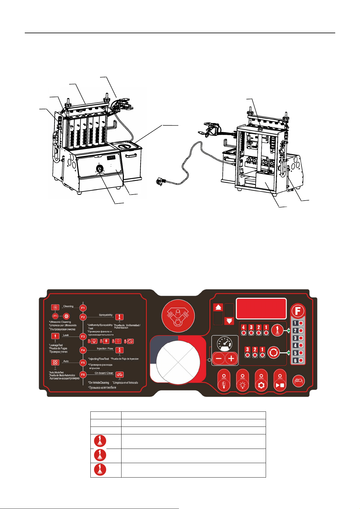
2.1 Overview
1-Pulse line; 2-Fuel separator assembly; 3-Observation window tube; 4-Control panel; 5- Fuel pressure gauge;
6-Fuel outlet hose; 7- Ultrasonic cleaner ;8-Test liquid addition port; 9-Fuel tank 10-Liquid level indicator tube
(test liquid drain tube)
• Attention: there may be slight difference between the illustrations in this manual and the actual product. Subject
to actual product.
2.2 Control Panel
Key Function Description [en, es, ru, pt]
F->1
Ultrasonic cleaning
F->2
Uniformity & Spray ability test
-
>1
RPM
-
>2
Pulse width
-
>3
Time
1
2
3
4
5
6
8
9
7
10
4
AJ600
Injector Cleaner & Tester
ANCEL
-
>4
No. / Mode
F->3
Leakage test
F->4
Injecting flow test
F->5
Automatic test
-
>1
Mode 1 (Acceleration test)
-
>2
Mode 2 (Deceleration test)
-
>3
Mode 3 (Acceleration+ Deceleration test)
F->6
On
-
Vehicle cleaning
Fuel pressure + / -
Resistance test
Backlight on / off
Setting
bp. 0-8: Buzzer sound level
dl. 1-7: Display brightness
bl. 0-15: Backlight brightness
sa.0/1: 0-Not save as default. 1- Save as default
Run / Stop
III. Installation
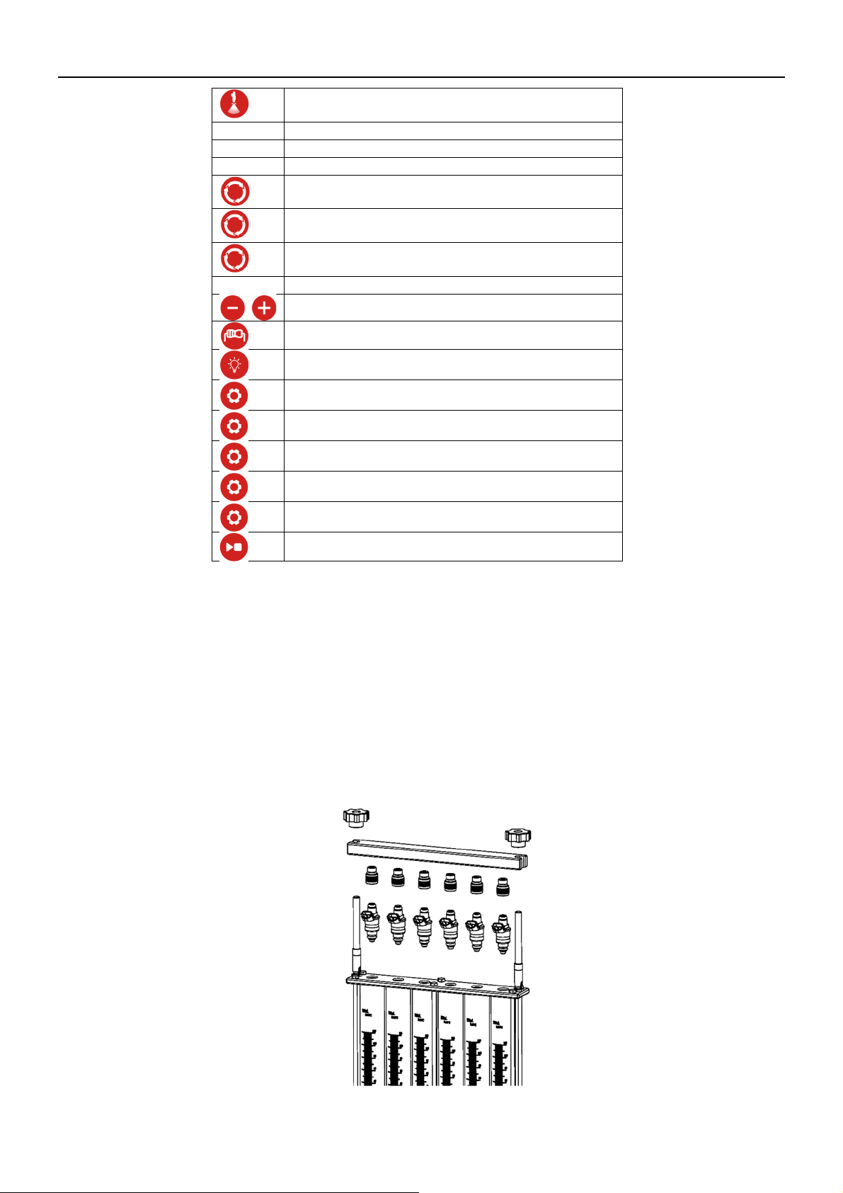
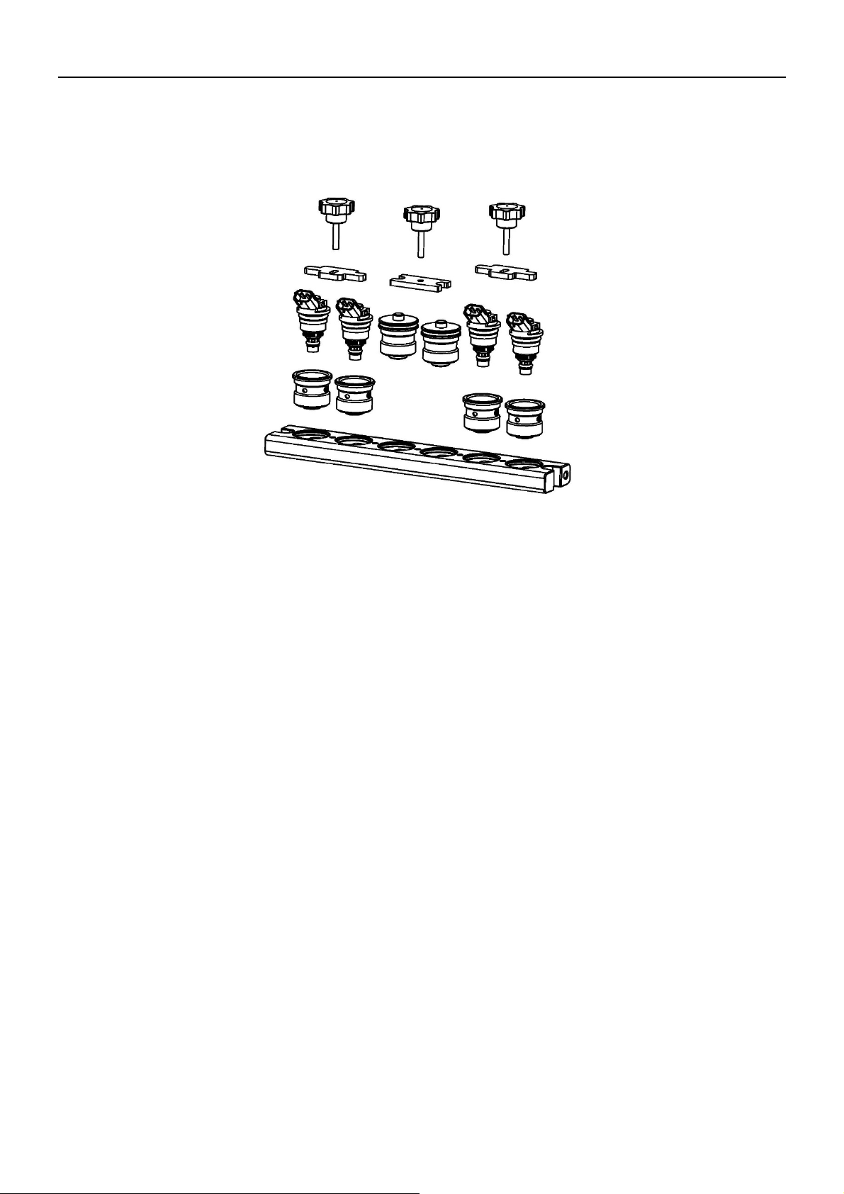
3.1 Installation of top-supply injectors
(
EFI/MPI/SFI
)
1) Choose the adapters according to the fuel top-supply injector from the coupler box and mount a proper O-ring on
it. Remember to apply a little lubricating fuel on the O-ring.
2) The adapters for fuel top-supply injector are 4 types:
Thread sealing type: here are with coarse thread and fine thread.
O-ring sealing type: here are with big hole and small hole.
3) If the injectors cannot be fixed because of the hole being bigger than the injector, need to sue the auxiliary support.
4) Need to adjust the relative position between the Knurled nut and adjustable screw so that the injectors can be fixed well
on the unit.
(Installation of top-supply injectors)
5
AJ600
Injector Cleaner & Tester
ANCEL
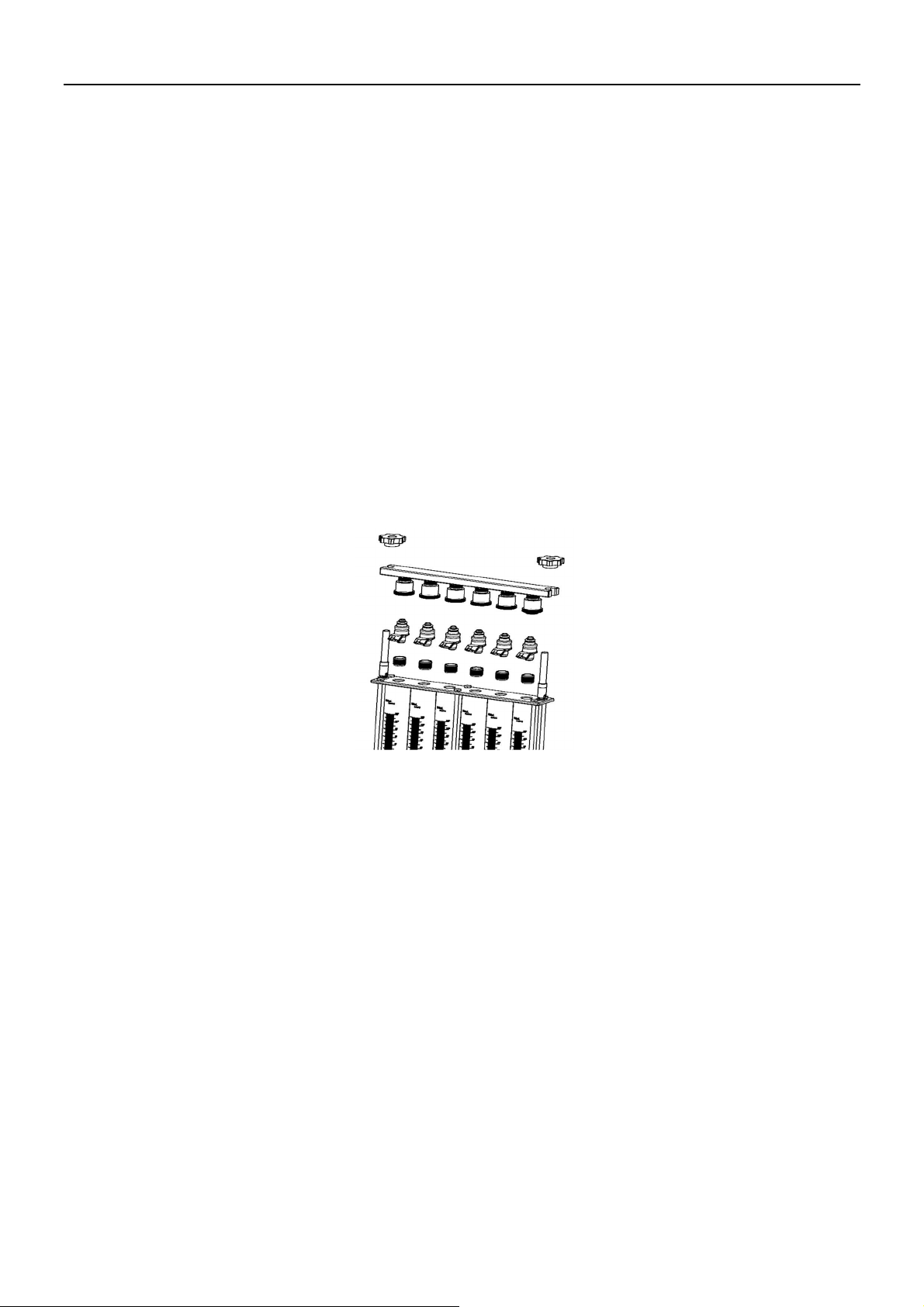
3.2 Installation of side-supply injectors
1) Choose proper couplers for side-supply injectors and proper O-rings, and mount them together.
2) Before fixing, best to apply a little lubricating fuel on the O-ring.
3) If some cylinder is not used, need to install the plug.
(Installation of side-supply injectors)
IV. Operating Procedures
4.1 Preparation
1) Remove the injector from the motorcycle engine to check the o-rings inside for damage. If it is be damaged
need to replace it. Put the outside of injector in gasoline or detergent, and wipe them with soft cloth after
cleaning the outside fuel sludge carefully.
2) Check the test liquid level to be sure there are enough test liquid inside tank. Pouring test liquid from the port
at the top left side of the unit and watch the liquid level in the fuel level viewer. In most cases, filled the liquid
up to 1/2 of the tank capacity.
3) Turn on the power switch on the right of the
Cabinet.
4) Pour ultrasonic detergent into the ultrasonic cleaning basin so that the needle valve of the injector is covered by
the detergent.
5) Connect the injectors with the right couplers.
• The main unit of the device uses test solution for uniformity / sprayability test, leakage test, injecting flow test and
auto. test. The ultrasonic cleaner uses the cleaning agent. Test solution and cleaning agent are not included in the
standard configuration and can be purchased separately.
4.2 Cleaning & testing sequences
Recommended to carry out the complete cleaning and testing procedures as the following order.
Ultrasonic cleaning;
Uniformity / Sprayability test;
Leakage test;
Injecting flow test;
Auto. test.
4.3 Procedure after work operation
1) Press [Drain] button on the control panel to drain test solution to a fuel container.
2) Switch off the power switch and unplug the power plug.
3) Use an fuel header to suck all cleaning agent in the ultrasonic cleaning pool, shown in Figure 4.2, and wipe the
pool with a soft dry cloth.

6
AJ600
Injector Cleaner & Tester
ANCEL
4) Wipe the table top of the machine with a soft dry cloth.
5) To avoid volatilization, all the test solution in the fuel tank should be discharged. If it can be used again, store it
in a safe place. If it is dirty and cannot be used any more, dispose it according to relevant regulations.
V. Operation
5.1 Resistance Test
1) Connect one end of the resistance measurement line to the interface on the right side of the device, and the other
end to the two electrodes of the fuel injector.
2) Start the machine, and press the key. The resistance value will be displayed on the screen.
3) If needed, measure several times to confirm the measured value.
4) After the measurement is completed, remove the fuel injector and the resistance measurement line.
5.2 Ultrasonic Cleaning
Injector Cleaner takes advantage of the penetrability and cavitation impact wave caused by ultrasonic wave traveling
through the medium to provide powerful cleaning on objects with complex shapes, cavities and pores, so that the
stubborn carbon deposits can be removed from the injectors.
Procedures
1) Place the injector/pump which has gone through surface cleaning in the launder.
2) Add enough injector detergent into ultrasonic cleaner so that the liquid level is about 20mm above the needle valve
of injectors / whole pump.
3) Plug the pulse signal wire to injector / pump respectively.
4) Select ultrasonic cleaning function and then set the time.
5) Press RUN key to start the procedure.
6) When the time is up, it will stop automatically as the beeper rings.
7) Take the injector / pump out of the launder and wipe them with a dry soft cloth. Get ready for next operation.
Note:
1) It is strictly forbidden to open the ultrasonic system under the circumstances that cleaning agent has not been added
into the ultrasonic cleaning pool. Otherwise, the ultrasonic equipment may be damaged easily.
2) It is strictly prohibited to immerse the pulse signal line connector along with the injector into the ultrasonic pool
for cleaning. Otherwise, the pulse signal line connector can be damaged easily.
5.3 Uniformity/Sprayability Test
Uniformity test is to find out the difference of the injectors injecting at the same working condition. This test can
indicate the comprehensive influences on the injector caused by electrical nature, bore variation and clogging. Spray
ability test is to inspect the spraying performance by observing the injectors.
Installing and testing procedures for injectors
1)
Note:
1) While testing, it can drain fuel by pressing DRAIN icon. At default, solenoid valve is set at the closed state.
Uniformity test can be done at this state. When DRAIN icon is pressed, solenoid valve will drain fuel.
2) The system pressure can be adjusted by pressing + or – at testing.
3) During operating, the user can select parameter, such as RPM or PW, and then press or key to achieve the
status of the simulation.
4) Good injectors may have identical injecting angle, uniform spraying but no jet. Otherwise, replace the injector.
5) In the sprayability test, a special electrical parameter--the minimum injection pulse width of injector--can be
tested, to compare the injectors on the same engine. That is to set cylinder No., start the test from minimum
injection pulse width, and then gradually increases the pulse width till the injector starts injection (observed with
the help of backlight). The value set at this moment is the minimum injection pulse width, so the difference of
7
AJ600
Injector Cleaner & Tester
ANCEL
minimum injection pulse width among these injectors could be observed.
Backflushing
Backflushing is limited to the top-supply injector by connecting the backflushing connector under uniformity /
sprayability test. Test solution enters from the outlet of the injector and flows out from the inlet during backflushing.
Backflushing can wash away the dirt inside the injector and dirt attached to the filter.
1) Find the backflushing connector (and select a supporting “O” ring to install it on the connector) installed below
the fuel separator;
2) Install the top-supply injector in reverse direction (outlet up, inlet down);
3) Select the corresponding coupling element under the injector according to the shape of injector;
4) Adjust the screws to fix the fuel separator and injector assembly in the fuel filler hole of the upper cover according
to the height of injector and tighten the compression screws (black) on both sides evenly;
5) It is recommended to press [Drain] button to drain the remaining fuel in the transparent tube to avoid overflow
of test solution before backflushing.
6) Connect the pulse signal line of the injector properly; set the operating parameters and press Run button to
execute backflushing function; the system pressure can be adjusted by + and – buttons on the control panel
during backflushing.
7) The system will stop automatically after completion of the cleaning.
(Installation for backflushing)
5.4 Leakage Test
Leakage test is to inspect the sealing conditions of the injector needle valve under system pressure and to find out if
the injector is dribbling
Procedures
Installation refer to Uniformity/ Sprayability Test.
1) Before doing leakage test, please press DRAIN key to drain the rudimental residual test liquid from the
measuring cup.
2) Select Leakage Test function and press Run key to start.
At this time the system pressure can be adjusted by pressing
+
and
–
key to observe dribbling from the injector
the pressure is adjusted preferably 10% higher than manufacturer’s specifications.
3) When the test is over, the equipment will automatically stop and the buzzer will ring simultaneously.
Note: In general the drip of the injector should be less than 1 drop within 1 minute (or in accordance with the
specifications). The default time of the system is 1 minute.
5.5 Injecting Flow Test
Injecting flow test is to check if the injecting flow in 15 seconds meets the specifications for injecting amount. The
deviation reflects the wear or clogging in the injector, instead of electrical parameter variation.
8
AJ600
Injector Cleaner & Tester
ANCEL
Procedures:
Installation refer to Uniformity/ Sprayability Test.
1) Before this test, press DRAIN icon to drain the test liquid from the measuring cup if there is any.
2) Choose Injecting Flow Test function and press Run key to start the test.
Adjust the fuel pressure by pressing
+
or
–
key according to the injector specification.
3) When the test is over, the equipment will stop automatically at the ring of the buzzer.
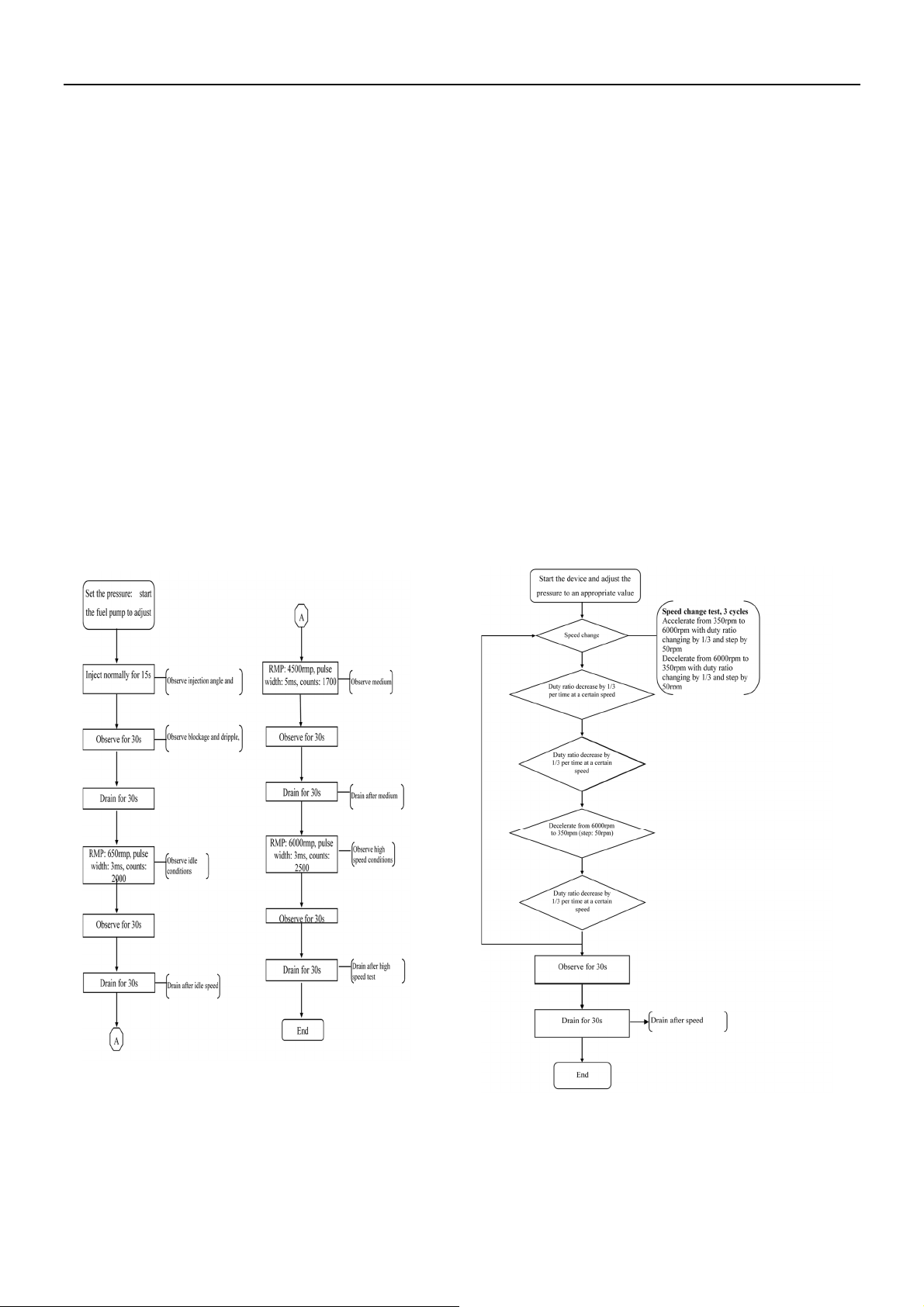
5.6 Auto. Test
Auto. test contains all above-mentioned tests (15-second injecting test, idle speed, middle speed, high speed, varying
acceleration, varying deceleration, changing pulse width test). This function can test more comprehensive
performance of injectors by simulating the various engine working conditions.
Procedures:
Installation refer to Uniformity/ Sprayability Test.
1) Before the test, press DRAIN icon to drain all the test liquid in the measuring cups if there is any.
2) Select AUTO function choose mode no. , then press Run key to start the test.
3) Adjust the fuel pressure by pressing + or – keys.
4) When the test is over, the equipment will auto stop at the ring of the buzzer.
There are 3 modes for auto. test: Mode 1, Mode 2 and Mode 3. Mode 1 and Mode 2 are shown below, while Mode 3
is to run Mode 2 after running Mode 1.
Mode 1
Mode 2
9
AJ600
Injector Cleaner & Tester
ANCEL
5.7 On-Vehicle Cleaning
After the motorcycle engine has been in operation for a period of time, its fuel flow may be blocked or become un-
smooth owing to buildup of dust and impurities in fuel channel. In addition, the carbon deposits and gum made by
combustion can easily adhere to the injectors, inlet and outlet ports, inlet and outlet hoses, throttle and combustion
chamber. So the fuel supply system, combustion chamber and injector of the engine must be cleaned on a timely basis.
Combustion Chamber cleaning is a solution that can save your time and labor.
Procedures:
1) Please check if there is test liquid or detergent inside the fuel tank before on-vehicle cleaning. If test liquid is in
the tank, replace it with detergent.
2) Blend the detergent with the fuel at a certain ratio, and fill the mixture into the fuel tank.
3) The connection of engine fuel pipes has been shown in “Connecting” below.
4) Select On-Vehicle Cleaning function, and set the cleaning time.
5) Press Run key to start the function, adjust the fuel pressure by pressing
+ or –
keys.
6) Start the engine to begin cleaning.
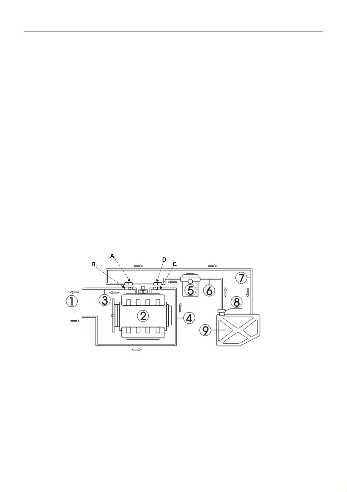
Connecting
There are two cases for the line connection: one is the connection with fuel-return hose and the other is the connection
without the fuel-return hose.
Connection with fuel-return hose:
1) Disconnect the fuel supply hoses (C, D) and fuel return hoses (A, B) of the engine fuel system (when disconnecting
the fuel line connectors, cover them with towels). Choose proper connectors and connect them to the B end and C
end separately, and then connect the other ends to corresponding return hose and outlet hose of the device.
2) Connect the two other disconnected ends (A, D) with a proper hose, or remove the fuel pump fuse, or disconnect
the power cable of engine fuel pump.
1- Injector Cleaner & Tester; 2-Engine; 3- Fuel-return hose from engine; 4- Fuel-inlet hose to engine;
5-Auto filter; 6-Engine fuel supply hose; 7-Engine fuel return hose; 8-Fuel pump; 9-Fuel tank
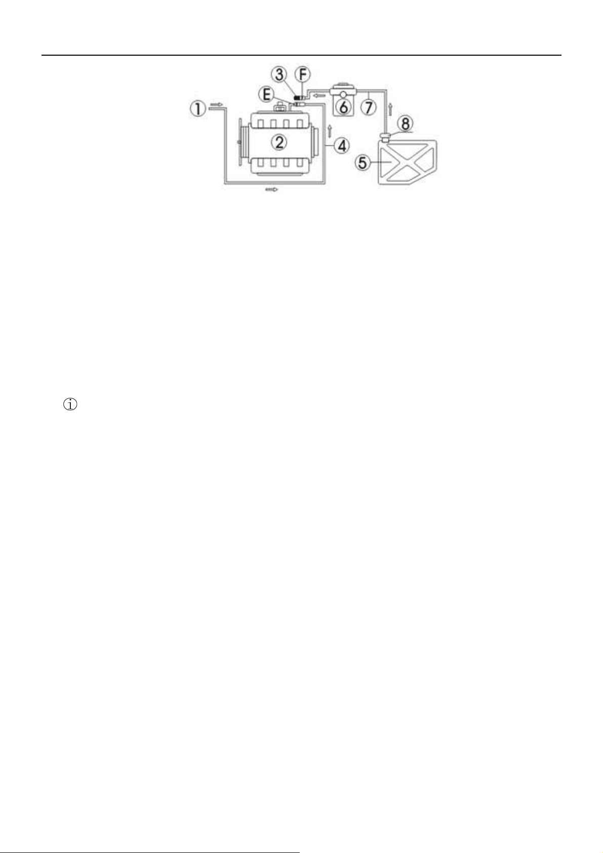
Connection without fuel-return hose:
1) Disconnect the fuel supply hoses (E, F) of the engine fuel system (when disconnecting the fuel line connectors,
cover them with towels), and then choose a suitable connector, connect it to the E end and reconnect the fuel
outlet hose of the device. Hang the fuel return hose.
2) Block the other end of the disconnected end (F) with a stopper (for fuel pump with fuel return function only)
or remove the fuse of fuel pump or disconnect the power cable of engine fuel pump.
10
AJ600
Injector Cleaner & Tester
ANCEL
1- Injector Cleaner & Tester; 2-Engine; 3-Stopper; 4- Fuel-inlet hose to engine;
5-Fuel tank;6-Fuel filter; 7- Engine fuel supply hose; 8-Fuel pump;
Tidy up after cleaning
1) After the on-vehicle cleaning is completed, turn off the ignition switch of the vehicle. Restitute the hose
connection, start the engine and accelerate properly to check if there is any fuel leakage at the connectors or in
the hoses.
2) Please clean the fuel tank and the lines of the device with test solution at the end of the on-vehicle cleaning, the
specific procedures are: drain the detergent left in the fuel tank first and dispose it according to its cleanliness.
Add a small amount of test solution into the fuel tank, connect the fuel outlet hose of the device to the fuel return
port and power on the device. Select “Leakage test” item and press RUN button to run the device for about 2∼3
minutes. After the running has stopped, drain the test solution from fuel tank and dispose the drained liquid
according to relevant regulations.
3) Clean up the site and tidy up the washing machine for later use.
Note:
1) When cleaning, care must be taken as the detergent is inflammable. Prepare at least one effective fire
extinguisher.
2) Be sure that all lines are well connected and there is no leakage before performing cleaning.
VI. Transporting and Storing
6.1
Transporting
1) Before being packed, the liquid inside the fuel tank should be drained completely to avoid overflowing as
transporting.
2) Move only by hand or lift with soft belt.
3) No package no lifting tools or long-distance transportation.
4) To prevent the unit from shocking and knocking, make sure it is on the base seat and in the packing case during
transportation. Firstly pack the unit with the matter similar with plastic strip and add the filling material (such as
foam or sponge, etc.) between the unit and packing case to avoid scratching the surface when the unit shakes.
5) Make sure that the maximum incline angel does not exceed 45℃. Do not place the unit up-side-down.
6.2
Storing
1) Store only in dry area and keep away from water before the unit is unpacked.
2) Store the machine in well-ventilated area and do not expose it to direct sun shine or rain.
6.3
Installation Environment
1) Keep a distance of no less than 200mm between the unit and any wall or other substance. The unit should be put in well-
ventilated area. Make sure the temperature is within -10℃+40℃.
2) The unit has been well grounded for safety operation. Please confirm that the power socket is also well grounded.

11
AJ600
Injector Cleaner & Tester
ANCEL
VII. Troubleshooting & Precautions
7.1
Troubleshooting
1) The unit does not correspond when it is switched on.
2) Check the fuse at lower right side of the unit and replace it if it is damaged or broken.
3) There is leakage in the fuel separator coupler.
4) Fuel leaked at coupling element of fuel separator. Please check whether the “O” ring installed matches and if it deformed or
damaged. If it does not match or is damaged, please change it. The two black adjusting screws should not be too tight, which
may also cause the coupling element of fuel separator to leak fuel.
5) Draining the test liquid in glass tube thoroughly requires pressing the DRAIN icon more times.
6) The solenoid valves will stop automatically after 15 seconds and it is necessary to drain more times if there is more liquid.
7.2
Precautions
1) In order to avoid electric shock, keep away from the damp part of a working unit and avoid exposing it to the rain.
2) To ensure operation safety, please make sure that equipment has been connected to ground well.
3) Do not operate equipment with a damaged cord or if the equipment has been dropped or damaged until it has been examined
by qualified service personnel.
4) Equipment use is strictly prohibited fireworks, and posted “No smoking” and “Flammable hazard warning” signs.
5) Please operate the unit according to the operation procedures in the manual. Only use the accessories recommended by the
manufacturer.
6) ALWAYS WEAR SAFETY GOGGLES. Common used glasses are NOT safety glasses.