
-
- 1 -
-
Working Condition and Specification
1.1 Working Condition:
Powersupply: AC220V±10%
Frequency: 50HZ±0.5
Humidity:
<
85%
Environment Temperature:0℃~+40℃
Magnetic Field: <400A/m
Sparkand fire is prohibited.
2.2 Specifications:
Fuel Tank Capacity:2000 ml
Capacity ofMeasuring Cylinder: 125 ml
Speed Range: 0~7500 rpm
Injecting Times: 0~9900 Step: 100ms
PWMPulse: 0~20.0 ms Step: 0.1 ms
System Pressure: 0~0.6Mpa (adjustable)
Time: 0~20 minute (adjustable)
Power of Ultrasonic Cleaning: 70W
Frequency ofUltrasonic Cleaning: 28 KHZ±0.5 KHZ
-
- 2 -
-
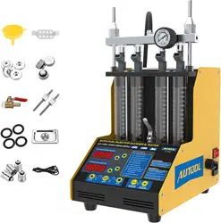
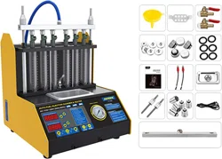
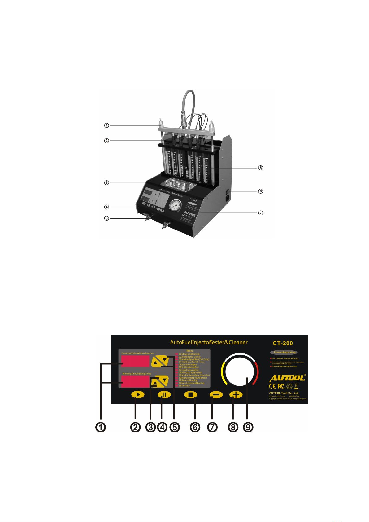
II Structure
2.1 Structure
1. Fasten bolt 2. Fuel distributor 3. Ultrasonic trough
4. Pressure meter 5. Measuring 6. Power switch
7. Operation panel 8. fuel outlet valve
2.2 Operation Panel
1. LED screen

-
- 3 -
-
2. Start: To run the function that selected;
3.Arrowkey: To adjust pulse working time and injection times;
4. PAUSE
5. Arrowkey: To select function item and adjust pulse width ;
6. STOP
7. Pressure down
8. Pressure up
9. Pressure Meter
Ⅲ
Operation
3.1 Ultrasonic Cleaning
3.1.1 Preparation
1
)
Move the injector from the car. Check and make sure that the seal ring
of the injector is in good condition. If not, please replace it to avoid the
leakage. Clean out side ofinjector carefully by gasoline or cleaning fluid.

-
- 4 -
-
2)Connect the machine to power supply and turn it on.
3)Put the cleaning frame on the ultrasonic groove, and put the injector
into the whole ofthe frame.
3.1.2 Steps
01 Ultrasonic Cleaning
1
)
Pour proper quantity cleaning fluid into ultrasonic groove.
2)Connect the actuation cable to the injector needed to be cleaned.
3) Press Left or Right Arrow key to select “Ultrasonic Cleaning” from
panel, then press “RUN”key.
4)Press Left or Right Arrowkey to set up working time(default time is 10
minutes).
5
)
Press “RUN”key. (You can press PAUSE or STOP at any time during the
operation process.)
6)After the cleaning is completed, it will stop automatically.
7
)
Take the injector out ofthe ultrasonic groove.
NOTE:
1. During the cleaning, get the injector close to ear, listen carefully, you
may hear the intermittent sound ofclosing and opening of the
injector’s valve, otherwise the injector’s valve is blocked.
2. Please do not turn on the ultrasonic trough when there is not clean
fluid in the trough, otherwise the machine will be damaged.
3.2 Injector Test
This function is to testthe condition of atomization, drop, block, spray
angle,and uniformity ofthe injector.
-
- 5 -
-
3.2.1 Preparation
1)Pour about 1900ML test fluid into the machine through measuring
cylinder.
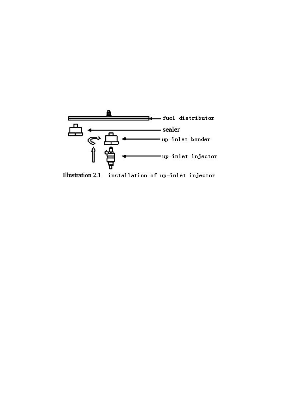
2)Install the injector
Installation of Up-inlet Injector
a. Take the coupler and plugs fromthe toll drawer and install them to fuel
distributor.
b.Put some grease on the “O”ring of the injector, and install it into the
coupler of the fuel distributor.
c. Put the fuel distributor and injector on the machine and fasten it by
fastenbolt.
(
For some special injector, it need to use lengthened bolt,
washer to fasten it.)
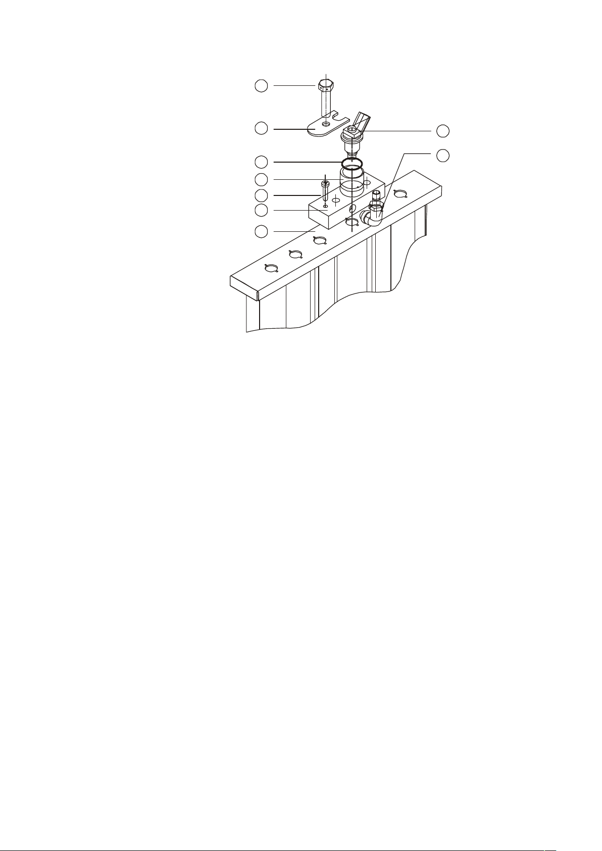
Installation of Side-feed Injector
-
- 6 -
-
1
2
3
4
5
6
7
8
9
Installation Diagram
a. Select the suitable coupler④ and “O”loop③, and then put the “O” loop
on the coupler. (Puta little lubricant on the couplerand the “O”loop.)
b. Put the injector⑨ into the coupler, and then put them together into the
fuel distributor⑥.
c. Install the hold plate
②
. Tighten the screw
⑤
on the hold plate. Adjust
the suitable height by screw④.
d. Install the fuel distributor and injector to the fuel distributor rack⑦.
e. Connect the adaptor of black hose with the male terminal
⑧
on the fuel
distributor. Connectthe drive wire of injector, and prepare to test.
3.2.2 Steps
02 Idle Speed Test
1)Connect black hose (outlet) to inlet port of the fuel distributor, and
then connect the actuation cable to the machine.
2)Press Left or Right Arrow key to select Idle Speed Test, then press RUN

-
- 7 -
-
key.
3)Press Left or Right Arrow key to set up working time. (Normally, it is 2
minutes.)
4)Press RUN key.
5)Turn Pressure Adjusting Knob until the pressure is 0.25-0.3MPa..
6)Press Left or Right Arrow key to select properinjection pulse (default
value is 3MS).
7)When the working time is zero, the machine will stop.
8)Release the fluid into the pump after test is completed.
03 Medium Speed Test
1)Press Left or Right Arrow key to select Medium Speed Test.
2)Press RUN key.
3)The next steps are the same as what listed in 02 Idle Speed Test.
04 High Speed Test
1)Press Left or Right Arrow key to select High Speed Test.
2)Press RUN key.
3)The next steps are the same as what listed in 02 Idle Speed Test.
05 Accelerating Test
1)Press Left or Right Arrow key to select Accelerating Test.
2)Press RUN key.
3
)
The next steps are the same as what listed in 02 Idle Speed Test.
NOTE:
1. System pressure, working time and pulse width are set up
automatically by system itself. (Default working time cycle is 10

-
- 8 -
-
seconds.)
2. System will automatically simulate 3 times accelerating cycle from 750
RPM to 7500 RPM to test the injection condition ofthe injector.
06 Shifting Speed Test
1)Press Left or Right Arrow key to select Shifting Speed Test.
2)Press RUN key.
3)The next steps are the same as what listed in 02 Idle Speed Test.
NOTE:
1. System pressure, working time and pulse width are set up
automatically by system itself. (Default working time cycle is 10
seconds.)
2. System will automatically simulate 3 times of engine condition of750
RPM, 4000RPM, and 7500 RPM to test the injection condition of the
injector.
07 Leakage Test
1)Press Left or Right Arrow key to select Leakage Test.
2)Press RUN key.
3)The next steps are the same as what listed in 02 Idle Speed Test.
NOTE:
1. Default pulse width is 3ms.
2. System simulates 0.3Mpa system pressure to test leakage.
08 Idling Spray Value Test
1)Press Left or Right Arrow key to select Idling Spray Value Test, then
press RUN key.

-
- 9 -
-
2)Press Left or Right Arrow key to set up injecting time (account time)
3)The next steps are the same as what listed in 02 Idle Speed Test.
NOTE:
To simulate the injecting condition after working for a certain times in Idle
speed
09 Medium Speed Spray Value Test
1)Press Left or Right Arrow key to select Medium Spray Value Test, then
press RUN key.
2)The next steps are the same as what listed in 08 Idling Spray Value Test.
10 High Speed Spray Value Test
1)Press Left or Right Arrow key to select Medium Spray Value Test, then
press RUN key.
2)The next steps are the same as what listed in 08 Idling Spray Value Test.
NOTE
:
1. Check the deviation of the spray value: test the spray value in different
rpm, checkthe spray value in different measuring cylinder, the
deviation should not exceed 2% or refer the specification of the injector.
2. Leakage test: leakage should not occur within 1 minute under 0.3MPA
system pressure.
3.3 Reverse Flushing
The flush fluid go into the injector through its outlet and go out through
its inlet, so that it can clean the filth inside, which can not be cleaned by
normal way.

-
- 10 -
-
3.3.1 Preparation
1)Pour about 1900ML test fluid into the machine through measuring
cylinder.
2)Install the injector.
a. Screwthe reverse flushing bonder (5)on the fuel distributor.
b.Put reverse flushing “O”ring on the injector, and install injector by
reverse direction.
c. Put the reverse flushing bonder (9)on the cylinder bracket.

-
- 11 -
-
d. Fasten the injector on the machine (see Fig. above).
3.3.2 Steps
11 Reverse Flushing
1)Connect black hose (outlet) to inlet port of the fuel distributor, and
then connect the actuation cable to the machine.
2)Press Left or Right arrowkey to select Reverse Flushing.
3)Press RUN key (default testtime is 1 minute).
4)Turn Pressure Adjusting Knob until the pressure is 0.25-0.3MPa.
5)When the working time is over, the machine will stop.
6)Release the fluid into the pump after test is completed.
Note:
1. Only up-inlet injector can fit Reverse Flushing.
2. Need not set up pulse width, system use default value.
3. Please make sure the test fluid is clean, so that the injector will not be
blocked.
3.4 Non-dismantle Cleaning(optional function)
To clean the whole fuel system of the engine, including fuel supply system,
burning room and the injector. .
3.4.1 Preparation
1)Move the screwon the bottom of test fluid bottle, and release all test
fluid.
2)Open the cover ofthe engine chamber. Find out the fuel supply hose
and return hose of the fuel system.
3.4.2 Steps

-
- 12 -
-
12 Non-dismantle Cleaning
1)Take the red long hose from the accessories box. Connect one end to
return hose ofthe engine, and the other end to the return hose port of
the machine.
2)Run the engine, and checkthe testfluid bottle. When the level is up to
600-800ML,stop the engine.
3)Take the long blue hose from the accessory box. Connectone end to
the high pressure port ofthe machine,and the other end to the supply
hose of the engine fuel system.
4)Move the pump relay ofthe engine or short connect the fuel circuit of
the engine fuel pump.(In this case, please make sure the cover offuel
tank is open.)
5)Turn on the machine. Press Left or Right Arrowkey to select
Non-dismantle Cleaning, and set up the time as 20-30minutes.
6)Adjust system pressure, (normally the pressure should between
0.25-0.3Mpa).
7)Press RUN key, and turn on the engine after several seconds.
8)Pour Non-dismantle cleaning fluid into one of the measuring cylinder
ofthe machine (0.5 bottle for 4 cylinder engine, 0.75 bottle for 6
cylinder engine, and one bottle for 8 cylinder engine).
9)Adjust engine speed, make it to run 1-10 minute under idle speed,
10-15 minutes under medium and high speed;, and run under idle
speed again in the rest ofthe time.
10) When the setting time is zero, the machine will stop automatically.

-
- 13 -
-
Remove the hose and let the engine back to its normal condition.
11) Turn on the engine and run it for 2-3 minutes under high speed, and
checkif there is any leakage occurs.
Note:
1)The Non-dismantle cleaning fluid is inflammable, so please take care to
avoid any hurt.
2)Make sure that all the connections are in good condition before
performance the cleaning.
IV Tidy and Maintenance
4.1 Tidy
Step 1: Shut down the power supply.
Step 2: Put the testand cleaning fluid back to the original bottle, and
clean the machine with dry soft cloth.
Step 3: The testing fluid in tank should be put backto original bottles for
preservation.
4.2 Maintenance
Exchange Cleaning Fluid
After being used for long time, the fluid must be changed to avoid that
the
injector is blocked by the impurity.
Exchanging Process
Step 1: Remove the fluid-release screwcap to let all the liquid out.
Step 2: Pour some newfluid to wash the inside and then release it.
Step 3: Fixthe screwcap on, and add two bottles ofnewcleaning fluid.

-
- 14 -
-
Exchange Protector Tube
Step 1: The protector case is on the unit’s power receptacle.
Step 2: Open the case, and then you will see the tube.
Step 3: Change a newone if the tube was melted.
Notice
1. The measuring cylinders are made of quartz glass, and fragile. No
striking!
2. Before start the unit, please checkthe power supply, connector plugs
and protector tube to ensure that they are in good condition.
3. Warranty will be cancelled if dismantle the unit without permission.
4. Damage will occur if run the ultrasonic cleaning function without
special cleaning fluid.
5. Before exchanging the newtesting fluid, the used one must be
released entirely, then adding two bottles (1800ml) for using.
6. Taking use of the special testing or cleaning fluids which designed for
unit, for other ones will flake the surface painting coat off..
7. Never using coal oil, petrol or thinner for as cleaning or testing fluid.
8. Never mixthe testing and cleaning fluids for usage.
9. The trouble caused by using other fluids or liquid is beyond the

-
- 15 -
-
repairing guarantee range.
V The Cleaning and Testing Fluids
Safety and innocuity, the fluids are specially designed for the unit and
composed of sediment controlling fluid, with high stability and oxidation
resistance, resuming injector unimpeded, normal spray, eliminate the
troubles of idling unsteadiness, accelerating hard, and improve
combustion performance, saving the petrol cost.
To avoid burning the unit's core oil pump and fretting the oil piping
system, the fluids are kept from any acid or base component from any
acid or base component.

-
- 16 -
-
VI Warranty
Thank you for choosing this product. Following service and warranty
apply:
1. This product is warranted to be free fromdefects for a period ofone
year from date of purchase.
2. For the repairs out of warranty period, we only charge the cost ofparts.
3. For updating the unit, we only charge the cost.
4. Ifyour unit needs repair or replacement parts, contact your local
distributor or our company. We will serve you ASAP.
5. To validate your warranty, please complete the warranty card attached
to your unit, and return it. We will keep your record, and serve you.
6. Followings do not apply to our warranty:
1)The broken of measuring cylinder, actuation cable, couples and

-
- 17 -
-
adaptors, pressure meter.
2)The consumption: test fluid, cleaning fluid, Non-dismantle cleaning
fluid.
3)The broken of the ultrasonic system caused by turning on the
ultrasonic trough when there is not cleaning fluid in it.
4)Pump broken caused by not changing test fluid for long time.
5)Pump broken caused by using test fluid that is not approved by our
company.
6)Pump broken caused by wrong using of the test fluid or cleaning fluid.
7)Broken caused by incorrect operation.
Web: www.autooltech.com
Tel: 0086-755-27813404