
Fuel Injector Cleaner & Tester
AUTOOL C T150
www.autooltech.com
User Manual
用户手册
企业标准 / Corporate standard: Q/OR 002-2023

COPYRIGHT INFORMATION
Copyright
Trademark
Manual are either trademarks, registered trademarks, service
marks, domain names, logos, company names or are otherwise
the property of AUTOOL or its affiliates. In countries where any of
the AUTOOL trademarks, service marks, domain names, logos
and company names are not registered, AUTOOL claims other
rights associated with unregistered trademarks, service marks,
domain names, logos, and company names. Other products or
company names referred to in this manual may be trademarks of
their respective owners. You may not use any trademark, service
mark, domain name, logo, or company name of AUTOOL or any
third party without permission from the owner of the applicable
trademark, service mark, domain name, logo, or company name.
You may contact AUTOOL by visiting AUTOOL at https://www.au-
tooltech.com, or writing to aftersale@autooltech.com, to request
written permission to use materials on this manual for purposes or
for all other questions relating to this manual.
●
●
●
●
All rights reserved by AUTOOL TECH. CO., LTD. No part of this
publication may be reproduced, stored in a retrieval system, or
transmitted in any form or by any means, electronic, mechanical,
photocopying, recording or otherwise, without the prior written
permission of AUTOOL. The information contained herein is
designed only for the use of this unit. AUTOOL is not responsi-
ble for any use of this information as applied to other units.
Neither AUTOOL nor its affiliates shall be liable to the purchaser
of this unit or third parties for damages, losses, costs, or
expenses incurred by the purchaser or third parties as a result
of: accident, misuse, or abuse of this unit, or unauthorized modi-
fications, repairs, or alterations to this unit, or failure to strictly
comply with AUTOOL operating and maintenance instructions.
AUTOOL shall not be liable for any damages or problems
arising from the use of any options or any consumable products
other than those designated as original AUTOOL products or
AUTOOL approved products by AUTOOL.
Other product names used herein are for identification purpos-
es only and may be trademarks of their respective owners.
AUTOOL disclaims any and all rights in those marks.
CAUTIONS
Warning
Since the test device is part of quartz glass, it is easy to break,
so do not place other objects around the equipment to avoid
bumping and breaking.
If there is no digital display after power on, please check
whether the power supply is powered; if so, check whether the
plug is connected firmly, or whether the fuse is blown. If it is not
broken, and the switch is still invalid after pressing the switch
several times intermittently, please contact the manufacturer
and must not disassemble it by yourself, otherwise our compa-
ny will not provide warranty.
When no cleaning agent is added to the ultrasonic tank, it is
strictly prohibited to open the ultrasonic cleaning item to avoid
damage to the ultrasonic system.
Every time the test solution is changed, it must be cleaned up,
and then 1L of new test solution should be added.
The use of unqualified testing agent will cause corrosion of the
oil pump, oil supply pipeline and failure of the pressure gauge.
Using other cleaning agent and testing agent will cause the
equipment surface coating to peel off.
It is strictly forbidden to use kerosene, gasoline or other testing
agent and cleaning agents as testing agent and cleaning
agents for this machine. Otherwise, the “O” ring and pipeline
rubber parts in the equipment will be damaged, causing
leakage.
The cleaning agent and testing agent should not be mixed up.
Before using the instrument, please read this manual careful-
ly for proper operation.
1
TABLE OF CONTENTS
Product Introduction.......................................................................................... 2
Overview......................................................................................................... 2
Main functions................................................................................................. 2
Main features .................................................................................................. 2
Working environment ...................................................................................... 3
Technical parameters...................................................................................... 3
Product Structure............................................................................................... 4
Structure diagram............................................................................................ 4
Operation panel diagram................................................................................. 5
Operation Process ............................................................................................. 7
Ultrasonic cleaning.......................................................................................... 7
Injector diagnostic ........................................................................................... 8
Storage And Maintenance ................................................................................. 13
Storage............................................................................................................ 13
Maintenance Service.......................................................................................... 14
Maintenance.................................................................................................... 14
Warranty .............................................................................................................. 15
Warranty access.............................................................................................. 15
Disclaimer ....................................................................................................... 15
Return & Exchange Service .............................................................................. 16
Return & Exchange......................................................................................... 16

2
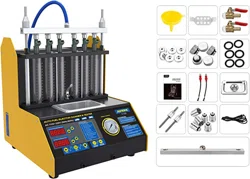
Fuel injector diagnostic and cleaning equipment is a mechatronics
product that combines ultrasonic cleaning technology and micro-
computer oil pressure closed loop control cleaning and detection
technology. This product simulates various operating conditions
of the engine, and cleans and inspects the fuel injectors of various
automobiles and motorcycles. This equipment is the necessary
and preferred equipment for the automobile and motorcycle repair
and maintenance industry, research and teaching and training
departments.
PRODUCT INTRODUCTION
Overview
Main
functions
Ultrasonic cleaning:
Ultrasonic cleaning can be performed on single or multiple
injectors at the same time, which can remove the attachments
and internal blockages on the injectors.
Uniformity detection:
To detect the uniformity of the injection volume of each injector.
Atomization observation:
Using the background light, you can observe the spray atomi-
zation situation of the nozzle in a comprehensive and careful
manner.
Tightness test:
It can detect the tightness and dripping of the fuel injector
under high pressure.
Fuel injection volume detection:
It can detect the fuel injection volume of the fuel injection
nozzle under specific working conditions (such as the same
time and the same number of times).
●
●
●
●
●
Main features
Using ultrasonic powerful cleaning technology, strong cleaning
ability.
Using electronic pressure regulating control technology, stable
oil pressure and wide adjustable range.
Use high-quality oil pump to ensure long-term stable use.
●
●
●

Power Supply
Frequency
Relative Humidity
Environment Temperature
AC 110/220V ±10%
50HZ ±0.5
<85%
0°C~+40°C
External Magnetic Field Strength
No open flames are allowed around
<400A/m
3
Working
environment
Package Size
RPM Range
PWM Pulse Width
Time Settings
395*295*370mm
Package Weight
10kg
0~7500RPM
0~20ms
0~10min
Cleaning Frequency
40kHz
Cylinder Volume
Injection Times
System Pressure
Ultrasonic Cleaning Frequency
140ml
0~9900times, step 100ms
0~0.6Mpa
28KHZ ±0.5KHZ
Fuel Tank Capacity
2500ml
Product Size
300*220*320mm
Technical
parameters
The use of high-definition digital tube display makes the opera-
tion clear and easy to learn.
The oil tank liquid level is displayed visually, and the detection
liquid can be recycled.
Bright background light, you can clearly see the various
situations of the fuel injector when it is working.
It has replaceable composite joints suitable for a variety of
vehicle types.
The testing time and pulse width of the fuel injector can be
adjusted as desired within the allowed adjustment range.
●
●
●
●
●

4
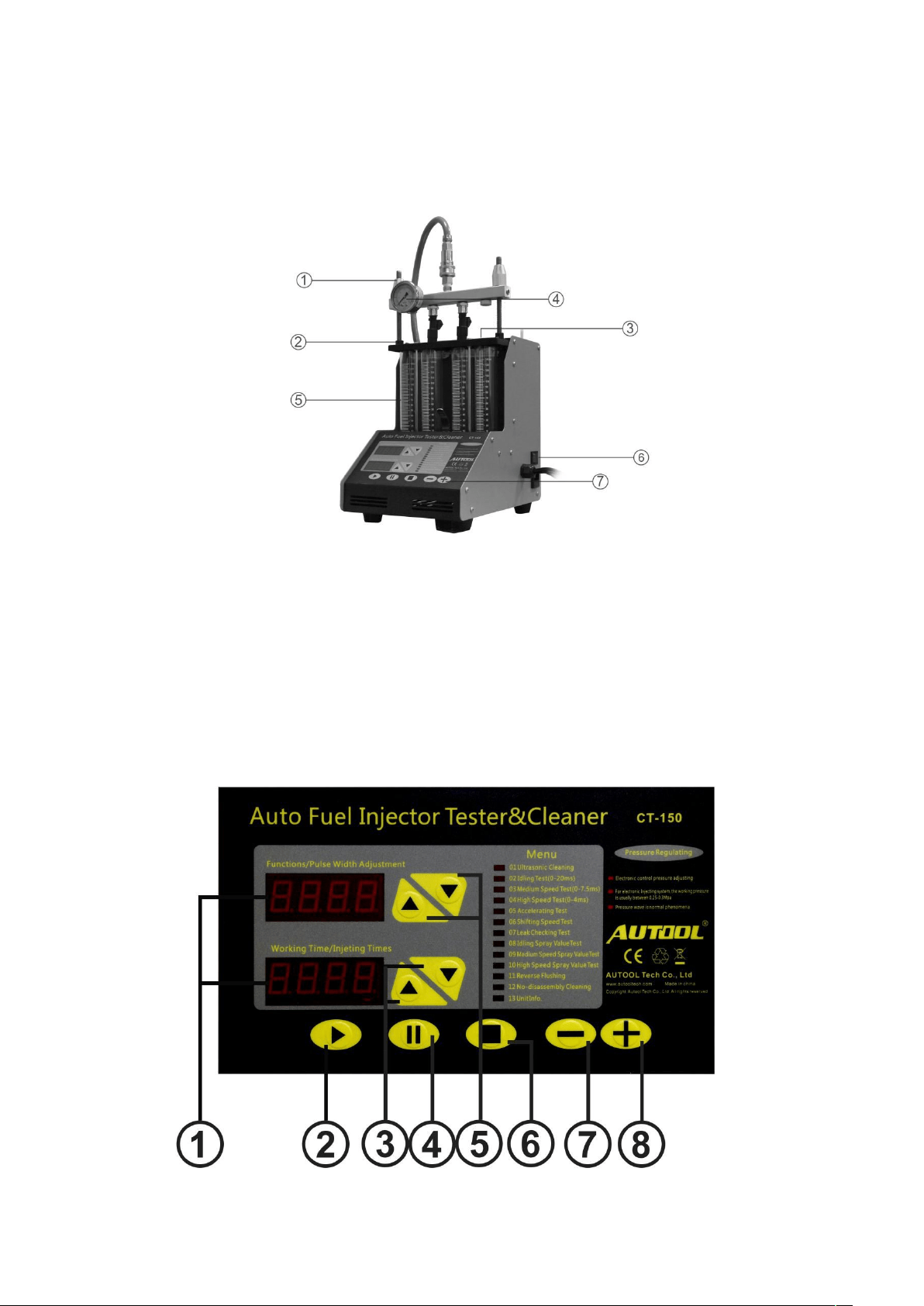
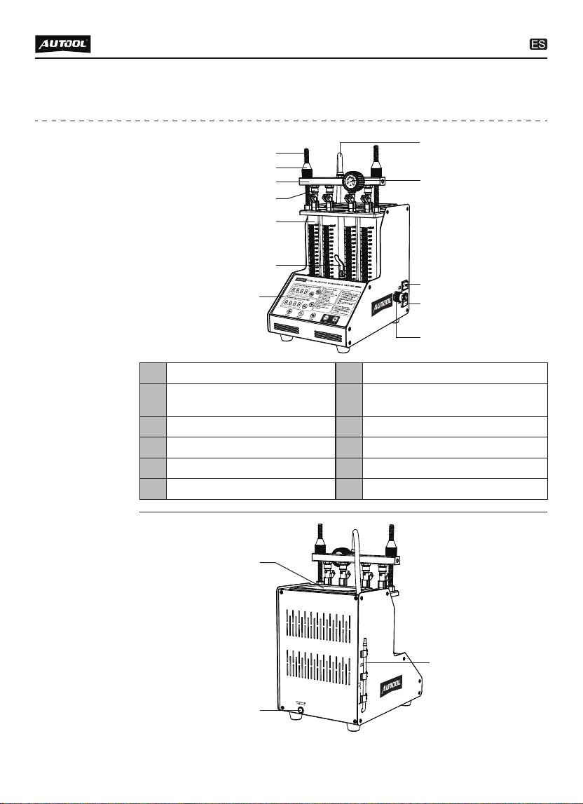
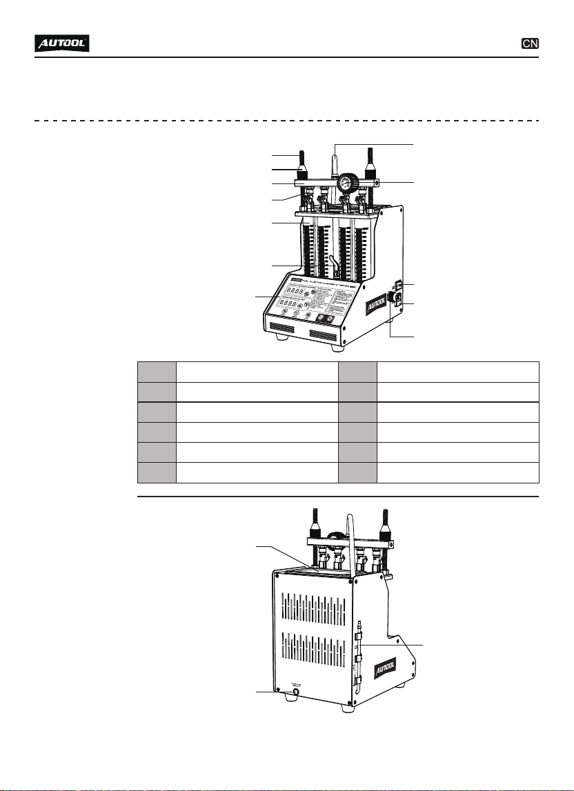
PRODUCT STRUCTURE
Structure
diagram
Operation panel
Pressure gauge
7
9
Oil outlet pipe
Power switch
8
10
Power socket
11
Lock pole
Oil rail
1
3
Lock nut
Top oil inlet connector
2
4
Oil drain handle
6
Signal wire
12
Glass measuring cylinder
5
15
14
13
10
7
11
12
6
5
2
1
4
3
9
8
5
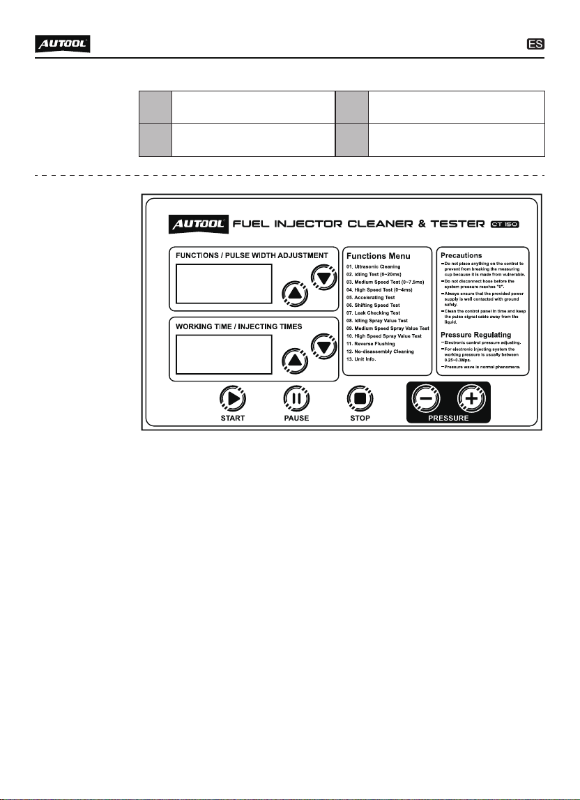
Operation
panel
diagram
Ultrasonic cleaning tank
Testing agent liquid level
13
15
Cleaning agent drain valve
14
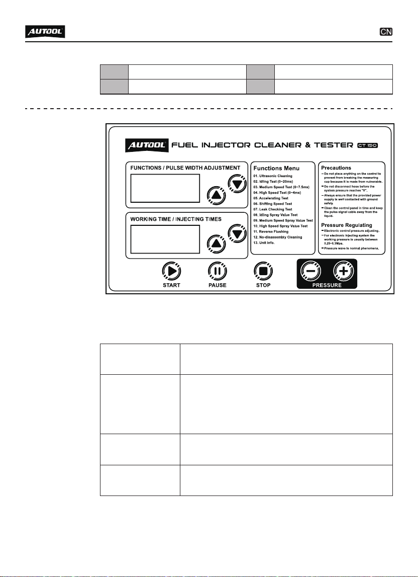
Pulse width / Function window:
Display the selected function item when the function is select-
ed, and display the pulse width of the injector when working.
Time window:
Display the working time of the fuel injector and the number of
fuel injection.
Pulse width adjustment button:
Adjust the pulse width of the injector when working.
Press up to increase the working pulse width of the injector
when cleaning the injector.
Press down to clean the injector to reduce the working pulse
width of the injector.
Time / Time adjustment button:
Adjust the working time of the injector and the number of
injections.
Press up to increase the working time of the injector / the
number of injections.
Press down to reduce the working time of the injector / the
●
●
●
●
●
●
●
●

6
number of injections.
Start button:
Press to execute the selected work item.
Pause button:
Temporarily stop the selected work item after pressing.
Stop button:
Stop the selected work item and return to the selected work
item.
Function selection button:
Select work item.
Press up to select work item.
Press the down to select the work item.
Pressure adjusting knob:
Adjust pressure change.
Turn clockwise to increase the pressure value.
Turn counterclockwise to decrease the pressure.
●
●
●
●
●
●
●
●
●

7
OPERATION PROCESS
Ultrasonic
cleaning
Ultrasonic cleaning is to use the penetrating and cavitation shock
waves generated when ultrasonic waves propagate in the medium,
and powerfully clean objects with complex shapes, cavities and
pores to completely remove stubborn carbon deposits on the fuel
injector.
Preparation
Remove the fuel injector from the vehicle and check whether
its rubber seal is damaged. If it is damaged, it should be
replaced in time before the cleaning test to avoid leakage
during the test. Then put the fuel injection nozzle into the
cleaning agent, carefully remove the external grease and wipe
it with a soft cloth.
Turn on the power and turn on the power switch on the side of
the main unit.
Put the cleaning bracket in the accessories into the ultrasonic
cleaning tank, and place the wiped fuel injector in the cleaning
bracket positioning hole of the ultrasonic tank.
●
●
●
Methods And Steps
Add an appropriate amount of cleaning agent to the ultrasonic
tank and spread the cleaning agent over the bottom of the
cleaning stand.
Insert the plugs of the drive wires into the injector sockets in
turn. (Special fuel injectors need to be connected with an
adapter cable)
Press the item selection up and down keys to select the “01
Ultrasonic Cleaning” item, and then press the working time up
and down keys to set the time. (The system defaults to 10
minutes, if you need to modify the time, you can use the up and
down keys to change)
Press the start button and turn on the ultrasonic cleaning
switch on the side of the device to start cleaning. When
working, you can press the pause button to suspend work or
press the stop button to exit.
During the cleaning process, the heating switch on the side of
●
●
●
●
●

8
NOTE
During the cleaning process, you can hear the intermittent
(approximately 5 seconds) vibrating sound when you take the
fuel injector out and put it to your ear, so you can judge whether
the fuel injector is working normally.
Ultrasonic cleaning is strictly prohibited when there is no
cleaning agent in the ultrasonic tank to avoid equipment
damage.
Only the ultrasonic cleaning agent dedicated to cleaning the
fuel injection nozzle can be added to the ultrasonic tank, and
other reagents cannot be used instead, otherwise any
malfunctions and damages caused will not be covered by the
warranty.
the equipment can be turned on to improve the cleaning effect.
The working time gradually decreases. When it is 0, the system
automatically stops.
Take out the fuel injection nozzle from the ultrasonic tank, wipe
the cleaning liquid on it with a soft cloth, and prepare for the
next job.
●
●
Injector
diagnostic
This function is to detect the atomization, dripping, blockage, fuel
injection angle status of the fuel injectors and the size and
balance of the fuel injection of each fuel injector at different
speeds.
Preparation
Confirm that the oil drain handle is open, use the funnel in the
accessories to add the test liquid to the equipment through the
glass window, and pay attention to control the flow rate during
the addition to avoid overflow.
Add 1 bottle (about 1000ml) of testing agent each time.
Install the fuel injector.
●
●
●

9
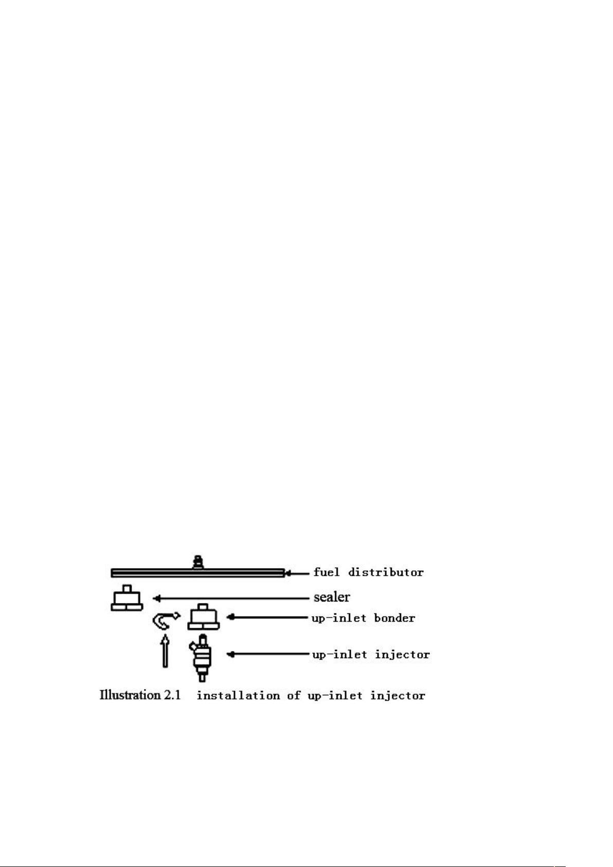
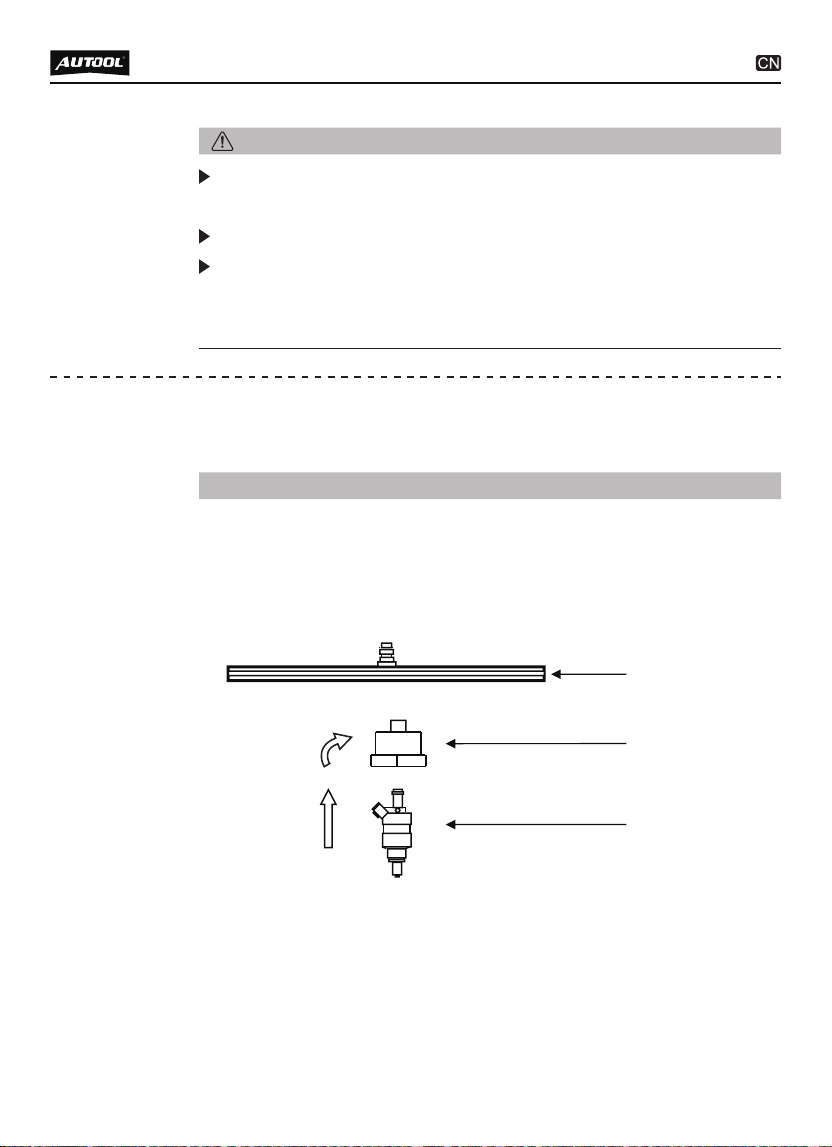
Select the top oil inlet connector from the accessories and
install it into the oil separator.
Install the fuel injector in the forward direction (Apply a little
grease on the “O” ring of the fuel injector)
Put the horizontal end of the oil separator and the fuel injector
on the upper plate seat, and tighten the two ends with the
locking rod. Ready to test.
●
●
●
Methods And Steps
02 Idle Speed Test
Confirm that the injector to be tested has been installed
properly and the signal wire has been plugged in.
Select “02 Idle Speed Test”.
Press the working time up and down keys to set the time.
(Generally set to 2 minutes)
Press the start button to start work.
●
●
●
●
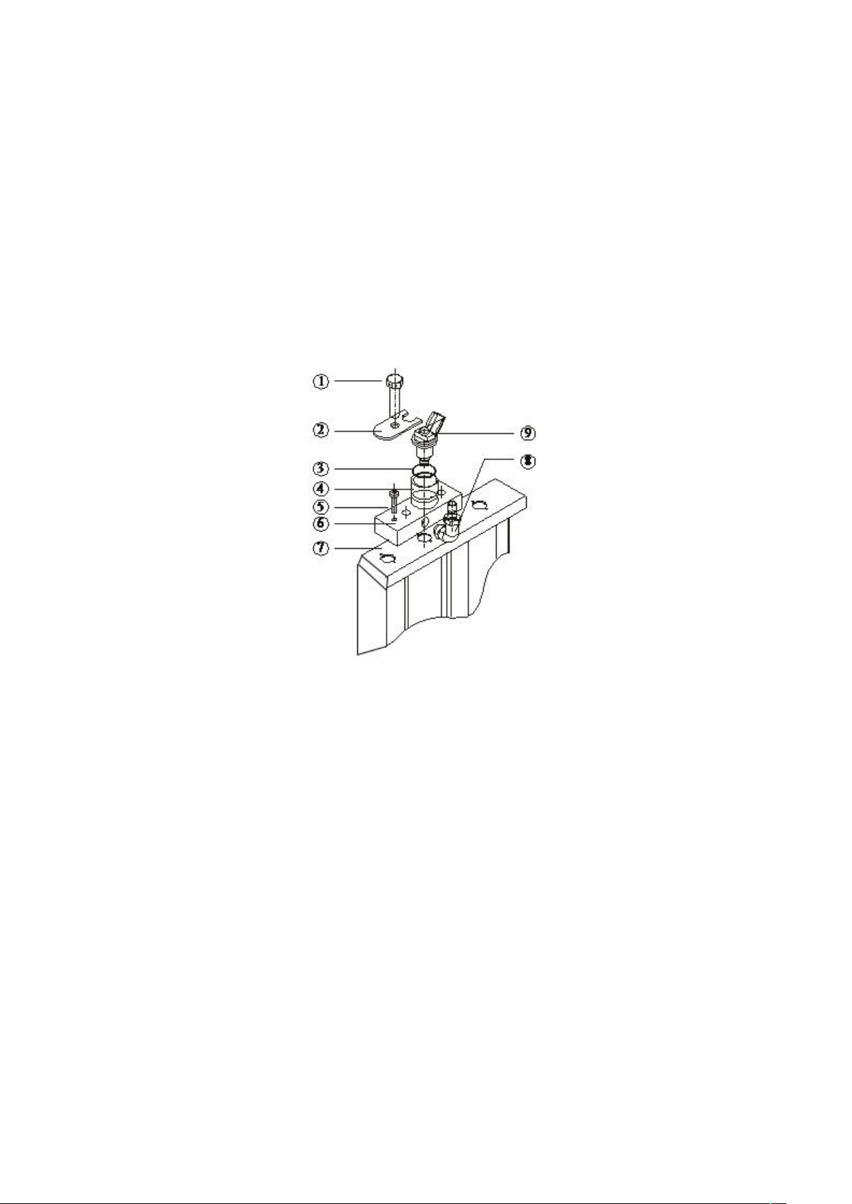
1
2
7
8
3
4
5
6
Lock nut7 Lock pole8
Oil outlet pipe
Top oil inlet connector
1
3
Oil rail
Injectors
2
4
Glass measuring cylinder
6
Upper plate seat
5
Top-in fuel injector installation diagram

10
Turn the pressure adjustment knob to adjust the pressure to
0.25 ~ 0.3MPa. (In the electronic injection system, the general
oil pressure works at 0.25 ~ 0.3MPa)
Press the up and down keys to select the appropriate pulse
width. (The system default is 3ms)
The working time gradually decreases. When it is 0, the system
automatically stops.
●
●
●
NOTE
The fuel pressure, working time and pulse width are automati-
cally set by the system. The time system defaults to 10s as a
cycle period, and the user does not need to set it separately.
The system will automatically and continuously cycle three
times to simulate the working condition and fuel injection
volume of the fuel injector when the engine is accelerating
uniformly.
03 Medium Speed Test
Select “03 Medium Speed Test”.
Press the start button.
The rest of the operation steps are consistent with item 02.
●
●
●
04 High Speed Test
Select “04 High Speed Test”.
Press the start button.
The rest of the operation steps are consistent with item 02.
●
●
●
05 Accelerating Test
Select “05 Accelerating Test”.
Press the start button.
●
●
06 Variable Speed Test
Select “06 Variable Speed Test”.
Press the start button.
●
●

11
NOTE
The pulse width system defaults to 3ms, no need to set it
again.
Whether the fuel injection nozzle is dripping and leaking when
the simulated oil pressure is 0.3Mpa.
NOTE
The fuel pressure, working time and pulse width are automati-
cally set by the system. The time system defaults to a cycle of
10s, and the user does not need to set it separately.
The system will automatically and continuously cycle three
times to simulate the working condition and fuel injection
volume of the fuel injector when the engine is idling, medium
speed, and high speed.
07 Leakage Test
Select “07 Leak Test”.
Press the working time up and down buttons to set the time.
(Generally set to 1 minute)
The rest of the operation steps are consistent with item 02.
●
Select “09 Medium Spray Volume”.
The rest of the operation steps are consistent with item 08.
●
●
09 Medium Speed Spray Volume Test
●
●
DESCRIPTION
Simulate the working conditions and fuel injection volume of
the engine when the fuel injection nozzle works for a certain
number of times when the engine is idling.
08 Idle Speed Spray Volume Test
Press the item selection up and down keys to select the “08
Idle fuel injecting amount test” item.
The remaining operation steps are consistent with item 02.
●
●

12
NOTE
Flow Balance Test
The flow balance test shall be carried out at different speeds.
When the liquid level in the measuring cylinder is 2/3 of the
measuring cylinder, pause or stop work to observe the balance
of the fuel injection volume. The deviation of the fuel injection
volume of all fuel injection nozzles on a vehicle should not
exceed 2%. Or refer to the relevant technical manual of the fuel
injector to judge the flow balance of the fuel injector.
Observation of Fuel Injection Shape
Observe whether the fuel injection shapes and angles of all
fuel injection nozzles on the same car are uniform at various
speeds. At the same time, you can adjust the opening pulse
width of the fuel injection nozzle to check whether the
minimum opening pulse width of the fuel injection nozzle is
consistent.
Leak Detection Test
The leak detection test is to detect the tightness of the injector
needle valve under the high pressure of the system. (Observe
the tightness of the fuel injector, generally there should be no
leakage within one minute)
10 High Speed Spray Volume Test
Select “10 High Spray Volume”.
The rest of the operation steps are consistent with item 08.
●
●
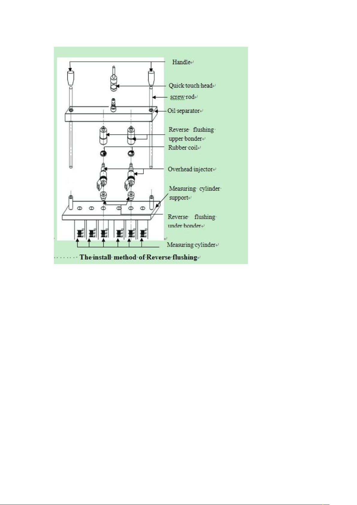
11 Reverse Flush Test
Press the item selection up and down keys to select “11
Reverse Flush”, and install the injectors in the opposite direc-
tion for cleaning.
●
12 No-disassembly Cleaning
Please connect to various special parts that can clean the
combustion chamber or throttle.
●
13 Unit Info
Display the product number and date of manufacture of the
device.
●

13
STORAGE AND MAINTENANCE
Storage
Turn off the power and unplug the power plug.
Put all connectors back into the accessory box for storage.
Drain the ultrasonic cleaning agent. Wipe the equipment clean
with a dry soft cloth.
If the machine needs to be stored for a long time, discharge the
testing agent into a bottle and seal it.
●
Replacement of Test Agent
When the test agent is used for a period of time, a lot of impuri-
ties will accumulate, and the agent containing dirt cannot be
used, otherwise it will easily block the fuel injector. When
replacing the agent, first open the testing agent drain valve to
empty the tank, and then inject a little testing agent to clean the
interior of the tank. After cleaning, drain the fuel tank again and
then pour 1L of new testing agent into the tank.
Fuse Replacement
There is a square box marked with a fuse on the power socket
on the left side of the device, and the fuse can be seen by
opening the box. If it is blown, replace it with a new one.
●
●
●
●
●

14
Be careful not to rub the product against rough surfaces or
wear the product, especially the sheet metal housing.
Please regularly check the product parts that need to be
tightened and connected. If found loose, please tighten it in
time to ensure the safe operation of the equipment. The exter-
nal and internal parts of the equipment in contact with various
chemical media should be frequently treated with anti-corrosion
treatment such as rust removal and painting to improve the
corrosion resistance of the equipment and extend its service
life.
Comply with the safe operating procedures and do not
overload the equipment. The safety guards of the products
are complete and reliable.
Unsafe factors are to be eliminated in time. The circuit part
should be checked thoroughly and the aging wires should be
replaced in time.
Adjust the clearance of various parts and replace worn
(broken) parts. Avoid contact with corrosive liquids.
When not in use, please store the product in a dry place. Do
not store the product in hot, humid, or non-ventilated places.
Our products are made of long-lasting and durable materials, and
we insist on perfect production process. Each product leaves the
factory after 35 procedures and 12 times of testing and inspec-
tion work, which ensures that each product has excellent quality
and performance.
To maintain the performance and appearance of the product, it is
recommended that the following product care guidelines be read
carefully:
●
●
●
●
●
●
MAINTENANCE SERVICE
Maintenance

15
WARRANTY
The repair or replacement of products is determined by the
actual breakdown situation of product.
It is guaranteed that AUTOOL will use brand new component,
accessory or device in terms of repair or replacement.
If the product fails within 90 days after the customer receives
it, the buyer should provide both video and picture, and we will
bear the shipping cost and provide the accessories for the
customer to replace it free of charge. While the product is
received for more than 90 days, the customer will bear the
appropriate cost and we will provide the parts to the customer
for replacement free of charge.
The product is not purchased through official or authorized
channels.
The product breakdown because the user does not follow
product instructions to use or maintain the product.
From the date of receipt, we provide a three-year warranty for the
main unit and all the accessories included are covered by a
one-year warranty.
We AUTOOL pride ourselves on superb design and excellent
service. It would be our pleasure to provide you with any further
support or services.
All information, illustrations, and specifications contained in this
manual, AUTOOL resumes the right of modify this manual and the
machine itself with no prior notice. The physical appearance and
color may differ from what is shown in the manual, please refer to
the actual product. Every effort has been made to make all
descriptions in the book accurate, but inevitably there are still
inaccuracies, if in doubt, please contact your dealer or AUTOOL
after-service centre, we are not responsible for any consequences
arising from misunderstandings.
●
●
●
●
●
These conditions below shall not be in warranty range
Warranty
access
Disclaimer

16
If you are an AUTOOL user and are not satisfied with the
AUTOOL products purchased from the online authorized
shopping platform and offline authorized dealers, you can
return the products within seven days from the date of receipt;
or you may exchange it for another product of the same value
within 30 days from the date of delivery.
Returned and exchanged products must be in fully saleable
condition with documentation of the relevant bill of sale, all
relevant accessories and original packaging.
AUTOOL will inspect the returned items to ensure that they
are in good condition and eligible. Any item that does not pass
inspection will be returned to you and you will not receive a
refund for the item.
You can exchange the product through the customer service
center or AUTOOL authorized distributors; the policy of return
and exchange is to return the product from where it was
purchased. If there are difficulties or problems with your return
or exchange, please contact AUTOOL Customer Service.
●
●
●
●
RETURN & EXCHANGE SERVICE
Return &
Exchange
China
Oversea Zone
E-mail
Facebook
YouTube
400-032-0988
+86 0755 23304822
aftersale@autooltech.com
https://www.facebook.com/autool.vip
https://www.youtube.com/c/autooltech

17
TABLA DE CONTENIDOS
Derecho de autor................................................................................................ 18
Derecho de Autor............................................................................................ 18
Marca Comercial............................................................................................. 18
Precaución .......................................................................................................... 19
Advertencia ..................................................................................................... 19
Introducción del producto................................................................................. 20
Resumen......................................................................................................... 20
Funciones principales ..................................................................................... 20
Carácterísticas principales.............................................................................. 20
Entorno de trabajo........................................................................................... 21
Parámetros técnicos ....................................................................................... 21
Estructura del producto..................................................................................... 22
Diagrama de Estructura .................................................................................. 22
Diagrama del panel de operaciones ............................................................... 23
Proceso de operación........................................................................................ 25
Limpieza ultrasónica ....................................................................................... 25
Diagnóstico del inyector.................................................................................. 26
Almacenamiento y manteimiento ..................................................................... 32
Almacenamiento ............................................................................................. 32
Servicio de mantenimiento................................................................................ 33
Mantenimiento................................................................................................. 33
Garantía............................................................................................................... 34
Acceso a la garantía ....................................................................................... 34
Descargo de responsabilidad.......................................................................... 34
Servicio de devolución y cambio...................................................................... 35
Devolución & Cambio...................................................................................... 35

18
DERECHO DE AUTOR
Derecho
de Autor
Marca
Comercial
Manual son marcas comerciales, marcas registradas, marcas de servicio,
nombres de dominio, logotipos, nombres de empresas o son de otra
manera la propiedad de AUTOOL o sus sucursales. En los países donde
cualquiera de las marcas comerciales, marcas de servicio, nombres de
dominio, logotipos y nombres de empresas de AUTOOL no están registra-
dos, AUTOOL reclama otros derechos asociados a las marcas comercia-
les no registradas, marcas de servicio, nombres de dominio, logotipos y
nombres de empresas. Otros productos o nombres de empresas a los
que se hace referencia en este manual pueden ser marcas comerciales
de sus respectivos propietarios. Usted no puede utilizar ninguna marca
comercial, marca de servicio, nombre de dominio, logotipo o nombre de la
empresa de AUTOOL o de terceros sin el permiso del propietario de la
marca comercial aplicable, marca de servicio, nombre de dominio,
logotipo o nombre de la empresa. Usted puede ponerse en contacto con
AUTOOL consultando el sitio web https://www.au- tooltech.com, o escrib-
iendo a aftersale@autooltech.com, para solicitar el permiso por escrito
para utilizar los materiales en este manual para fines o para todas las
demás cuestiones relacionadas con este manual.
●
●
●
●
Todos los derechos reservados por AUTOOL TECH. CO., LTD. (en
adelante, “AUTOOL”), ninguna parte de esta publicación puede ser
reproducida, guardada en cualquier forma (electrónica, mecánica,
fotocopiada, grabada u otra forma) por ninguna parte o empresa sin el
permiso previo por escrito de AUTOOL. El contenido en este
documento está diseñado solo para el uso de esta unidad. AUTOOL
no es responsable de ningún uso de esta información aplicada a otras
unidades.
Ni AUTOOL ni sus sucursales serán responsables ante el comprador
de esta unidad o terceros por daños, pérdidas, costos o gastos
incurridos por el comprador o terceros como resultado de: accidente,
mal uso o abuso de esta unidad, o modificaciones no autorizadas,
reparaciones o alteraciones de esta unidad, o incumplimiento estricto
de las instrucciones de operación y mantenimiento de AUTOOL.
AUTOOL no será responsable de ningún daño o problema que surja
del uso de cualquier accesorio o cualquier producto consumible que
no sean los productos originales o aprobados por AUTOOL.
Otros nombres de productos utilizados en este documento son solo
para identificar el uso de la unidad y sus derechos de autores de
marcas comerciales permanecen a sus respectivos propietarios.
AUTOOL renuncia a todos y cada uno de los derechos de autor sobre
esas marcas.
19
PRECAUCIÓN
Advertencia
Dado que el dispositivo de prueba es parte del vidrio de
cuarzo, es fácil de romper, por lo que no coloque otros objetos
alrededor del equipo para evitar golpes y roturas.
Si no hay una pantalla digital después del encendido, por favor
compruebe si la fuente de alimentación está proporcionada; si
está proporcionada, compruebe si el enchufe está conectado
firmemente o si el fusible está quemado. Si no está roto y el
interruptor aún no sirve después de presionar el interruptor
varias veces de forma intermitente, comuníquese con el
fabricante y no debe desmontarlo por sí mismo, de lo contrario,
nuestra compañía no proporcionará ninguna garantía.
Cuando no se agrega ningún agente de limpieza al tanque
ultrasónico, está estrictamente prohibido abrir el artículo de
limpieza ultrasónica para evitar daños al sistema ultrasónico.
Cada vez que se cambia la solución de prueba, debe limpiarse
y luego se debe agregar 1L de nueva solución de prueba.
El uso de un agente de prueba no calificado causará corrosión
de la bomba de aceite, la tubería de suministro de petróleo y la
falla del manómetro.
El uso de otro agente de limpieza y agente de prueba hará que
el recubrimiento de la superficie del equipo se despegue.
Está estrictamente prohibido usar queroseno, gasolina u otro
agente de prueba y agentes de limpieza como agente de
prueba y agentes de limpieza para esta máquina. De lo
contrario, el anillo “O” y las piezas de goma de la tubería en el
equipo se dañarán y causará fugas.
El agente de limpieza y el agente de prueba no deben
mezclarse.
Antes de utilizar el instrumento, lea atentamente este manual
para un funcionamiento adecuado.

20
El equipo de diagnóstico y limpieza del inyector de combustible es
un producto mecatrónico que combina la tecnología de limpieza
ultrasónica y la tecnología de limpieza y detección de control de
aceite cerrado a presión de aceite microinformática. Este produc-
to simula varias condiciones de funcionamiento del motor, y
limpia e inspecciona los inyectores de combustible de varios
automóviles y motocicletas. Este equipo es el equipo necesario y
preferido para la industria de reparación y mantenimiento de
automóviles y motocicletas, los departamentos de enseñanza y
capacitación y de la investigación.
INTRODUCCIÓN DEL PRODUCTO
Resumen
Funciones
principales
Limpieza ultrasónica:
La limpieza ultrasónica se puede realizar en uno o varios
inyectores al mismo tiempo, lo que puede eliminar los acceso-
rios y los bloqueos internos en los inyectores.
Detección de uniformidad:
Detectar la uniformidad del volumen de inyección de cada
inyector.
Observación de la atomización:
Utilizando la luz de fondo, puede observar la situación de atom-
ización de la boquilla de una manera completa y cuidadosa.
Prueba de estanqueidad:
Puede detectar la estanqueidad y el goteo del inyector de
combustible a alta presión.
Volumen de inyección de combustible:
Puede detectar el volumen de inyección de combustible de la
boquilla de inyección de combustible en condiciones de trabajo
específicas (como el mismo tiempo y el mismo número de
veces).
●
●
●
●
●
Utilizando tecnología de limpieza ultrasónica potente, fuerte
capacidad de limpieza.
Utilizando tecnología de control de regulación de presión
electrónica, presión de aceite estable y amplio rango ajustable.
●
●
Carac-
terísticas
principales
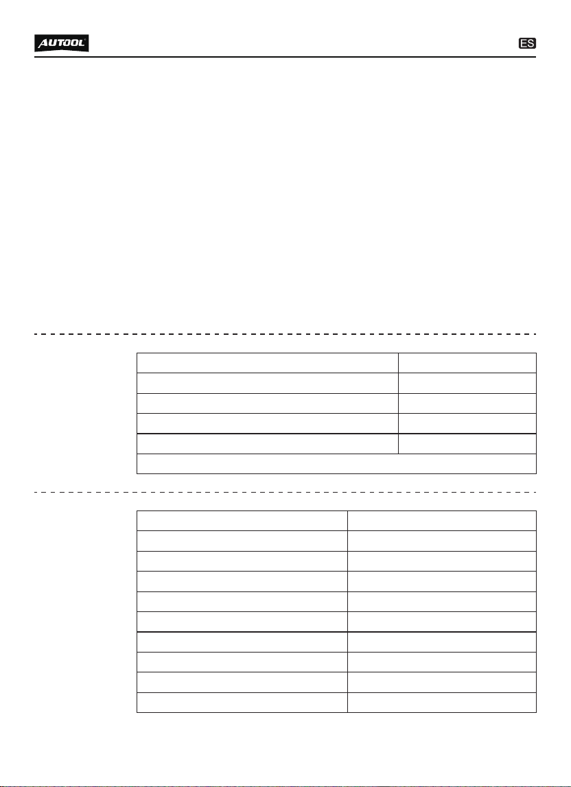
Fuente de alimentación
Frecuencia
Humedad relativa
Temperatura del entorno
AC 110/220V ±10%
50HZ ±0.5
<85%
0°C~+40°C
Intensidad del campo magnético externo
No se permiten llamas abiertas alrededor
<400A/m
21
Entorno de
trabajo
Rango de rotación
Ancho de Pulso PWM
Hora
0~7500RPM
0~20ms
0~10min
Frecuencia de limpieza
40kHz
Volumen del cilindro
Tiempos de inyección
Presión del sistema
Potencia de limpieza ultrasónica
140ml
0~9900veces, paso 100ms
0~0.6Mpa
28KHZ ±0.5KHZ
Tamaño del producto
300*220*320mm
Parámetros
técnicos
Utilice una bomba de aceite de alta calidad para garantizar un
uso estable a largo plazo.
El uso de una pantalla de tubo digital de alta definición hace
que la operación sea clara y fácil de aprender.
El nivel de líquido del tanque de aceite se muestra visualmente
y el líquido de detección se puede reciclar.
Luz de fondo brillante, puede ver claramente las diversas
situaciones del inyector de combustible cuando está funcionando.
Tiene juntas compuestas reemplazables adecuadas para una
variedad de tipos de vehículos.
Dentro del rango de ajuste permitido, el tiempo de prueba, la
frecuencia de trabajo, los tiempos de inyección de combusti-
ble, el período de conmutación más corto, etc. del inyector de
combustible se pueden ajustar arbitrariamente.
●
●
●
●
●
●
Capacidad del tanque
2500ml
22
ESTRUCTURA DEL PRODUCTO
Diagrama de
Estructura
Panel de control
Manómetro
7
9
Tubería de salida de aceite
Interruptor de encendido
8
10
Toma de corriente
11
Perno de bloqueo
Tubería de aceite
1
3
Tuerca de bloqueo
Conector superior de
entrada de aceite
2
4
Manilla para drenar el aceite
6
Cable de señal
12
Cilindro medidor de vidrio
5
15
14
13
10
7
11
12
6
5
2
1
4
3
9
8
23
Diagrama del
panel de
operaciones
Tanque de limpieza
ultrasónica
Nivel de líquido del
agente de prueba
13
15
Válvula para drenar
el agente de limpieza
14
Ancho de pulso / Ventana de función:
Mostrar el ítem de función seleccionado cuando se seleccione
la función y mostrar el ancho de pulso del inyector cuando
trabaje.
Ventana de tiempo:
Mostrar el tiempo de trabajo del inyector de combustible y el
número de inyección de combustible.
Botón de ajuste de ancho de pulso:
Ajustar el ancho de pulso del inyector cuando trabaje.
Presionar hacia arriba para aumentar el ancho de pulso de
trabajo del inyector al limpiar el inyector.
Presionar hacia abajo para limpiar el inyector para reducir
el ancho de pulso de trabajo del inyector.
Botón de ajuste de tiempo / hora:
Ajustar el tiempo de trabajo del inyector y el número de inyec-
ciones.
Presionar hacia arriba para aumentar el tiempo de trabajo
●
●
●
●
●
●
●

24
del inyector / el número de inyecciones.
Presionar hacia abajo para reducir el tiempo de trabajo del
inyector número de inyecciones.
Botón de inicio:
Pulsar para ejecutar el ítem de trabajo seleccionado.
Botón de pausa:
Pausar temporalmente el ítem de trabajo seleccionado
después de presionarlo.
Botón de detener:
Detener el ítem de trabajo seleccionado y volver al ítem de
trabajo seleccionado.
Botón de selección de funciones:
Seleccionar el ítem de trabajo.
Presionar hacia arriba para seleccionar el ítem de trabajo.
Presionar hacia abajo para seleccionar el ítem de trabajo.
Perilla de ajuste de presión:
Ajustar el cambio de presión.
Girar en el sentido de las agujas del reloj para aumentar el
valor de presión.
Girar en sentido contrario a las agujas del reloj para reducir
la presión.
●
●
●
●
●
●
●
●
●
●

25
PROCESO DE OPERACIÓN
Limpieza
ultrasónica
La limpieza ultrasónica consiste en utilizar las ondas de choque
penetrantes y de cavitación generadas cuando las ondas ultrasóni-
cas se propagan en el medio, y limpiar poderosamente los objetos
con formas complejas, cavidades y poros con el fin de eliminar por
completo los depósitos de carbono persistentes en el inyector de
combustible.
Preparación
Retire el inyector de combustible del vehículo y compruebe si
su sello de goma está dañado. Si está dañado, debe reempla-
zarse a tiempo antes de la prueba de limpieza para evitar
fugas durante la prueba. Luego coloque la boquilla de inyec-
ción de combustible en el agente de limpieza, retire completa-
mente la grasa externa y límpiela con un paño suave.
Encienda la alimentación y encienda el interruptor de encendi-
do en el lateral de la unidad principal
Coloque el soporte de limpieza de los accesorios en el tanque
de limpieza ultrasónica, y coloque el inyector de combustible
limpiado en el agujero de posicionamiento del soporte de
limpieza del tanque de ultrasónico.
●
●
●
Método y Pasos
Agregue una cantidad adecuada de agente de limpieza al
tanque ultrasónico y extienda el agente de limpieza sobre la
parte inferior del soporte de limpieza.
Inserte los enchufes de los cables de la unidad en los
enchufes del inyector a su vez. (Los inyectores de combustible
especiales deben conectarse con un cable adaptador)
Presione los botones de selección de ítems hacia arriba y
hacia abajo para seleccionar el ítem “01 Limpieza ultrasónica”
y, a continuación, presione los botones de tiempo de trabajo
hacia arriba y hacia abajo para establecer la hora. (El sistema
predeterminado es 10 minutos, si necesita modificar el tiempo,
puede presionar los botones hacia arriba y abajo para cambiar)
Presione el botón de inicio y encienda el interruptor de limpie-
za ultrasónico en el lado del dispositivo para comenzar a
●
●
●
●
26
NOTA
Durante el proceso de limpieza, puede escuchar el sonido
vibratorio intermitente (aproximadamente 5 segundos) cuando
saca el inyector de combustible y se lo pone en el oído, así que
pueda juzgar si el inyector de combustible está funcionando
normalmente.
La limpieza ultrasónica está estrictamente prohibida cuando
no hay un agente de limpieza en el tanque ultrasónico para
evitar daños en el equipo.
Solo el agente de limpieza ultrasónico calificado para la
limpieza de la boquilla de inyección de combustible se puede
agregar al tanque ultrasónico, y no se pueden reemplazar de
otro agente, de lo contrario, cualquier mal funcionamiento y
daños causados no estarán cubiertos por la garantía.
limpiar. Cuando trabaje, puede presionar el botón de pausa
para suspender el trabajo o presionar el botón de detener para
salir.
Durante el proceso de limpieza, el interruptor de calentamien-
to en el lado del equipo se puede encender para mejorar el
efecto de limpieza.
El tiempo de trabajo disminuye gradualmente. Cuando es 0, el
sistema se detiene automáticamente.
Saque la boquilla de inyección de combustible del tanque
ultrasónico, limpie el líquido de limpieza en ella con un paño
suave y prepárese para el siguiente trabajo.
●
●
●
Diagnóstico
del inyector
Esta función consiste en detectar la atomización, el goteo, el
bloqueo, el ángulo de inyección de combustible de los inyectores
de combustible y el tamaño y equilibrio de la inyección de combus-
tible de cada inyector de combustible a diferentes velocidades.
Preparación
Confirme que la manilla de drenar el aceite esté abierta, use el
embudo en los accesorios para agregar el líquido de prueba al
equipo a través de la ventana de vidrio y preste atención para
controlar el caudal durante la adición para evitar el desbor-
damiento.
●
27
Seleccione el conector de entrada de aceite superior de los
accesorios e instálelo en el separador de aceite.
Instale el inyector de combustible en la dirección hacia adelan-
te (Aplique un poco de grasa en el anillo “O” del inyector de
combustible)
Coloque el extremo horizontal del separador de aceite y el inyec-
tor de combustible en el asiento de la placa superior, y apriete
los dos extremos con la varilla de bloqueo. Listo para probar.
●
●
●
●
●
Agregue 1 frasco (aproximadamente 1000 ml) de agente de
prueba cada vez.
Instale el inyector de combustible.
Métodos y pasos
02 Prueba de velocidad de ralentí
Confirme que el inyector que se va a probar se ha instalado
correctamente y que el cable de señal se ha enchufado.
Seleccione “02 Prueba de velocidad de ralentí”.
●
●
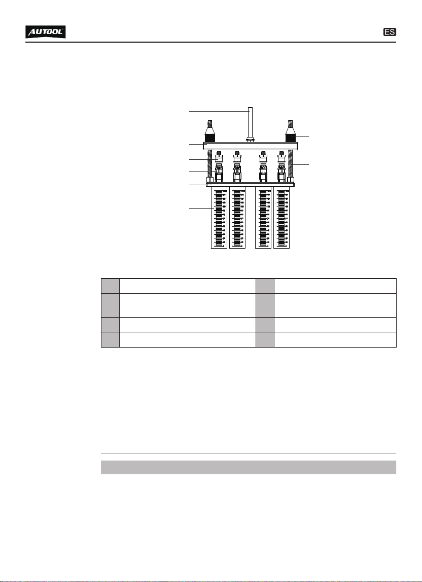
1
2
7
8
3
4
5
6
Tuerca de bloqueo7 Perno de bloqueo8
Tubería de salida de aceite
Conector superior de
entrada de aceite
1
3
Tubería de aceite
Inyectores
2
4
Cilindro medidor de vidrio
6
Asiento de la placa superior
5
Diagrama de instalación del inyector de combustible
de entrada superior
28
Presione los botones de tiempo de trabajo hacia arriba y hacia
abajo para establecer la hora. (Generalmente establecido en 2
minutos)
Presione el botón de inicio para comenzar a trabajar.
Gire la perilla de ajuste de presión para ajustar la presión a
0.25 ~ 0.3MPa. (En el sistema de inyección electrónica, la
presión general de aceite funciona a 0.25 ~ 0.3MPa)
Presione las teclas arriba y abajo para seleccionar el ancho de
pulso apropiado. (El valor predeterminado del sistema es 3ms)
El tiempo de trabajo disminuye gradualmente. Cuando es 0, el
sistema se detiene automáticamente.
●
●
●
●
●
NOTA
La presión del combustible, el tiempo de trabajo y el ancho de
pulso se establecen automáticamente por el sistema. El
tiempo del sistema está preestablecido en 10 segundos como
un ciclo, y los usuarios pueden ajustarlo según sea necesario.
El sistema realizará automáticamente tres ciclos continuos
para simular el funcionamiento del inyector de combustible y la
cantidad de inyección de combustible durante la aceleración
uniforme.
03 Prueba de velocidad media
Seleccione “03 Prueba de velocidad media”.
Pulse el botón de inicio.
El resto de los pasos de operación son consistentes con el
paso 02.
●
●
●
04 Prueba de alta velocidad
Seleccione “04 Prueba de alta velocidad”.
Pulse el botón de inicio.
El resto de los pasos de operación son consistentes con el
paso 02.
●
●
●
05 Prueba de aceleración
Utilice las teclas de flecha arriba y abajo para seleccionar
“Ítem 05 - Prueba de Aceleración”.
Presione la tecla de Inicio para comenzar la prueba.
●
●
06 Prueba de velocidad variable
Utilice las teclas de flecha arriba y abajo para seleccionar
“Ítem 06 - Prueba de Velocidad Variable”.
Presione la tecla de Inicio para comenzar la prueba.
●
●
29
NOTA
El sistema de ancho de pulso predeterminado es de 3 ms, sin
necesidad de volver a configurarlo.
Si la inyección de combustible no está goteando y goteando
cuando la presión de aceite simulada es de 0.3Mpa.
NOTA
La presión del combustible, el tiempo de trabajo y el ancho de
pulso se establecen automáticamente por el sistema. El
tiempo del sistema está preestablecido en 10 segundos como
un ciclo, y los usuarios no necesitan ajustarlo por separado.
El sistema realizará automáticamente tres ciclos continuos
para simular el funcionamiento del inyector de combustible y la
cantidad de inyección de combustible durante la aceleración
uniforme.
07 Prueba de fugas
Seleccione “07 Prueba de fugas”.
Presione los botones de tiempo de trabajo hacia arriba y hacia
abajo para establecer la hora. (Generalmente establecido en 1
minuto)
El resto de los pasos de operación son consistentes con el
paso 02.
●
●
●
08 Prueba de volumen de pulverización de velocidad de ralentí
●
●
Pulse las teclas de selección de ítems arriba y abajo para
seleccionar el ítem “08 Prueba de cantidad de inyección de
combustible al ralentí”.
Los restantes pasos de la operación son coherentes con el
ítem 02.

30
NOTA
10 Prueba de volumen de pulverización de alta velocidad
Seleccione “10 Volumen de pulverización de alta velocidad”.
El resto de los pasos de operación son consistentes con el
paso 08.
●
Seleccione “09 Volumen de pulverización de velocidad media”.
El resto de los pasos de operación son consistentes con el
paso 08.
●
●
●
09 Prueba de volumen de pulverización de velocidad media
DESCRIPCIÓN
Simule las condiciones de trabajo y el volumen de inyección
de combustible del motor cuando la boquilla de inyección de
combustible funcione durante un cierto número de veces
cuando el motor está al ralentí.
Uniformidad
Esto es para comprobar la uniformidad llevada a cabo a varias
rpm. Cuando el nivel del líquido de prueba está a 2/3 del tubo
de ensayo, por favor, haga una pausa o detenga la máquina
para observar la uniformidad de la cantidad de inyección. La
diferencia de inyección de todos los inyectores en un vehículo
debe mantenerse dentro del 2%. O consulte el manual técnico
correspondiente del inyector de combustible para determinar a
uniformidad de la cantidad de inyección.
Observar la forma de los inyectores
Observe si las formas y los ángulos de inyección de todos los
inyectores de combustible del mismo vehículo son idénticos a
distintas velocidades. Al mismo tiempo, puede ajustar la
anchura del pulso de inyección de los inyectores de combusti-
ble para comparar si la anchura mínima del pulso de inyección
entre los inyectores de combustible es consistente.
Prueba de estanqueidad
La prueba de estanqueidad consiste en inspeccionar las
condiciones de sellado de la válvula de aguja del inyector bajo
la presión del sistema. (Observar la estanqueidad de los
inyectores de combustible, generalmente, no debe haber
fugas en un minuto).

31
12 ítems de limpieza totalmente automática
Por favor, conecte a varias piezas especiales que pueden
limpiar la cámara de combustión o el acelerador.
●
Pulse las teclas de selección de ítems hacia arriba y hacia
abajo para seleccionar “11 Reverse Flush”, e instale los inyec-
tores en la dirección opuesta para su limpieza.
●
11 Prueba de lavado inverso
13 Info de Unidad
Mostrar el número de producto y la fecha de fabricación del
dispositivo.
●

32
ALMACENAMIENTO Y MANTENIMIENTO
Apague la alimentación y desenchufe el enchufe de
alimentación.
Vuelva a colocar todos los conectores en la caja de accesorios
para su almacenamiento.
Escurra el agente de limpieza ultrasónico. Limpie el equipo
con un paño suave y seco.
Si la máquina necesita almacenarse durante mucho tiempo,
descargue el agente de prueba en una botella y séllelo.
●
●
●
●
●
●
Almacén
amiento
Reemplazo del agente de prueba
Las impurezas pueden acumularse en el líquido de prueba
después de ser utilizado durante un período de tiempo. No
utilice líquido de prueba contaminado, de lo contrario, los
inyectores y las bombas de combustible pueden bloquearse.
Vacíe el líquido de prueba retirando el indicador de nivel
situado a la izquierda de la unidad principal. Es mejor limpiar el
depósito de combustible con un poco de líquido de prueba
antes de llenar el depósito con el nuevo líquido. Después de la
limpieza, vuelva a cerrar la válvula del líquido de prueba y
vierta el nuevo líquido de prueba.
Reemplazo de fusibles
Hay una caja cuadrada marcada con un fusible en la toma de
corriente en el lado izquierdo del dispositivo, y el fusible se
puede ver abriendo la caja. Si está quemado, reemplácelo por
uno nuevo.

33
Tenga cuidado de no frotar el producto contra superficies
ásperas o desgastar el producto, especialmente la carcasa de
chapa
Compruebe regularmente las piezas del producto que deben
apretarse y conectarse. Si se encuentra suelto, apriete a
tiempo para garantizar el funcionamiento seguro del equipo.
Las partes externas e internas del equipo en contacto con
diversos medios químicos deben tratarse con frecuencia con
tratamiento anticorrosión, como la eliminación de óxido y la
pintura, para mejorar la resistencia a la corrosión del equipo y
prolongar su vida útil.
Cumplir con los procedimientos de operación segura y no
sobrecargar el equipo. Los protectores de seguridad de los
productos son completos y fiables.
Los factores inseguros deben eliminarse a tiempo. La parte
del circuito debe revisarse a fondo y los cables envejecidos
deben reemplazarse a tiempo.
Ajuste el espacio libre de varias piezas y reemplace las
piezas desgastadas (rotas). Evite el contacto con líquidos
corrosivos.
Cuando no esté en uso, guarde el producto en un lugar seco.
No guarde el producto en lugares cálidos, húmedos o sin
ventilación.
Nuestros productos están hechos de materiales duraderos, e
insistimos en un proceso de producción perfecto. Cada producto
sale de la fábrica después de 35 procedimientos y 12 veces de
pruebas y trabajos de inspección, lo que garantiza que cada
producto tenga una excelente calidad y rendimiento.
Para mantener el rendimiento y la apariencia del producto, se
recomienda que se lean cuidadosamente las siguientes pautas
de cuidado del producto:
SERVICIO DE MANTENIMIENTO
Manten-
imiento
●
●
●
●
●
●

34
GARANTÍA
La reparación o sustitución de productos viene determinada
por la situación real de avería del producto.
Está garantizado que AUTOOL utilizará un nuevo componente,
accesorio o dispositivo en términos de reparación o reemplazo.
Si el producto falla dentro de los 90 días después de la recep-
ción del cliente, el comprador debe proporcionar tanto el
video como la imagen, y nosotros asumiremos los costos de
envío y proporcionaremos los accesorios para que el cliente
lo reemplace de forma gratuita. Mientras el producto ha sido
recibido más de 90 días, el cliente cubrirá el costo apropiado
y proporcionaremos las piezas al cliente para su reemplazo
de forma gratuita.
El producto no se compra a través de canales oficiales o
autorizados.
El desglose del producto porque el usuario no sigue las
instrucciones del producto para usar o mantener el producto.
A partir de la fecha de recepción, ofrecemos una GARANTÍA de
3 años para la unidad principal y todos los accesorios incluidos
están cubiertos por una garantía de 1 año.
AUTOOL nos enorgullecemos de un excelente diseño y
excelente servicio. Sería un placer para nosotros proporcionarle
más apoyo o servicios.
Toda la información, ilustraciones y especificaciones contenidas
en este manual, AUTOOL se reserva el derecho de modificar
este manual y la propia máquina sin previo aviso. La apariencia
física y el color pueden diferir de lo que se muestra en el manual,
consulte el producto real. Se ha hecho todo lo posible para que
todas las descripciones en el libro sean precisas, pero inevita-
blemente hay inexactitudes, en caso de tener cualquier duda,
comuníquese con su distribuidor o centro de post servicio de
AUTOOL, no somos responsables de las consecuencias que
surjan de malentendidos.
●
●
●
●
●
Estas condiciones a continuación no estarán en el rango
Acceso a
la garantía
Descargo de
responsabili
dad
35
Si usted es un usuario de AUTOOL y no está satisfecho con
los productos AUTOOL comprados en la plataforma de
compras autorizada en línea y en los distribuidores autoriza-
dos fuera de línea, puede devolver los productos dentro de los
siete días a partir de la fecha de recepción; o puede cambiarlo
por otro producto del mismo valor dentro de los 30 días a
partir de la fecha de entrega.
Los productos devueltos y cambiados deben estar en condi-
ciones totalmente vendibles con la documentación de la
factura de venta correspondiente, todos los accesorios
relevantes y el embalaje original.
AUTOOL inspeccionará los artículos devueltos para asegu-
rarse de que están en buenas condiciones y son elegibles.
Cualquier artículo que no pase la inspección se le devolverá y
no recibirá un reembolso por el artículo.
Puede cambiar el producto a través del centro de atención al
cliente o distribuidores autorizados de AUTOOL; la política de
devolución y cambio es devolver el producto desde donde se
compró. Si hay dificultades o problemas con su devolución o
cambio, póngase en contacto con el servicio de atención al
cliente de AUTOOL.
SERVICIO DE DEVOLUCIÓN Y CAMBIO
Devolución &
Cambio
China
Otros países
Correo electrónico
Facebook
YouTube
400-032-0988
+86 0755 23304822
aftersale@autooltech.com
https://www.facebook.com/autool.vip
https://www.youtube.com/c/autooltech
●
●
●
●

36
目 录
版权信息.............................................................................................................. 38
版权................................................................................................................. 38
注册商标.......................................................................................................... 38
注意事项 ............................................................................................................. 39
警告................................................................................................................. 39
产品简介.............................................................................................................. 41
产品介绍.......................................................................................................... 41
主要功能.......................................................................................................... 41
主要特点.......................................................................................................... 41
工作环境 .......................................................................................................... 42
技术指标.......................................................................................................... 42
产品结构 ............................................................................................................. 43
整机结构.......................................................................................................... 43
控制面板说明 .................................................................................................. 44
安装与连接 ......................................................................................................... 45
简单安装 .......................................................................................................... 45
喷油嘴离车检测一般操作程序......................................................................... 45
准备工作 .......................................................................................................... 45
清洗与测试顺序............................................................................................... 46
操作后的整理 .................................................................................................. 46
操作过程说明 ..................................................................................................... 47
超声波清洗 ...................................................................................................... 47
测试功能.......................................................................................................... 48
维护 ..................................................................................................................... 52
整理................................................................................................................. 52
维护................................................................................................................. 52
维修保养服务..................................................................................................... 53
维修保养.......................................................................................................... 53

37
保修服务 ............................................................................................................. 54
保修方式.......................................................................................................... 54
声明 ................................................................................................................. 54
退换货服务......................................................................................................... 55
退换货 ............................................................................................................. 55
38
版权信息
偶然公司已在中国及海外若干国家进行了商标注册,其标志为
。本手册所提及之偶然公司其它商标、服务标志、域名、图
标、公司名称均属偶然及其下属公司之产权。在偶然公司之商标、服
务标志、域名、图标、公司名称还未注册之国家,偶然公司声明其对
未注册商标、服务标志、域名、图标、公司名称之所有权。本手册所
提及之其它产品及公司名称的商标仍属于原注册公司所有。在未得
到拥有人的书面同意之前,任何人不得使用偶然公司或所提及的其
它公司之商标、服务标志、域名、图标、公司名称。
您可以访问偶然网址:www.autooltech.com,或发送邮件至:
aftersale@autooltech.com,与偶然公司进行联系,征得其手册使
用权之书面同意。
版权所有!未征得深圳市偶然科技有限公司的书面同意,任何公
司或个人不得以任何形式(电子、机械、影印、录制或其他形式)
对本说明书进行复制和备份。本手册专为偶然公司产品的使用
而计,对于将之用于指导其他设备操作而导致的各种后果,本公
司不承担任何责任。
因使用者个人或第三方的意外事故,滥用、误用该设备,擅自更
改,或修理该设备,或未按偶然公司的操作与保养要求而导致设
备损坏、遗失所产生的费用及开支等,偶然公司及其分支机构不
承担任何责任。
正式声明: 本说明书所提及之其他产品名称,目的在于说明该设
备如何使用,其注册商标所有权仍属原公司。
本设备供专业技术人员或维修人员使用。
●
●
●
●
版权
注册商标
39
注意事项
在使用仪器之前,请仔细阅读本说明书,以便正确操作。
触摸设备或发动机发热部位时要小心。
如电源线有破损请不要开机使用,设备摔落或受损时请在专业人
员检查后才可使用。
不要让电源线悬挂在桌边、椅边、柜台边,也不要接触热的部分
或正在转动的风扇页。
如需扩充的电源线,电源线的等级要大于等于原设备电源线。比
设备原电源线等级差的电源线会过热。
不使用设备时不要连接电源线插头。不要通过拉电源线来拔插
头,应用手将插头取下。
存放设备前应让设备完全冷却,并且将线松软的绕好。
本仪器所选用的清洗液系易燃、弱挥发性液体,在清洗过程中严
禁烟火。
仪器应放在无阳光直射且通风良好的房间内,并张贴“严禁烟火
和“易燃品危险警告”标志。
操作者的头发、衣服、手指或身体其他部位应远离设备运转部位
为了防止受电击,不要在潮湿的部位接触工作中的设备或在雨中
操作设备。
请按手册中的方法操作设备。使用生产商推荐的附件。
在超声波清洗池未加超声波清洗液的情况下,严禁打开超声波
系统,否则容易损坏超声波设备。
设备机壳必须可靠接地。
汽车尾气中含有多种有毒有害气体(如一氧化碳、碳化氢、氮氧
化物等),测试时要将其引到室外并保持室内良好通风。
汽车发动机排气管和水箱等部件温度较高,勿碰,以防灼伤。
重要的安全说明:
警告
”
。

40
免拆清洗时,被清洗车辆要拉好手制动,并将变速器置于空档,
同时挡好前轮。
操作时要戴安全防护眼镜。日常用的眼镜不是安全的眼镜。
断开有压力的燃油管接头时要用毛巾捂住接头,以防燃油窜出
伤人及引起火灾。
本设备主机使用检测液,免拆清洗使用清洗液。超声波清洗使用
专用的超声波清洗液,若没有,可以用本设备配备的清洗液代替
由于测试装置部分为石英玻璃,易破碎,因此不要在设备周围放
置其它物品,以免磕碰造成破碎。
通电后若无数字显示(可能存在数秒延迟),请检查电源是否有
电; 如有,请检查插头是否接牢,或者检查保险管是否熔断。如没
断,且断续按动开关几次仍无效,请与当地经销商联系,切不可
自 行 拆 开 ,否 则 我 公 司 将 不 予 保 修 。
在超声槽内没有添加清洗液时,严禁打开超声波清洗项目,以免
空打造成超声系统损坏。
测试液每次更换时,必须全部排空,然后再添加1000ml测试液
使用不合格的测试液将造成泵浦、供油管路腐蚀和压力表失灵
使用其它清洗液与测试液将造成设备表面涂层剥落。
严禁使用煤油、汽油、天那水和其它测试液与清洗液等作为本机
的测试液和清洗液使用。否则将会使设备内的“O”型圈。管路
橡胶件等损坏,造成泄漏。
清洗液与测试液不可混淆使用。
请将本机置于平面上使用,由四个底脚支撑机身重量,否则造成
超声波清洗槽的损坏,不属保修范围。
。
。
。

41
喷油嘴清洗检测仪是采用超声波清洗技术与微电脑油压闭环控制
清洗检测技术相结合的一种机电一体化产品。该产品可以模拟发动
机的各种工况,对各种汽车的喷油嘴进行清洗、检测,同时还可以
对汽车喷油嘴及供油系统进行免拆清洗。该设备是汽车修理行业、
养护、研究及教学培训部门的必备和首选设备。
产品简介
产品介绍
主要功能
超声波清洗:可同时对单个或多个喷油嘴进行超声波清洗,能彻
底清除喷油嘴的积碳。
均匀性检测:检测各个喷油嘴喷油量的均匀性。
雾化性观测:利用背景灯,可全面仔细地观察喷油嘴的喷射雾化
情况。
密封性测试:可检测喷油嘴在高压下的密封性和滴漏情况。
喷油量检测:可以检测喷油嘴在特定的工况参数下(如相同时间
相同次数)的喷油量。
●
主要特点
采用超声波强力清洗技术,清洗能力强。
采用电子调压控制技术,油压稳定,可调范围宽。
采用高清晰数码管显示,操作直观,简便易学。
油 箱 液 位 直 观 显 示 ,测 试 液 可 循 环 使 用 。
LED明亮背景光,可清晰观看喷油嘴工作时的各种情况。
拥有专利并适用于多种车型的可更换复合式适配接头。
在允许调节范围内可任意调整喷油嘴的测试时间、脉冲宽度。
●
●
●
●
●
●
●
●
●
●
●
、
42
电源
超声波清洗功率
模拟检测转速范围
时间设置
脉冲设置
油箱容积
产品尺寸
包装尺寸
AC 110V/220V±10% 50Hz/60Hz
28KHZ ±0.5KHZ
0~7500RPM
0~10min
0~20ms
2500ml
测试管容积
140ml
300*220*320mm
395*295*370mm
产品重量
包装重量
9.08kg
10kg
技术指标
环境温度
相对湿度
外磁场强度
+10℃ ~ +40℃
<85%
<400A/m
周围 2m 以内严禁明火
工作环境
43
产品结构
螺纹杆
直排油分油器
滚花螺杆
直排油接头
1
3
2
4
玻璃测试量筒
控制面板
排油阀
供油管
5
7
6
8
压力表
电源插座
电源开关
脉冲信号线
9
11
10
12
整机结构
15
14
13
10
7
11
12
6
5
2
1
4
3
9
8
44
1 、项 目 选 择 区
●
超声波清洗槽
检测液视窗
清洗液排油阀13
15
14
控制面板说明
控制面板共分四个区,从左至右分别为项目选择区、参数设定区、
系统控制区和系统压力控制区,各区域的功能如下:
通过按[项目选择]键选择某项功能,选中后,其
相应指示灯会变亮。
3、系统控制区
分别对设备的开始、暂停和停止操作过程进行
控制。
4 、系 统 压 力 控
制区
通过[-]、[+]键可以调节系统压力。
2 、参 数 设 定 区
在选定功能和参数后,可通过▲或▼键设置参
数大小。数码管显示相应的参数值,按方向键
▲ ,所 设 参 数 值 增 加 ;按 左 方 向 键 ▼,所 设 参 数
值减少。
45
安装与连接
拆箱后将机器搬至台面上,将紧固出油管的扎带松开。
从配件箱中取出脉冲信号线装在机器顶部右侧的底座上。
从配件箱中取出两个调节螺杆并装在玻璃管上部的上压板上。
从配件箱中取出两个滚花螺母装在调节螺杆上。
从配件箱中取出分油器组件,装在滚花螺母上并用压紧螺杆压
紧。
注意
简单安装 安 装 过程 如 下:
●
喷油嘴离车检测一般操作程序
将喷油嘴从车上拆下,并且仔细查看喷油嘴的橡胶密封圈是否损
坏,如有损坏,应在清洗测试前及时更换同型号密封圈,以免测
试时发生泄漏。再将喷油嘴放入汽油或清洗液中,仔细清除外部
油污后用软布擦拭干净。
检查并添加检测液。向油箱内加注,观察侧面的液位管,一般以
加注油箱容量的 1/2 即可。
在超声波清洗槽内加入适量的清洗液,要浸过喷油嘴针阀。
按下主机右侧的电源开关。
选出相应的喷油嘴连接偶件。
准备工作
在均匀性检测/雾 化 性 观 测 、密 封 性 测 试 、喷 油 量 检 测 和 自 动 清
洗 检 测 时 ,主 机 使 用 检 测 液 。免 拆 清 洗 时 ,主 机 使 用 汽 油 加 清 洗
液。超声波清洗机使用专用的超声波清洗液。
●
●
●
●
●
●
●
●
●

46
打开放油阀,使检测液流回油箱。
将超声波清洗池中的清洗液回收到原瓶中,并用干软布擦拭干
净超声波清洗机。
用干软布把机器台面擦净。
为避免挥发,将油箱内的检测液全部放出,如能继续使用,存放
在安全的地方,如已经脏污不能继续使用,按有关规定处理掉。
操作后的整理 清洗检测工作结束后,应做好清理工作,包括:
●
●
●
●
超声波清洗。
均匀性 / 雾化性检测。
密封性测试。
喷油量检测。
自动清洗检测。
清洗与测试
顺序
一般完整的清洗测试程序建议按以下项目顺序进行。
根据不同的测试项目,在参数选择栏选择对应的参数并对其进行设
置。具体操作详见“操作过程说明”。
●
●
●
●
●
47
操作过程说明
注意
超声波清洗 超声波清洗是利用超声波在介质中传播时产生的穿透性和空化冲
击波,对喷油嘴内部积碳产生强烈抖动,已达到彻底清除喷油嘴上
的顽固积碳的效果。
在超声槽内加入适量的清洗液,一般清洗液以漫过清洗支架即
可。
打开位于主机右面的超声波开关,开始超声波清洗。
超声波清洗过程中,可以给喷油嘴输入脉冲信号。方法是:
1. 将驱动线任意插头依次插入喷油嘴插孔。(特殊喷油嘴需要
配用转接线连接)。
2. 按项目选择上下键选定“01 超声波清洗”项,然后按工作时
间上下键设定时间。(系统预设为10分钟,如需修改时间可通
过上下键改变)
3. 按工作键,系统开始输入脉冲信号。
清洗结束后,从超声槽中拿出喷油嘴,用软布擦净上面的清洗
剂,准备下一项工作。
本设备长时间断电后重启,会有数秒钟的延迟。
●
●
●
方法与步骤:
从车上拆下喷油嘴,检查其橡胶密封圈是否损坏,如有损坏,应
在清洗测试前及时更换,以免测试时发生泄露。再将喷油嘴放
入汽油或清洗液中,仔细清除外部油污后用软布擦拭干净。
接通电源。
●
从配件箱中取出清洗支架,放入超声槽内,并将擦拭干净的喷油
嘴放在超声槽的清洗支架定位孔中。
●
●
准备工作
01项 超声波清洗
48
此功能是检测喷油嘴的雾化、滴漏、阻塞、喷油角度状况及每个喷
油嘴在不同转速下喷油量大小和均衡性。
在清洗的过程中,将喷油嘴拿出放在耳边可以听到间歇性的震动
声,从而可以判断喷油嘴是否有脉冲信号。
超声槽内无清洗液时严禁进行超声波清洗以免造成设备损坏。
超声槽内只能加入与本机配套的超声波清洗液,不能使用其它
试剂代替,否则将会造成设备表面涂层、面膜剥落,将不在保修
范围之内。
测试功能
添加测试液
将测试液从加液口倒入。
喷油嘴的安装
喷油嘴安装
1. 将喷油嘴接头、油路板堵头装入油路板。
2. 正向安装喷油嘴。(把喷油嘴的“O”形圈上涂少许润滑脂)
3. 将油路板和喷油嘴安装在上板座上,用固定镙杆和固定镙套
旋紧固定。准备测试。
●
●
准备工作
注意
喷油嘴接头
喷油嘴
油路板
喷油嘴安装示意图
49
方法与步骤:
注意
燃油压力、工作时间和脉宽系统自动设置,时间系统预设10s为
一 个 循 环 周 期 ,用 户 可 设 置 。
系统将自动连续循环三次模拟发动机在匀加速时喷油嘴的工作
状况和喷油量。
02项 怠速测试
将机器上黑色出油管的快速接头与油路板上的公端接头连接好
插好喷油嘴驱动线。
按 项 目 选 择 上 下 键 选 定“ 0 2 怠 速 测 试 ”项 。
按工作时间上下键设定时间。(一般设定为10分钟)
按工作键开始工作。
旋转压力调节旋钮,使压力调至2-5公斤。(在电子喷射系统中,
一般油压工作在2-5公斤)
按上下键选择合适的脉宽。(系统预设为3ms,一般调整为3ms)
工作时间逐渐减少,当为0时,系统自动停止。
●
03项 中速测试
按 项 目 选 择 上 下 键 选 定“ 0 3 中 速 测 试 ”项 。
按工作键即可。
其余操作步骤与02项一致。
●
●
●
●
●
●
●
●
●
04项 高速测试
按 项 目 选 择 上 下 键 选 定“ 0 4 高 速 测 试 ”项 。
按工作键即可。
其余操作步骤与02项一致。
●
●
●
05项 加速测试
按 项 目 选 择 上 下 键 选 定“ 0 5 加 速 测 试 ”项 。
按工作键即可。
●
●
。
,
50
09项 中速喷油量测试
按 项 目 选 择 上 下 键 选 定“ 0 9 中 速 喷 油 量 测 试 ”项 。
其余操作步骤与08项一致。
●
●
注意
燃油压力、工作时间和脉宽系统自动设置,时间系统预设为10s
一个循环周期,用户不必另外设置。
系统将自动连续循环三次模拟发动机在怠速、中速、高速时的喷
油嘴工作状况和喷油量。
06项 变速测试
按 上 下 键 选 定“ 0 6 变 速 测 试 ”项 。
按工作键即可。
●
●
注意
脉宽系统预设为3ms,无需再设定。
模拟车辆油路压力在0.3Mpa时喷油嘴是否有滴漏现象。
07项 检漏测试
按 项 目 选 择 上 下 键 选 定“ 0 7 检 漏 测 试 ”项 。
按工作时间上下键设定时间。(一般设定为1分钟)
其余操作步骤与02项一致。
●
●
●
注意
模拟发动机在怠速时,喷油嘴工作一定次数时的工作状况和喷
油量。
08项 怠速喷油量测试
按 项 目 选 择 上 下 键 选 定“ 0 8 怠 速 喷 油 量 测 试 ”项 。
其余操作步骤与02项一致。
●
●

51
11项 反向测试
按项目选择上下键选定“11 反向清洗”,将喷油嘴反方向安装进
行清洗。
●
12项 免拆清洗
连接好各种专用部件可以清洗燃烧室或节气门。
●
10项 高速喷油量测试
按 项 目 选 择 上 下 键 选 定“ 1 0 高 速 喷 油 量 测 试 ”项 。
其余操作步骤与08项一致。
●
●
注意
流量均衡性
在不同转速下进行流量均衡性测试,当量筒内检测液液面处于
量筒2/3时,暂停或停止工作,观测喷油量的均衡性。对于一辆车
上的所有喷油嘴的喷油量偏差不应超过2%。或参照喷油嘴的相
关技术手册,来判断喷油嘴的流量均衡性。
喷油形状观察
在各种转速下观察同一车上所有喷油嘴的喷油形状、角度是否
均匀一致。同时可以调整喷油嘴开启脉宽,检查喷油嘴的最小开
启脉宽是否一致。
检漏测试
检漏测试是检测喷油嘴在系统高压下喷油嘴针阀的密封性。
(观测喷油嘴密封性,一般一分钟内不应有泄漏)
13项 设备信息
用于存放设备的产品编号及出厂日期,如型号、功能有所变动时
以操作面板说明为主。
●

52
整理与维护
整理
维护
当测试液使用一段时间后,会积累很多杂质,含有污物的测试液
不能使用,否则容易堵塞喷油嘴。更换测试液时,先将测试液阀
打开放出测试液,放净后,再注入少许干净测试液对内部进行清
洗。清洗结束后,重新关闭测试液阀,倒入新的测试液。
●
关闭电源,拔下电源插头。
将所有接头放回配件盒内,以便保存。
把超声波清洗液放回原瓶中密封,并用干软布把设备擦拭干净
如 长 期 不 用 ,打 开测试液阀将油箱中的测试液放回原瓶中密封保
存。
●
●
●
●
测试液更换
在设备左面电源插座处有一标有保险管的方盒,拉开方盒即可看
到保险管。如熔断,更换新的即可(5A)。
●
保险管更换
。

维修保养服务
●
●
●
●
●
注意不要将产品与粗糙表面摩擦或揉搓产品,特别是钣金外壳。
对产品中需要紧固和连接的部位经常进行检查,如发现松动应及
时紧固,以保证产品的安全运行。对与各种化学介质接触的产品
外部和内部零件要经常进行除锈、喷漆等防腐处理,以提高产品
的抗腐蚀能力,延长产品的使用寿命。
遵守安全操作规程,不超负荷使用产品。产品的安全防护装置齐
全可靠,及时消除不安全因素。电路部分彻底检查,老化电线要
及时更换。
定期清洗和更换易耗部件;调整各部位配合间隙和更换磨损(已
坏)部件清洁时,避免产品接触带腐蚀性的液态物品。
不使用时,请将产品存放于干燥的位置。不要将产品存放在高温、
潮湿或不通风的地方。
您所拥有的AUTOOL产品选用持久耐用的材料,AUTOOL坚持精益求
精的生产工艺,每一件产品出厂都经过35道工序及12次质检工作,从
而确保每一件产品都拥有卓越的品质及性能。所以您的AUTOOL产
品值得您定期维护保养,使其产品将能够长期稳定地工作。
维护保养是为了保持产品性能和外观,我们建议您仔细阅读以下产
品保养指南:
维修保养
53

保修服务
保修方式
声明
●
●
●
●
●
根据具体的故障情况对产品进行免费修理或更换;
我方保证所有更换的部件、附件或产品都是全新;
在客户收到产品90天内出现故障同时提供视频和图片,我方承
担运费并免费提供相应配件给客户更换。收到产品超过90天,客
户承担相应的费用,我方免费提供配件给客户更换;
非正规渠道购买AUTOOL的产品;
未按产品说明书要求使用和维护造成的损坏;
AUTOOL主机自客户签收日起享有3年保修期。其所含附件自客户签
收日起享有1年保修期。
在AUTOOL,我们为精湛的设计和卓越的服务感到自豪。我们很乐
意为您提供更多的支持或服务。
偶然公司保留更改产品设计与规格的权利,届时恕不另行通知。实
物外观与颜色可能与说明书中显示的有差别,请以实物为准。我们
已尽最大努力力求使书中所有描述准确,但仍难免有不妥之处。如
有疑问,请联系经销商或偶然售后服务中心。本公司对产品拥有最
终解释权,不承担任何因误解而产生的后果。
以下情况不在免费保修范围:
54
55
退换货服务
●
●
●
●
●
如果您对从线上授权购物平台和线下授权经销商所购买的
AUTOOL产品不满意,根据《AUTOOL全球销售条款》,您可以自
收到产品之日起七日内退货;或者在产品交付之日起的30日内调
换等值的其他产品。
退回及调换的产品必须处于完全可销售状态,并附上相关销售单
单据,所有相关配件、纸质发票(如有)。
AUTOOL将会对寄回退货的商品进行检查,以确保其处于完好无
损的状态并且符合条件,相关条件详情请参阅《AUTOOL全球销
售条款》。任何未通过检查的商品将退还给您,您将不会获得商
品退款。
您可以通过客户服务中心或AUTOOL授权经销商调换产品;退换
货原则为从哪里购买,就从哪里退换货。如果您退换货遇见困难
或者阻碍,请联系AUTOOL客户服务中心。通过客户服务中心退
换货时,我们建议您通过下面的方式进行:
如您的退换货得到确认,您将收到确认信息和邮件。
中国区域致电
售后微信号
海外区域致电
E-mail
Facebook
YouTube
400-032-0988 / 18929303778
18929303778
+86 0755 23304822
aftersale@autooltech.com
https://www.facebook.com/autool.vip
https://www.youtube.com/c/autooltech
退换货