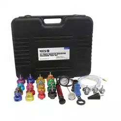
VACUUM & PRESSURE TEST/BLEED KIT
MODEL NO:VS403.V3
Thank you for purchasing a Sealey product. Manufactured to a high standard, this product will, if used according to these instructions,
and properly maintained, give you years of trouble free performance.
IMPORTANT: PLEASE READ THESE INSTRUCTIONS CAREFULLY. NOTE THE SAFE OPERATIONAL REQUIREMENTS, WARNINGS & CAUTIONS. USE
THE PRODUCT CORRECTLY AND WITH CARE FOR THE PURPOSE FOR WHICH IT IS INTENDED. FAILURE TO DO SO MAY CAUSE DAMAGE AND/OR
PERSONAL INJURY AND WILL INVALIDATE THE WARRANTY. KEEP THESE INSTRUCTIONS SAFE FOR FUTURE USE.
Refer to
instruction
manual
Original Language Version
© Jack Sealey Limited
Wear protective
gloves
1. SAFETY
IMPORTANT These instructions are provided as a guide only. Always refer to the manufacturer’s service instructions.
9 Keep this product in good working order and condition, take immediate action to repair or replace damaged parts.
9 Use approved parts only. Unapproved parts will invalidate the warranty.
9 Keep children and unauthorised persons away from the work area.
9 Keep work area clean and tidy and free from unrelated materials.
9 Ensure the work area has adequate lighting.
8 DO NOT use the kit to perform a task for which it is not designed.
8 DO NOT hold pump inlet against the skin whilst using the pump.
8 DO NOT allow untrained persons to use the kit.
8 DO NOT use whilst under the inuence of drugs, alcohol or intoxicating medication.
9 After use, clean equipment and store in a cool, dry, childproof area.
WARNING! Brake uid will damage paintwork. Any spillage should be ushed with water immediately.
WARNING! Brake uid is ammable - keep away from sources of ignition,including hot surfaces e.g. exhaust manifold.
9 Dispose of waste liquids in accordance with local authority regulations.
WARNING! DO NOT pollute the environment by allowing uncontrolled discharge of fluids.
9 Always read and comply with the warnings on the brake uid container.
9 W e a r e y e p r o t e c t i o n a n d k e e p s k i n c o n t a c t t o a m i n i m u m . I f b r a k e u i d e n t e r s e y e s r i n s e w i t h p l e n t y o f w a t e r a n d s e e k m e d i c a l
advice. If swallowed seek medical advice immediately.
2. INTRODUCTION
Professional vacuum/pressure diagnostic tool helps identify a variety of faults on vehicle systems including fuel, ignition, transmission,
emission and air conditioning/heating. Kit also includes reservoirs, hoses and adaptors for bleeding brake and clutch systems.
Features lightweight aluminium body with simple twist function for choice of pressure or vacuum testing. Large rubber easy-to-read
gauge. Supplied in carry-case.
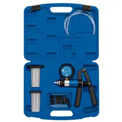
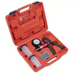
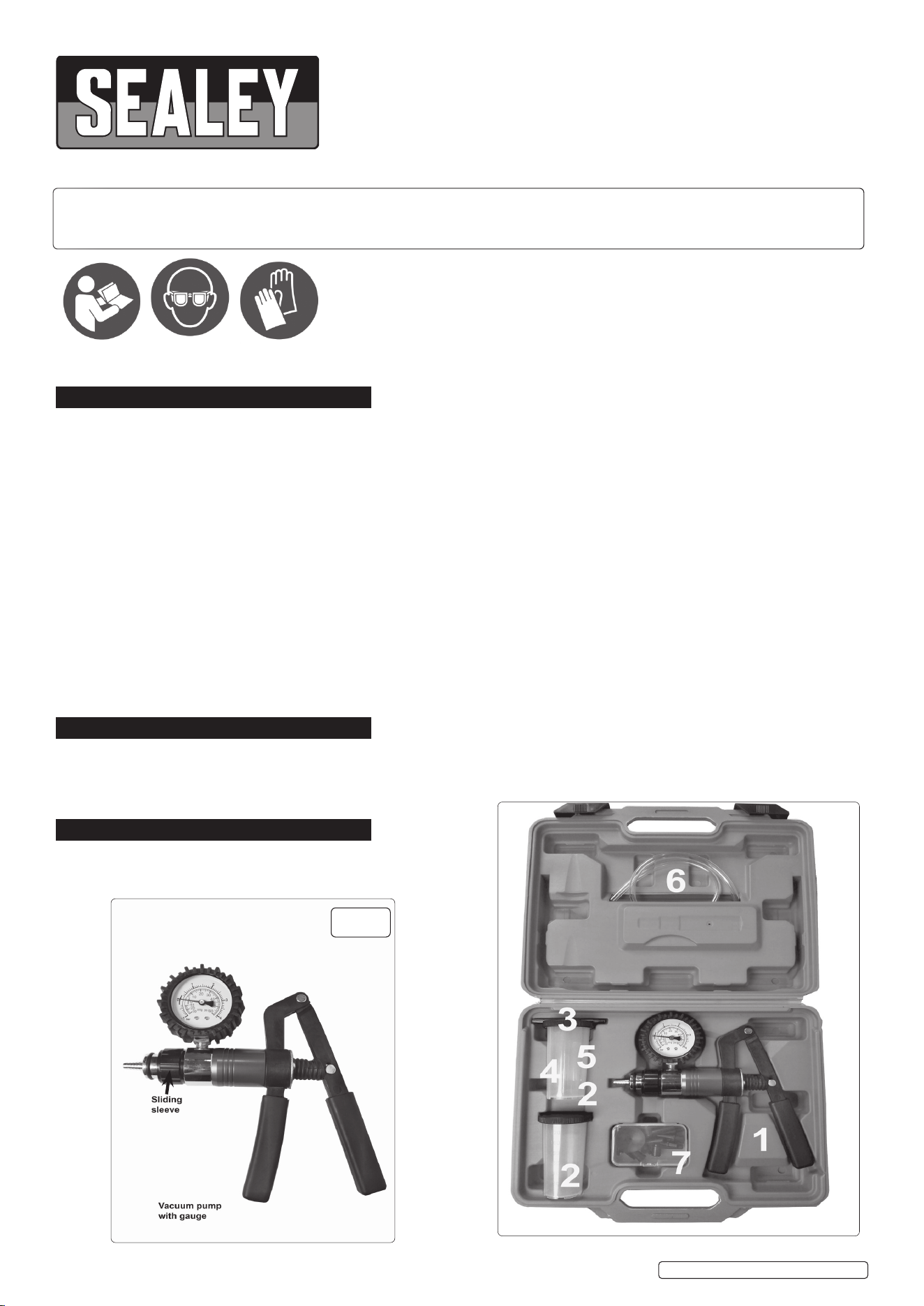
3. CONTENTS
(1).Vacuum Pump, (2) . Fluid Container (x2), (3). Transfer Cap, (4).
Vacuum Hoses; (5). 6mm (x1), (6). 8mm (x2), 6mm (x2), (7) Assorted
Connectors & Blanking Caps (x19)
Wear eye
protection
VS403.V3 Issue: 4 (H,F) 17/05/23
fig.
1
4. APPLICATIONS
The use of a vacuum/pressure gauge is often overlooked when determining mechanical condition and carrying out fault diagnosis on
internal combustion engines. Monitoring actual manifold vacuum is invaluable when troubleshooting engine faults. This can only be
carried out by using a good quality vacuum gauge and this, coupled with a hand-operated vacuum pump, also allows static testing of all
types of vacuum operated systems.
Set out on the following pages are applications that the VS403.V3 vacuum and pressure tester kit can be used for, but it must always
be remembered that these are examples only and reference to manufacturer’s service manuals should always be made for correct testing
procedures and specifications. In addition to this, it is always recommended that additional tests, i.e. compression tests, cylinder leakage
tests, ignition timing checks etc. be carried out to confirm indications of vacuum/pressure gauge readings.
5. OPERATION
5.1. This hand pump and its adaptors can be used to test vacuum motors and control valves as well vacuum or pressure operated systems
and components that require to be properly sealed. The pump and its associated accessories can also be used to bleed brakes. In
pressure testing mode the pump may be utilised to dispense or transfer liquids and provide slight pressure during gravity or pressure
bleeding.
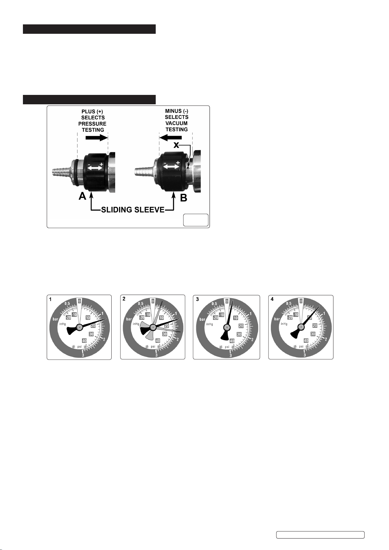
The VS403.V3 can be used for both pressure and vacuum testing by means of the sliding sleeve selector at the front end of the pump.
To select PRESSURE TESTING mode, move the sliding sleeve away from the nozzle end of the pump until it makes contact with the
main body. See fig.2(A) above. The hole indicated at ‘X’ must be fully covered.
To select VACUUM TESTING mode, move the sliding sleeve away from the main body of the pump until it makes contact with the ‘O’
ring just behind the nozzle. See fig.2(B) above. The hole indicated at ‘X’ must be fully revealed.
© Jack Sealey Limited
Original Language Version
VS403.V3 Issue: 4 (H,F) 17/05/23
fig.
2
(1) READING: 16 - 21inHG
DIAGNOSIS: NORMAL
(2) READING: When the
throttle is suddenly opened
then released, the needle
should drop to below 5
inHg then bounce up to
approximately 25 inHg
before settling back to the
original reading.
DIAGNOSIS: NORMAL
(3) READING: Extremely
low but steady
DIAGNOSIS: Leaking
intake manifold system,
Faulty manifold gasket or
carburettor base gasket,
split vacuum hose, seized
open EGR valve.
(4) READING: Reading
low but steady
DIAGNOSIS: Retarded
ignition timing. Confirm
using timing light and
reset to manufacturer’s
specification.
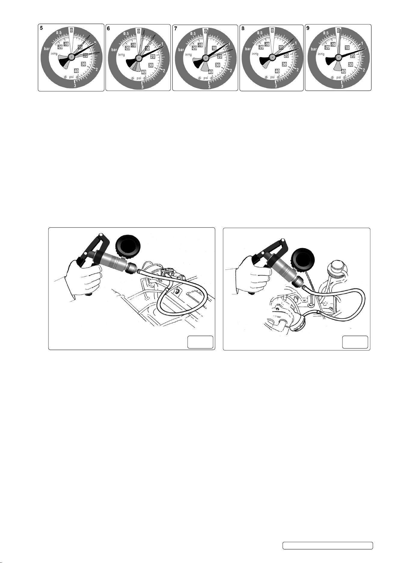
5.2. ANALYSING ENGINE MECHANICAL CONDITION VIA MANIFOLD VACUUM READINGS
The gauge readings shown on the right hand side of this page are only examples of what may be observed. It is important to remember
that it is the action of the needle rather than the actual reading that is more important. Varying engine types will run different manifold
vacuum pressures, depending on camshaft profile, valve overlap, timing etc, so an exact vacuum reading cannot be specified. The
main criteria is that the needle reading is between 16 to 21inHg and steady. Manifold vacuum is also affected by altitude and
it will drop approximately 1inHg for every 1000 feet above sea level so this must also be considered when assessing manifold
vacuum actual readings. Step 1. Run engine until normal operating temperature is reached. Switch engine off. Step 2. Locate and
connect the vacuum gauge to a port directly on the manifold (fig.3) or on the carburettor/throttle body below the throttle
butterfly. Step 3. Start and run the engine at idle, observing the gauge reading. Refer to the gauge examples on the right of this page to
indicate any problems and their possible causes.
5.3. IGNITION SYSTEM VACUUM ADVANCE
On standard points systems and some electronic ignition systems there are two types of advance methods used, both of which must
function correctly to obtain maximum performance and fuel economy. The first method is Mechanical or Centrifugal, which operates
by the use of weights located in the base of the distributor. The weights move outwards advancing ignition timing as engine RPM
increases. This is tested by firstly removing the vacuum advance line to disable the system,then with a timing light connected,
run the engine RPM up checking that the timing advances in accordance with the manufacturer’s specification. The second
method is Vacuum Advance, which senses engine load via manifold vacuum. A vacuum diaphragm is mounted onto the
distributor and connected to a rotating internal base plate which advances or retards timing as required to suit varying engine loads.
To test this system for correct operation, again with the timing light connected, raise the engine RPM and check timing advance
against manufacturer’s specifications. In the event that the vacuum advance is not operating, remove the vacuum line from the
distributor advance mechanism. Connect the VS403.V3 (fig.4) and create a 5-10 inHg vacuum, monitoring the timing at the
same time. If a timing advance is noted this confirms that the vacuum diaphragm and mechanical links are in order and that the fault is
a vacuum supply. To confirm this, connect the VS403.V3 to the vacuum supply line and check the gauge reading. No vacuum
should be noted at idle but when the engine RPM is increased a vacuum increase should be observed. If this does not occur, trace the
vacuum line back checking for restrictions or breaks.
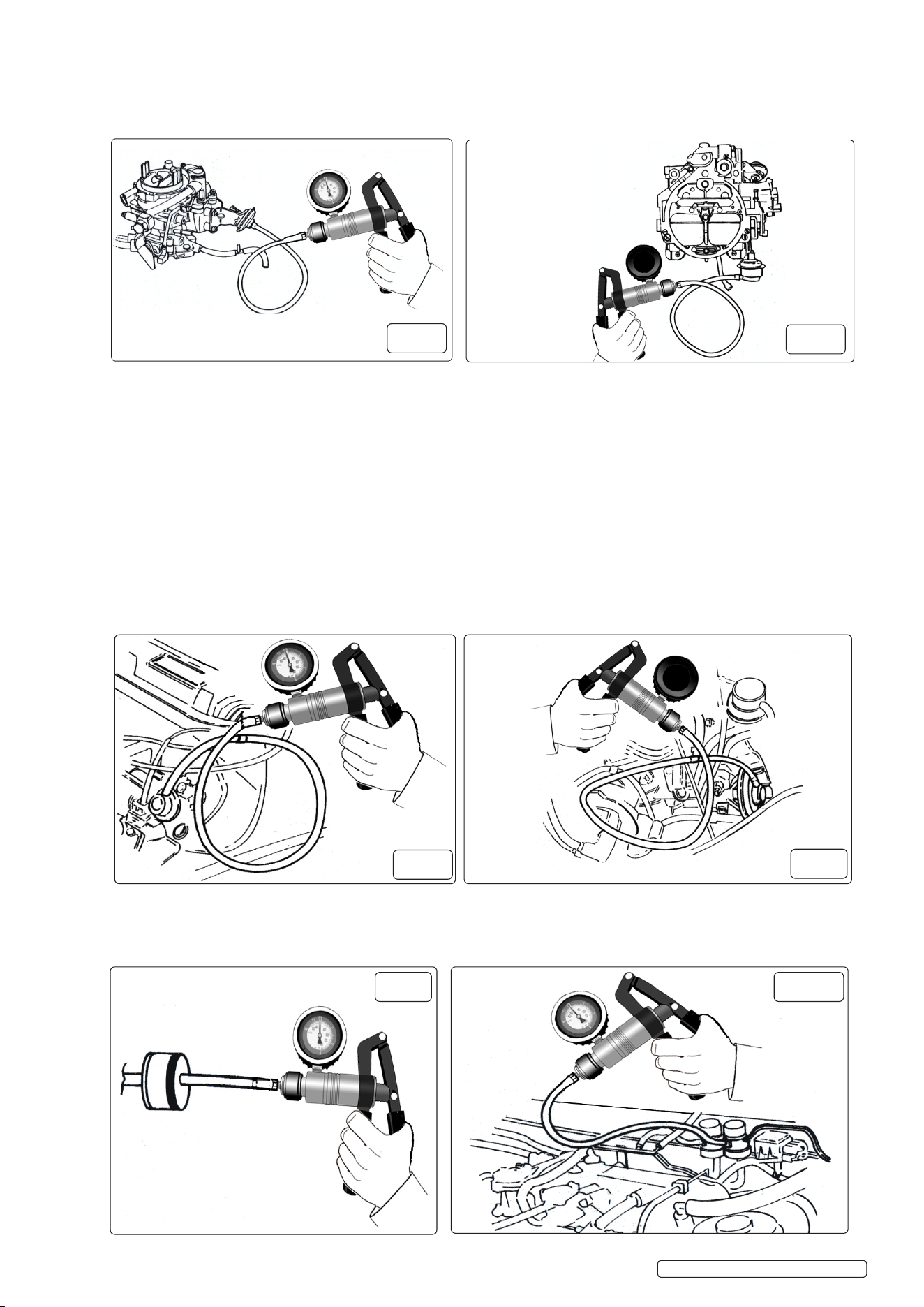
5.4. FUEL SYSTEMS: TESTING MECHANICAL FUEL PUMPS
The VS403.V3 vacuum tester can be used to evaluate the condition of a mechanical fuel pump by testing the vacuum that it is able to
create. Locate and remove the suction line from the pump. Connect the VS403.V3 vacuum tester to the suction port of the pump,
start and run the engine at idle. The vacuum reading that should be observed will vary slightly on different makes and models but as a
general rule approximately 15 inHg of vacuum should be created. This should also be held for approximately 1 minute after engine shut
down. If this vacuum reading is not achieved or the vacuum drops off immediately with the engine shut down, the fuel pump requires
either overhaul or replacement.
5.5. CARBURETTORS
There are many different types of vacuum control systems used on carburettors. Using the VS403.V3 vacuum tester kit allows quick
and accurate testing of these systems. Below are just two examples of tests that can be carried out.
(5) READING: Reading
slightly low and fluctuating
slowly.
DIAGNOSIS: Over lean
or rich mixture. Check and
reset in accordance with
manufacturer’s
specification.
(6) READING: Regular
fluctuation between normal
and low.
DIAGNOSIS: Blown
head gasket between two
adjacent cylinders. Carry
out cylinder leakage test.
(7) READING: Reading
slightly lower than normal
including when throttle
is suddenly opened then
released.
diagnosis: Worn
piston rings. Carry out
compression test.
(8) READING: Regular
drop between normal and
low reading.
DIAGNOSIS: Burnt valve.
(9) READING: Normal
when first started but drops
rapidly when RPM held at
3000.
DIAGNOSIS: Restriction
in exhaust system.
fig.
4
fig.
3
VS403.V3 Issue: 4 (H,F) 17/05/23
Original Language Version
© Jack Sealey Limited
VS403.V3 Issue: 4 (H,F) 17/05/23
Original Language Version
© Jack Sealey Limited
EXAMPLE 1.
Testing a Choke Break Diaphragm. With the engine at normal operating temperature but not running, disconnect the vacuum line to
the diaphragm module. Connect the VS403.V3 vacuum tester (fig.5) and apply approximately15 inHg of vacuum and wait for
30 seconds. No drop in gauge reading should be observed. With the vacuum still applied ensure that the choke butterfly is pulled to the
fully open position.
EXAMPLE 2.
Testing Vacuum Operated Carburettor Secondary Barrel. With the engine at normal operating temperature but not running, remove the
vacuum line from the secondary diaphragm module. Connect the VS403.V3 vacuum tester (fig.6), hold the throttle and secondary air
valve flaps open. Operate the hand pump whilst observing free and easy opening of the secondary throttle butterfly.
TESTING FUEL INJECTION PRESSURE REGULATOR
Multi-point fuel injection rail pressure must vary to suit changing engine loads and fuel delivery requirements. This is done using a
vacuum operated regulator which is connected to the engine manifold vacuum to sense the varying loads. To test the fuel rail pressure,
a gauge is attached to the rail, then engine loads must be created to vary engine manifold vacuum. Simply remove and block off the
vacuum supply line to the pressure regulator, connect and operate the VS403.V3 vacuum pump (fig.7) to simulate vacuum pressures in
accordance with the manufacturer’s specifications and note variation in fuel pressure reading.
TESTING EMISSION CONTROL EXHAUST GAS RECIRCULATION VALVES (EGR)
Start engine and run at idle until normal operating temperature is reached. Remove the vacuum line from the EGR valve and attach
the VS403.V3 vacuum tester kit (fig.8). Operate the hand pump to apply approximately 15 inHg of vacuum. If the EGR Valve is working
correctly the engine idle will become rough. If the idle remains unchanged the valve is possibly seized in the closed position. If the
vacuum is not held,the diaphragm in the valve has failed.
5.6. TESTING ONE-WAY VALVES
Many vacuum operated circuits use in-line one-way valves to apply vacuum in one direction only. To test the function of the valve
remove it from the circuit. Attach the VS403.V3 vacuum tester (fig.9) and operate pump to apply vacuum. In one direction the valve
should hold vacuum and in the opposite direction it should not.
fig.
5
fig.
6
fig.
7
fig.
8
fig.
9
fig.
10
5.7. TESTING ELECTRICALLY OPERATED VACUUM SOLENOIDS
Electrically operated vacuum solenoids are commonly used in control circuits for air conditioning / ventilation systems, emission
control systems, idle step-up systems etc. and testing the function of these when using the VS403.V3 is extremely simple. Locate the
solenoid to be tested and remove the line that goes to the component being tested. Connect the VS403.V3 to the solenoid port (fig.10)
and start the engine. With the system turned off there should be a zero gauge reading. Now turn the system to the ‘on’ position and
a gauge reading equal to the manifold vacuum should be observed. If no reading exists remove the vacuum supply line and test for
manifold vacuum at this point. If the vacuum does exist this indicates that the solenoid is faulty or it is not receiving a ‘switch on’ voltage
(use a multimeter to test this). If no vacuum exists trace the supply line back to the vacuum source checking for kinks or breaks.
5.8. TESTING THERMAL VACUUM SWITCHES
There are many vacuum controlled circuits that must only operate when the engine reaches normal operating temperature. This is
done using thermal switches that remain in an ‘off’ position until a given temperature is reached. To test this type of switch, remove
the vacuum supply line coming from the manifold to the switch and test for manifold vacuum. If this vacuum is correct refit the
supply line to the thermal switch and remove the opposing line from the switch. Attach the VS403.V3 vacuum tester to the port
(fig.11) and start the engine. With a cold engine no reading should be noted. When the engine reaches normal operating temperature
a manifold vacuum reading should be seen.
5.9. TESTING VACUUM OPERATED HEATER TAPS
Climate control ventilation systems are becoming very common on newer vehicles and most of the systems use vacuum operated
taps to control the heating modes. On the majority of makes and models, the system uses vacuum to turn the heater tap
‘on’. To test these remove the supply line from the tap vacuum module and connect the VS403.V3 vacuum tester (fig.12). With the
engine at normal operating temperature locate and feel the heater return hose. With the heater tap in the ‘off’ position, this hose
should be cold. Now operate the vacuum pump to open the tap. The gauge reading must hold. If the tap is in working order, the
return hose will begin to heat. If the hose does not begin to heat this indicates that the tap is faulty.
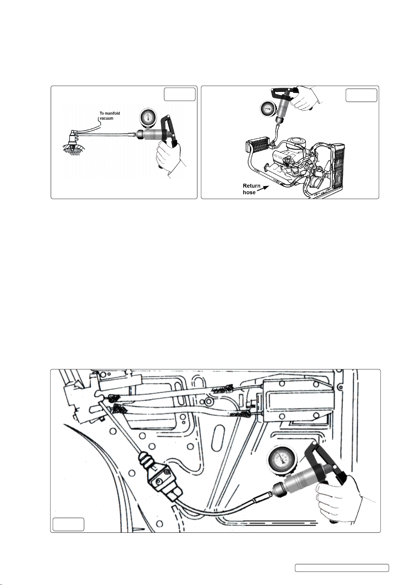
5.10. TESTING VACUUM OPERATED REMOTE CENTRAL LOCKING SYSTEMS
Some makes and models use vacuum operated bellows mounted in each door, to centrally lock and unlock the vehicles doors.
These systems use either manifold vacuum stored in a reservoir for use when the engine is not running or an electrically driven
vacuum pump which operates when the doors are locked or unlocked. In either system, the VS403.V3 vacuum tester is ideal for
testing each individual door bellows. To do this,remove the door trims as required. Remove the vacuum supply lines from the bellows
and attach the VS403.V3 vacuum tester (fig.13) and operate to apply vacuum to the bellows. Wait for 30 seconds, no drop on
the gauge should be noted. If the bellows are found to be in order attach the vacuum supply line to the VS403.V3 vacuum
tester and operate system to test for vacuum supply. If the vacuum supply does not exist or is low trace back down the lines to the
vacuum supply looking for kinks, restrictions or cracked lines. Repair as required and retest.
fig.
11
fig.
12
© Jack Sealey Limited
Original Language Version
VS403.V3 Issue: 4 (H,F) 17/05/23
fig.
13
5.11. TESTING AUTOMATIC TRANSMISSION VACUUM OPERATED MODULATOR VALVES
Automatic transmissions are normally equipped with a vacuum operated modulator valve in order for the automatic transmission to
detect engine loads and adjust shift points to suit. The VS403.V3 vacuum tester can be used to test both that the modulation valve
diaphragm is serviceable and also to simulate varying engine loads so modulator pressure readings can be recorded. To test the
modulator valve diaphragm remove the vacuum supply line from the valve and attach the VS403.V3 vacuum tester. Operate the vacuum
pump until approximately 15 inHg is achieved and monitor the gauge reading for approximately 30 seconds. No vacuum drop should
be noted. To check modulator pressure readings attach a pressure gauge to the appropriate port on the transmission. Remove the
vacuum supply line from the modulator and attach the VS403.V3 vacuum tester (fig.14).Start and run the engine and apply
vacuum pressures. Monitor readings and confirm that these are in conformance with manufacturer specifications.
5.12. BRAKING SYSTEMS
TESTING BRAKE SERVO DIAPHRAGM
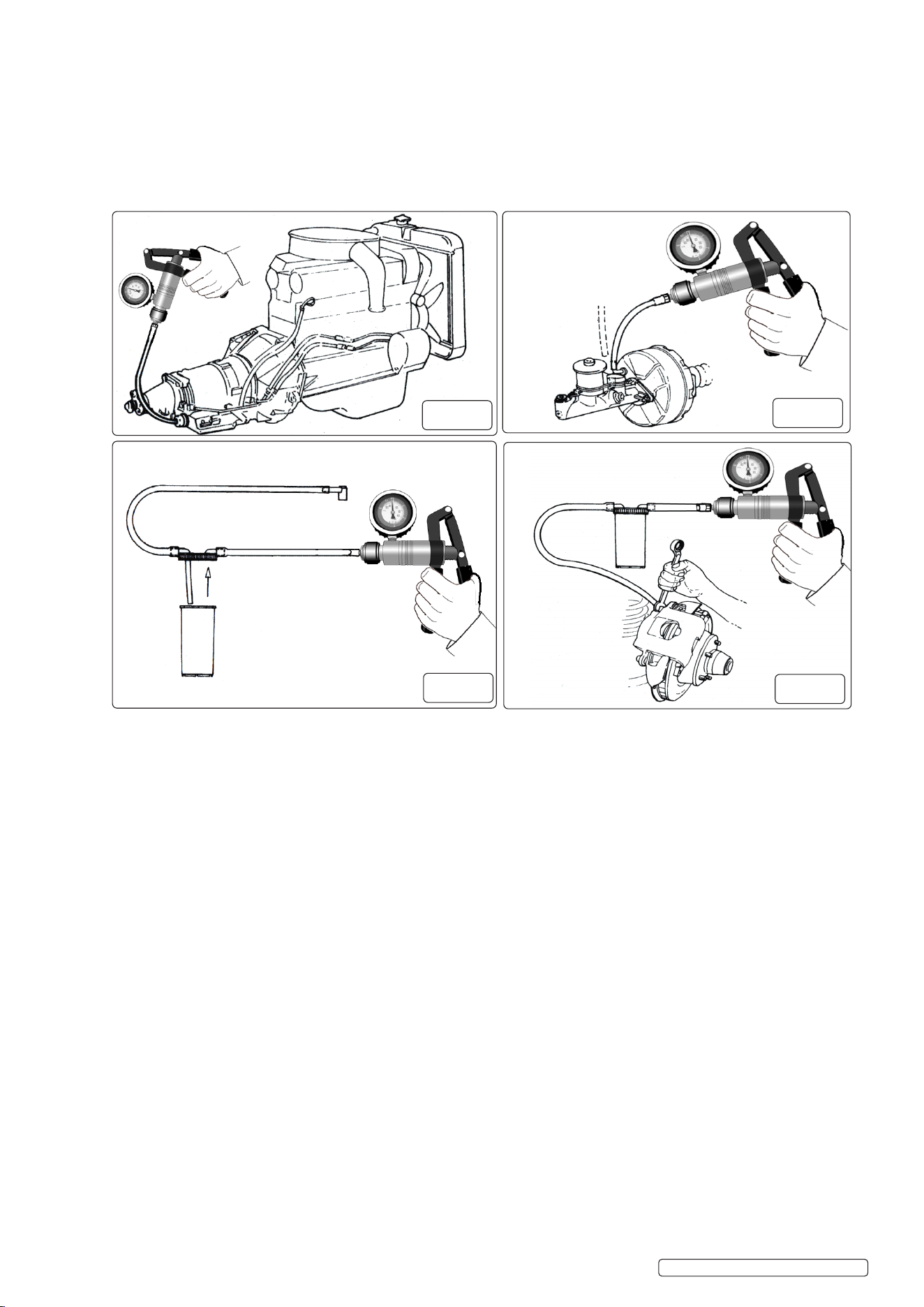
5.12.1. Remove vacuum supply line from brake servo fitting. Attach VS403.V3 vacuum tester to vacuum supply port on servo (fig.15).
Operate pump to create approximately 15 inHg of vacuum and wait for 30 seconds. No vacuum drop should be observed on the
gauge reading. If the vacuum drops this indicates that the brake servo diaphragm is faulty. In this case the servo should be removed
for overhaul by an authorised repairer or replaced.
5.12.2. Brake Bleeding - Assembly of Brake Bleeder Kit
Ensure that the vacuum pump is connected to the brake bleeder reservoir in accordance with the assembly diagram (fig.16). Failure to
do so will result in brake fluid being drawn into the vacuum pump.
5.12.3. BRAKE BLEEDING PROCEDURE.
WARNING! Familiarise yourself with the hazards of brake uid, read manufacturer’s instructions on the container.
8 Do not touch the vehicle’s brake pedal whilst bleeding the brakes.
Refer to the specific vehicle manufacturer’s instructions for brake bleeding and wheel sequence procedure before proceeding. If no
specific instructions from the vehicle manufacturer exist, follow the instructions detailed below.
5.12.3.1. Remove the cap of the vehicle’s master brake fluid reservoir. If the fluid level is not at maximum, top it up.
5.12.3.2. Apply copper grease to the brake bleeding nipples before and after the brake bleeding procedure to reduce the possibility of seized
or broken nipples when the brakes are next bled.
5.12.3.3. Attach the appropriate size bleeding attachment to the bleed nipple on the brake calliper of the first wheel, normally nearest to
master brake fluid reservoir.
5.12.3.4. Operate vacuum pump until approximately 21 inHg vacuum is created.
5.12.3.5. Open the bleed nipple about a quarter of a turn (fig.17). Allow brake fluid to be drawn until no air bubbles are visible in the brake fluid in
the clear hose.
5.12.3.6. Tighten the bleed nipple.
5.12.3.7. Remove the attachment from the brake nipple.
5.12.3.8. Repeat the process as necessary at each wheel.
5.12.3.9. Check the master brake fluid reservoir regularly to ensure that the level does not drop too far, and top up as necessary.
5.12.3.10. Empty bleeder container regularly and do not allow container to overfill as brake fluid will be drawn into vacuum pump.
When brake bleeding and/or fluid changing is complete, test the action of the brake pedal to ensure that the brakes are
working before attempting to drive the vehicle on the road and test the vehicle for satisfactory performance of the braking
system.
5.12.4. Clean bleeder components ‘with water only’ after use.
© Jack Sealey Limited
Original Language Version
VS403.V3 Issue: 4 (H,F) 17/05/23
fig.
14
fig.
15
fig.
16
fig.
17

Sealey Group, Kempson Way, Suffolk Business Park, Bury St Edmunds, Suffolk. IP32 7AR
01284 757500 sales@sealey.co.uk www.sealey.co.uk
ENVIRONMENT PROTECTION
Recycle unwanted materials instead of disposing of them as waste. All tools, accessories and packaging should be sorted,
taken to a recycling centre and disposed of in a manner which is compatible with the environment. When the product
becomes completely unserviceable and requires disposal, drain any fluids (if applicable) into approved containers and
dispose of the product and fluids according to local regulations.
Original Language Version
© Jack Sealey Limited
REGISTER YOUR
PURCHASE HERE
Note: It is our policy to continually improve products and as such we reserve the right to alter data, specifications and component parts without prior
notice. Please note that other versions of this product are available. If you require documentation for alternative versions, please email or call
our technical team on technical@sealey.co.uk or 01284 757505.
Important: No Liability is accepted for incorrect use of this product.
Warranty: Guarantee is 12 months from purchase date, proof of which is required for any claim.
Parts support is available for this product. Please email sales@sealey.co.uk or telephone 01284 757500
5.13. CLUTCH BLEEDING PROCEDURE
Refer to the relevant vehicle manufacturer’s instructions for clutch bleeding procedure. If no specific instructions from the vehicle
manufacturer exist, follow the same basic procedure as the brake bleeding instructions above.
VS403.V3 Issue: 4 (H,F) 17/05/23