
PRESSURE WASHER 170BAR - LANCE CONTROLLED
PRESSURE WITH TSS & ROTABLAST® NOZZLE
MODEL NO: PW2400
Thank you for purchasing a Sealey product. Manufactured to a high standard, this product will, if used according to these instructions,
and properly maintained, give you years of trouble free performance.
IMPORTANT: PLEASE READ THESE INSTRUCTIONS CAREFULLY. NOTE THE SAFE OPERATIONAL REQUIREMENTS, WARNINGS &
CAUTIONS. USE THE PRODUCT CORRECTLY AND WITH CARE FOR THE PURPOSE FOR WHICH IT IS INTENDED. FAILURE TO DO
SO MAY CAUSE DAMAGE AND/OR PERSONAL INJURY AND WILL INVALIDATE THE WARRANTY. KEEP THESE INSTRUCTIONS SAFE
FOR FUTURE USE.
1. SAFETY
1.1. ELECTRICAL SAFETY
WARNING! It is the user’s responsibility to check the following:
9 Check all electrical equipment and appliances to ensure that they are safe before using. Inspect power supply leads, plugs
and all electrical connections for wear and damage. Sealey recommend that an RCD (Residual Current Device) is used with
all electrical products.
Electrical safety information. It is important that the following information is read and understood:
9 Ensure that the insulation on all cables and on the appliance is safe before connecting it to the power supply.
9 Regularly inspect power supply cables and plugs for wear or damage and check all connections to ensure that they are secure.
Important: Ensure that the voltage rating on the appliance suits the power supply to be used and that the plug is tted with the correct fuse.
8 DO NOT pull or carry the appliance by the power cable.
8 DO NOT pull the plug from the socket by the cable.
8 DO NOT use worn or damaged cables, plugs or connectors. Ensure that any faulty item is repaired or is replaced immediately
by a qualied electrician.
9 If the supply cord is damaged, it must be replaced by the manufacturer, its service agent or similarly qualied persons in order to avoid a hazard.
9 The Electric supply connection shall be made by a qualied electrician and comply with IEC 60364-1. It is recommended that the
electric supply to this machine should include either a residual current device that will interrupt the supply if the leakage current to earth
exceeds 30mA for 30ms or a device that will prove the earth circuit.
WARNING! Inadequate extensions cords can be dangerous. If an extension cord is used, it shall be suitable for outdoor use, and the
connection has to be kept dry and o the ground. It is recommended that this is accomplished by means of a cord reel which keeps the
socket at least 60mm above the ground.
WARNING! Always switch o the mains disconnecting switch when leaving the machine unattended.
1.2. GENERAL SAFETY
9 Machines shall not be used by children. Children should be supervised to ensure that they DO NOT play with the machine.
9 The appliance shall be disconnected from its power source during cleaning, service and when replacing parts and, if that the removal of
the plug is foreseen, it shall be clearly indicated that the removal of the plug has to be such that an operator can check from any of the
points to which he has access that the plug remains removed.
WARNING! Risk of explosion – DO NOT spray ammable liquids.
WARNING! High pressure cleaners shall not be used by children or untrained personnel.
WARNING! To ensure machine safety, use only original spare parts from the manufacturer or approved by the manufacture.
WARNING! DO NOT use the machine if a supply cord or important parts of the machine are damaged, e.g. Safety devices, high
pressure hoses, trigger gun.
WARNING! In order to avoid a hazard due to inadvertent resetting of the thermal cut-out, this appliance must not be supplied through
an external switching device, such a timer, or connected to a circuit that is regularly switched on and o by the utility.
9 This machine can be used by people with reduced physical, sensory or mental capabilities or lack of experience and knowledge if they
have been given supervision or instruction concerning use of the machine in a safe way and understand the hazards involved.
WARNING! This machine has been designed for use with cleaning agent supplied or recommended by the manufacturer. The use of
other cleaning agents or chemicals may adversely aect the safety of the machine.
WARNING! High pressure jets can be dangerous if subject to misuse. The jet must not be directed at persons, live electrical
equipment, or the machine itself.
WARNING! DO NOT use this machine within range of persons unless they wear protective clothing.
WARNING! DO NOT direct the jet against yourself or others in order to clean clothes or footwear.
WARNING! High pressure hoses, ttings, and couplings are important for the safety of the machine. Use only hoses, ttings, and
couplings recommended by the manufacturer.
8 NEVER point the high-pressure nozzle at people or animals.
8 NEVER drink alcohol or use drugs while operating the pressure cleaner.
8 NEVER operate the pressure cleaner while standing in water.
8 NEVER touch the electrical plug with wet hands.
8 NEVER let electrical connections rest in water.
8 NEVER operate pressure cleaner without the water turned on.
8 NEVER use hot water with this pressure cleaner.
Refer to
instructions
Wear eye
protection
PW2400 Issue 5 16/04/24
Original Language Version
© Jack Sealey Limited
Wear ear
protection
Wear safety
footwear
Wear protective
clothing
DO NOT direct jet against
yourself, other persons, animals,
electrical equipment or the
machine itself.
2. INTRODUCTION
Features lance controlled pressure adjustment with three power settings. Low power for soft cleaning, Medium power for vehicles and
High power for patio and brickwork. Quick release nozzle system allows for fast selection between fan and Rotablast® nozzle. Pressure
gun includes lock to avoid accidental activation. 2400W Motor produces up to 170bar of pressure with an impressive 450L/hr flow rate.
Automatic Total Stop System (TSS) which switches the motor on and off when the trigger is operated, prolonging motor life. 5m Inline
pressurised hose reel and heavy-duty wheels for ease of use. Built-in detergent tank that filters into the jet stream, perfect for use with the
Low power mode with no need to change the lance. Supplied with 5m power cable for extended reach and snow foam/detergent sprayer.
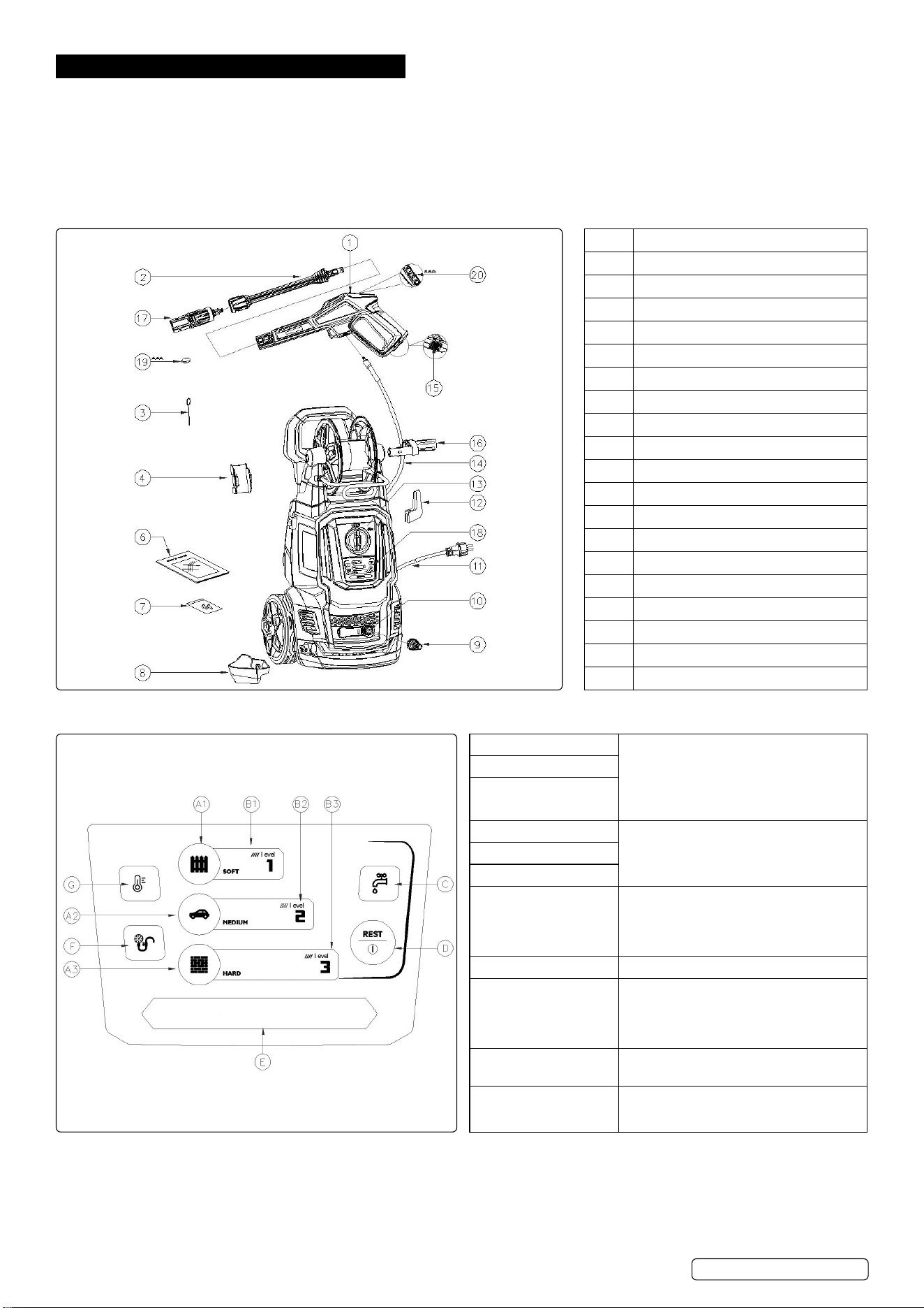
2.1. OVERVIEW
1 Trigger gun
2 Lance
3 Cleaning Pin
4 Gun Holder
5 Water Outlet Pipe
6 Manual
7 Screws Package
8 Gun Saddle
9 Water Inlet Connector
10 Water Inlet Pipe
11 Power Cord
12 Power Cable Hook
13 ON/OFF Switch
14 High Pressure Hose
15 Lock-o Switch
16 Hose Reel Handle
17 Quick Nozzle
18 Host Control Panel Switch
19 Battery
20 Trigger Gun Remote Control Switch
2.2. CONTROL PANEL
A1. Level 1 button
1. Set working level button
2. Wireless pairing mode button (hold
Level 1 and Level 3 button).
3. Exit wireless pairing mode button (hold
one button for 2s).
A2. Level 2 button
A3. Level 3 button
B1. Level 1 indicator
Indicator light shows the current levelB2. Level 2 indicator
B3. Level 3 indicator
C. Water shortage
warning indicator
1. Indicator light is red: water supply
insucient. Motor stops running.
2. The indicator light is green: the water
supply is stable.
D. Multi-function button Run/pause/reset
E. Running indicator
1. Light on = machine operating normally
2. Light o = machine stops running.
3. Light ashes = machine is in wireless
pairing mode
F Holding pressure
indicator
Light On = pump in a pressure-holding
state
G. Over temperature
warning indicator
Green = Motor temperature is normal.
Red = Motor too hot, automatic cut-out.
PW2400 Issue 5 16/04/24
Original Language Version
© Jack Sealey Limited
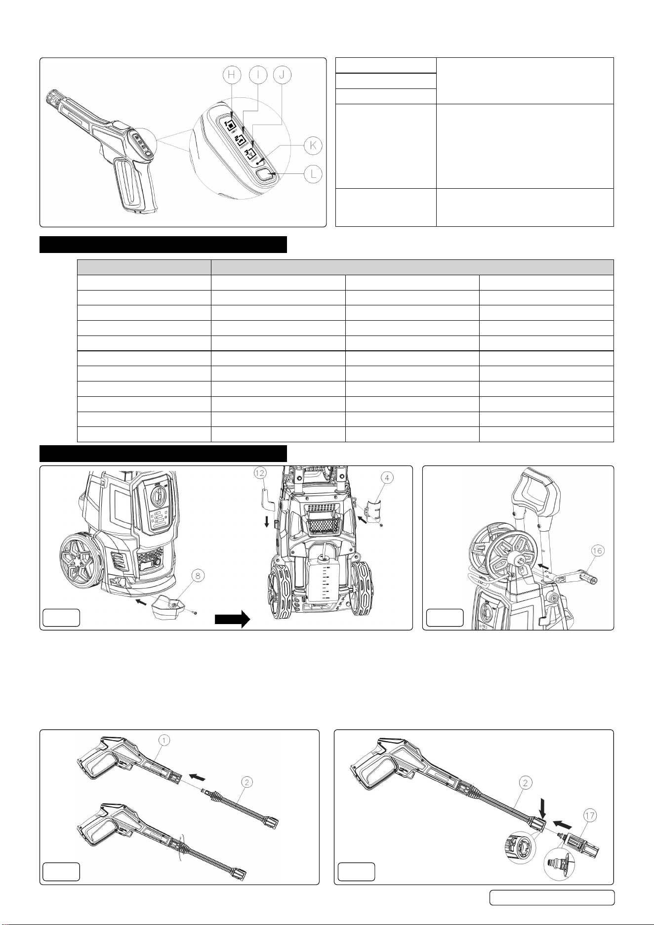
2.3. TRIGGER GUN REMOTE CONTROL SWITCH
H. Level 1 indicator After switching the gear on the remote
control, the indicator shows the currently
set gear, and then the indicator goes out.
I. Level 2 indicator
J. Level 3 indicator
K. Status indicator 1. The status indicator ashes quickly in
pairing mode.
2. The status indicator is o when
successfully paired with the host.
3. The status indicator ashes 3 times
slowly when the battery is low, indicating
that the battery needs to be replaced.
L. Multi-function button 1. Switch working level button
2. Wireless pairing mode button
3. Exit wireless pairing mode button
3. SPECIFICATION
MODEL NO: PW2400
Battery for Trigger Gun: CR2450/3V Noise Pressure: 76.9 dB(A) L
PA
Eective Cleaning Power: 170bar Nozzles: Rotablast® and Fan
Electrical Class: Class 2 Peak Water Temperature: 50°C
Hose Length: 5m Plug Type: 3-Pin BS
IP Rating: IPX5 Power Supply Cable Length: 5m
Maximum Inlet Pressure: 12bar Rated Pressure: 120bar(1740psi)
Maximum Pressure: 170bar(2350psi) Rotablast Nozzle®: Yes
Maximum Water Flow: 450L/hr Supply: 230V~13A
Motor Power: 2400W Vibration/Uncertainty: 1.309 / 1.5m/s
2
Nett Weight: 13.2kg Water Flow Rate: 6.5/7.5L/min
Noise Power: 89.8 dB(A) L
WA
4. ASSEMBLY
FIG.1 FIG.2
4.1. MOUNT THE GUN SADDLE GUN HOLDER AND POWER CABLE HOOK (FIG.1)
4.1.1. Screw the gun saddle (8) tight to the main body (1 screw).
4.1.2. Screw the gun holder (4) tight to the main body (1 screw).
4.1.3. Install power cable hook (12) to the main body.
4.2. MOUNTING OF HOSE REEL HANDLE (FIG.2)
4.2.1. Install hose reel handle (16) to hose reel with a “click”.
NOTE: When attaching, align the projections on the hose reel handle with the grooves on the hose reel.
FIG.3 FIG.4
PW2400 Issue 5 16/04/24
Original Language Version
© Jack Sealey Limited
4.3. ATTACH THE LANCE INTO THE TRIGGER GUN (FIG.3)
4.3.1. Push the lance (2) into the trigger gun (1) and fasten it by turning it through 90°.
4.3.2. When the pieces are joined properly, you cannot separate the two components by pulling straight out on the lance. All attachments
must be inserted into the gun for proper use.
4.4. ATTACH QUICK NOZZLE TO THE LANCE (FIG.4)
4.4.1. When attaching, align the projection on the quick nozzle (17) with the groove on the lance (2) with the button held.
FIG.5A FIG.5B
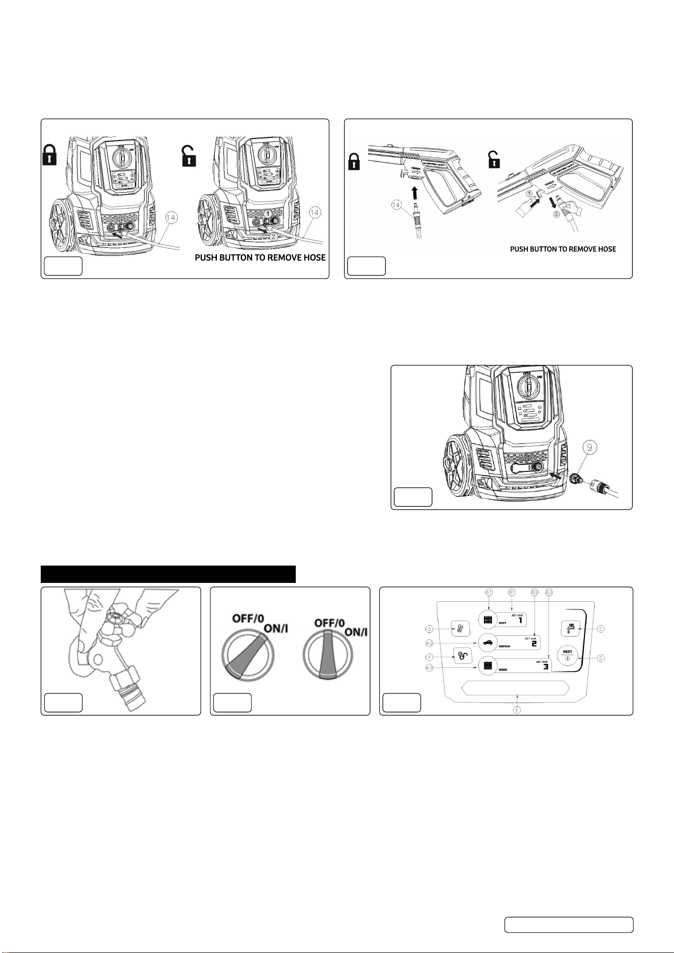
4.5. ATTACH & DETACH THE HIGH PRESSURE HOSE (FIG.5A & 5B)
4.5.1. Attach one end of the high pressure hose to the pressure water outlet pipe of the machine.
4.5.2. Unwind the high pressure hose completely and attach the other end of the high pressure hose to the trigger gun.
NOTE: After the high pressure hose is connected, check the connection by gently pulling on the hose to ensure it stays connected.
Push the lock button and pull to detach the high pressure hose. For detaching the hose easily, please pull the trigger to drain water
from trigger gun when operation is completed and switch is in “ OFF/O ” position.
4.6. ATTACH THE GARDEN HOSE (FIG.6)
4.6.1. Remove the plastic plug from the water inlet pipe of the machine and
screw the water inlet connector onto the water inlet pipe, then connect
one end of the home garden hose (not supplied) to the water inlet
connector and another end to water source.
WARNING! The appliance is INTENDED to be used at a temperature
above 0
o
C.
WARNING! The hose can not be damaged and leak or have an inner
diameter less than 1/2” with a length greater than 8m.
4.7. CONNECT TO THE MAINS POWER SUPPLY
4.7.1. Plug the pressure washer into the mains supply.
4.8. BLEEDING THE GUN
It is very important to bleed the gun before using the pressure cleaner.
Refer to the “Assembly Instructions” to assemble the pressure cleaner. To bleed the gun, simply connect the garden hose to the
pressure cleaner and squeeze the trigger BEFORE turning the electrical supply on. This allows any air trapped inside the pressure
cleaner and gun to be removed before using the unit. Continue holding trigger for approximately one minute to allow any excess air out
of the unit. Water will ow through the gun at low pressure during this procedure.
5. OPERATION
FIG.7 FIG.8 FIG.9
WARNING! During operation the appliance must be positioned on a rm, stable surface. DO NOT loop the hose whilst in use.
5.1. TURN THE WATER SOURCE ON (FIG.7)
5.1.1. Squeeze the trigger for 1 minute to purge the appliance of low pressure water and air.
WARNING! This unit is intended to be used with cold water only! DO NOT use hot water in this pressure washer.
5.2. TURN ON THE SWITCH (FIG.8)
5.2.1. Turn the switch of the high pressure washer to the “ON/I” position, when the switch indicator (B1/B2/C/G) on the host control panel is
green, press the multi-function button (D) to start up the machine. The running indicator light is now on.
WARNING! If the indicator light is not bright or other colours, please contact an authorised service centre.
5.3. SELECT THE RIGHT LEVEL (FIG.9)
5.3.1. Press level 1 button (A1) for cleaning fences, cement terraces, stones, bricks, etc.
5.3.2. Press level 2 button (A2) for cleaning cars, boats, motorcycles, etc.
5.3.3. Press level 3 button for cleaning barbecue grills, power equipment and garden tools, etc.
NOTE: The default level is level 2 after start.
5.4. WIRELESS PAIRING
5.4.1. Machine controls: long press Level 1 button and Level 3 button at the same time for 2 seconds to enter wireless pairing. In pairing
mode, the indicator light ashes slowly, long press one button for 2 seconds to exit pairing.
FIG.6
PW2400 Issue 5 16/04/24
Original Language Version
© Jack Sealey Limited
5.4.2. Remote control: long press multi-function button for 5 seconds to enter pairing mode, the indicator light ashes fast. If the pairing is
successful, the indicator light goes o, and the level indicator light will show the current machine level; if the pairing fails, the machine
will exit pairing mode after 10 seconds. You can also press the multi-function button for 2 seconds to manually exit the pairing mode.
NOTE: After successfully paired:, the machine will only be controlled by the paired remote control.
FIG.10 FIG.11 FIG.12
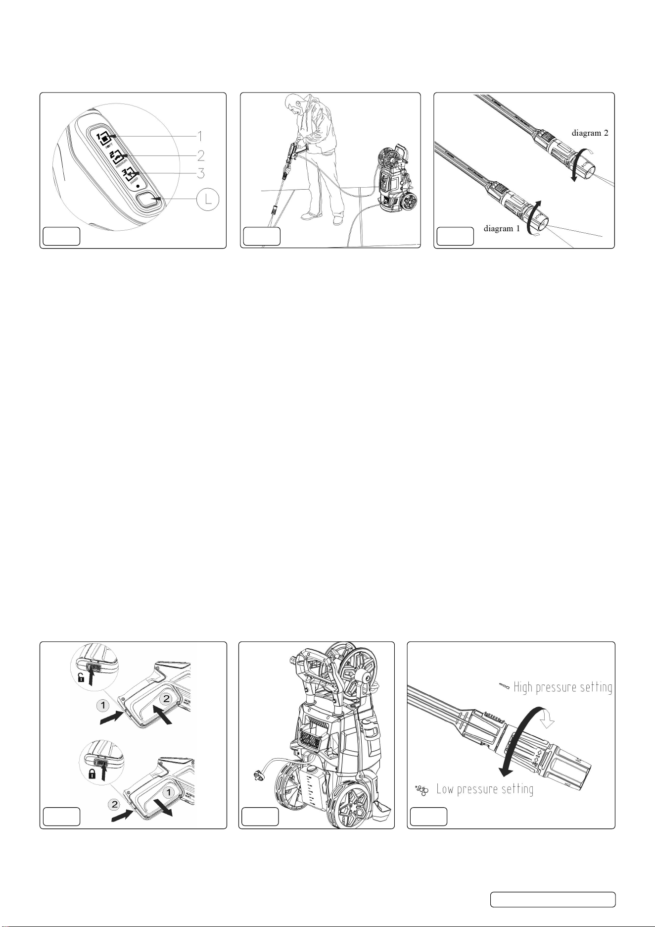
5.5. TRIGGER GUN REMOTE CONTROL BOARD OPERATION (FIG.10)
5.5.1. When the host is successfully paired, lightly press the multi-function button (L) to switch the levels, the level switching sequence is 1-2-
3-1. When the level are switched, the level indicator shows the currently set level, and then the indicator goes out.
NOTE: The default level is level 2 after start.
NOTE: The adjustable control range of the remote control is within 10m. Try to avoid interference signals between the host and the
remote control when pairing.
5.6. CLEANING (FIG.11 & 12)
WARNING! Before pressing trigger,make sure lock-o switch is in “unlock” position.
WARNING! When operating the machine, it is forbidden to use in the inverted state.
NOTE: Whenever you use the high pressure washer, we suggest you grip the in the right position, with one hand on the handle and
the other on the adjustable spray nozzle.
5.6.1. Squeeze the trigger, high pressure water ow will come out.
5.6.2. Rotate the adjustable nozzle collar to change it from a full fan spray to a direct stream spray (g.12).
NOTE: The water shortage warning light (2.2-C) will be red and ashing, and the motor will stop running when there is water shortage
or water ow is unstable. Please check if the water source is connected and turned on.
5.6.3. Begin with the nozzle 1-2ft away from the surface and approach with caution. Spraying too close can damage the surface.
WARNING! DO NOT connect the machine to water supplies that are dirty, rusty, muddy, or corrosive, including window cleaning
liquids, plant foods, or fertilizers etc.
5.6.4. Release the trigger and turn o the multi-function button on the main unit or the trigger gun.
5.6.5. After cleaning work is completed, turn the switch to the “OFF/O” position.
5.6.6. Turn o the water supply.
NOTE: When not in use, make sure Lock-o switch is in “Lock” position.
NOTE: When the pump is still in the pressure-holding state after shutdown, the pressure-holding indicator (2.2-F) will ash slowly until
the power is exhausted. A gun needs to be red to release the water pressure in the water pump.
5.6.7. Unplug the power cord from the power outlet.
WARNING! Check that the supply voltage and frequency correspond to those specied on the appliance data plate. The appliance
should only be connected to a mains power supply via a security breaker (Max.30mA) to cut o the electricity supply in the instance of
a short circuit.
5.7. SAFETY VALVE AND/OR PRESSURE LIMITING VALVE
WARNING! DO NOT tamper with or adjust the safety valve setting.
The safety valve is also a pressure limiting valve. When the gun trigger is released,the valve opens, pressure switch action, the
machine automatically shut down. If the gun nozzle is blocked, will cause the machine pressure rises, the safety valve opens, the
pressure switch action, the machine automatically shut down, you can refer to the following to use a needle to clean the nozzle.
FIG.13 FIG.14 FIG.15
5.8. THE SAFETY BUTTON OF TRIGGER GUN (FIG.13)
5.8.1. Press the unlock button to unlock the trigger for spray operation.
5.8.2. When the trigger is released, it will return to the o position automatically.
5.8.3. When not using the pressure cleaner, press the lock button to keep from accidentally engaging the high pressure spray.
PW2400 Issue 5 16/04/24
Original Language Version
© Jack Sealey Limited
5.9. TO WASH WITH DETERGENT (FIG.14 & 15)
5.9.1. Unscrew the cap on the detergent bottle and add appropriate detergent. Then screw the soap tank knob.
5.9.2. Rotate the High/Low pressure nozzle into low pressure mode.
5.9.3. Squeeze the trigger, detergent will come out through the adjustable nozzle.
5.9.4. Apply detergent so it thoroughly covers cleaning surface.
5.9.5. Allow detergent to remain on the surface for few minutes, this is a good time to use a brush to lightly scrub heavily soiled areas.
5.9.6. Set the adjustable nozzle into high pressure mode.
FIG.16
FIG.17
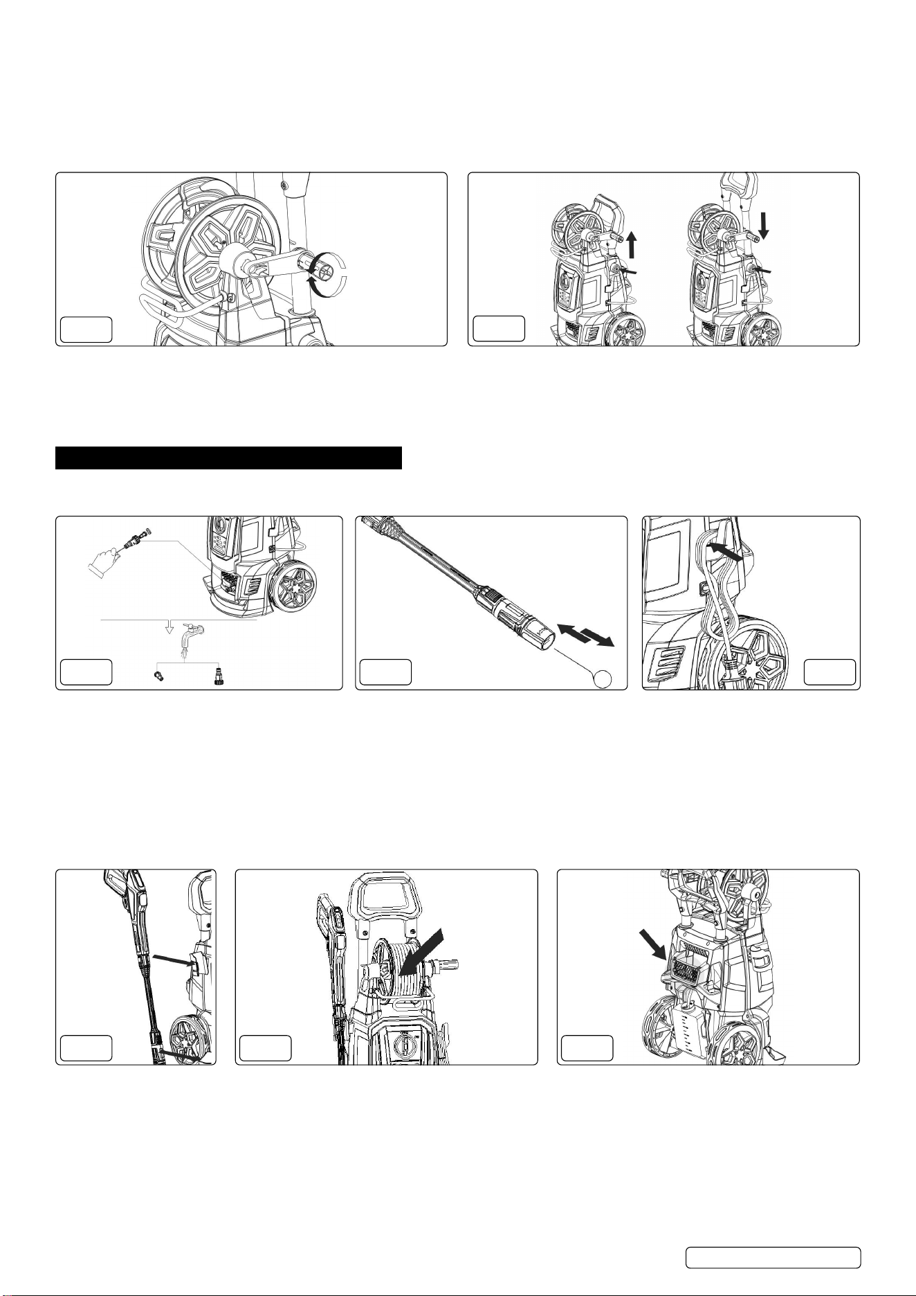
5.10. USE THE HOSE REEL (FIG.16)
5.10.1. To unwind the hose, turn hose reel handle clockwise, to wind the hose,turn hose reel handle counter clockwise.
NOTE: Pull the hose reel handle out and uncoil hose from the hose reel before use.
5.11. TELESCOPIC HANDLE (FIG.17)
5.11.1. To raise/lower the handle, press the button and move the handle upwards/downwards. The handle will ‘click’ into position.
6. MAINTENANCE
NOTE: Any maintenance operations not covered by this chapter should be carried out by an Authorized sales and service centre.
WARNING! Always disconnect the plug from the power socket before carrying out any work on the appliance.
FIG.18 FIG.19 FIG.20
6.1. CLEANING OF WATER INLET FILTER (FIG.18)
The water lter installed inside the water inlet connector should be cleaned periodically. Rinse it with clean tap water, and then place it
back into the water inlet connector .
6.2. CLEANING THE NOZZLE (FIG.19)
Using the nozzle tip cleaner provided ( or an unfold paper clip), insert the wire into the nozzle hole and move back and forth until debris
is dislodged. Flush the nozzle backwards with water.
6.3. CLEANING OF MACHINE VENTS
The machine should be kept clean so as to let cooling air pass freely through the machine vents.
6.4. GREASING OR COUPLINGS
To ensure easy connection, the couplings should be greased regularly.
FIG.21 FIG.22 FIG.23
6.5. STORAGE
6.5.1. The machine should be stored in a frost-free area with a temperature above 0
o
C (32
o
F)
6.5.2. Pump, hose and accessories should always be emptied of water prior to storing as follows:
6.5.2.1. Stop the machine (turn the ON/OFF switch to position “OFF/O”) and detach water hose and accessory.
6.5.2.2. Restart the machine and activate the trigger. Let the machine run until no more water runs through the spray handle.
6.5.2.3. Stop the machine and unplug, coil up the power cord and placed it on the power cable hook (g.20).
6.5.2.4. Place gun and lance on the gun holder (g.21)
6.5.2.5. Coil the high pressure hose on the hose reel (g.22).
6.5.2.6. Place small accessories (e.g.: connector ) in the storage space on the back of the machine (g.23).
PW2400 Issue 5 16/04/24
Original Language Version
© Jack Sealey Limited
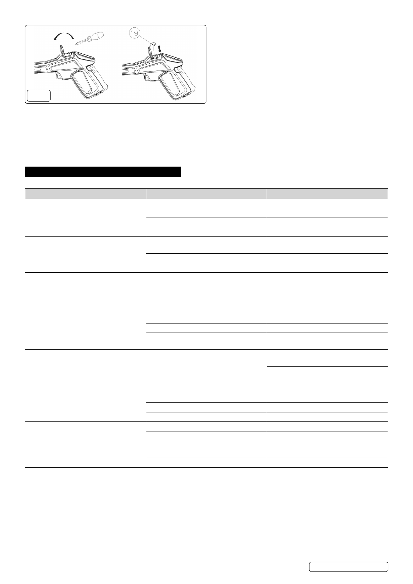
FIG.24
6.6. TRIGGER GUN BATTERY REPLACEMENT (FIG.24)
6.6.1. Open the battery cover of the trigger gun with a tool, put the battery (CR2450/3V) into the battery slot of the gun, and then cover the
battery cover back to its original position.
6.6.2. Press the multi-function button on the remote control of the spray gun and check whether the status indicator ashes quickly. If it does
not ash or ashes slowly 3 times, the battery needs to be replaced.
NOTE: Please make sure that the battery’s positive and negative directions are placed in the correct direction, with the positive side
facing upwards. When using the remote control board to operate the machine, the battery model recommended by the manufacturer
must be used.
7. TROUBLESHOOTING
Please ensure that you check the following before contacting an authorised service centre:
SYMPTOM CAUSE RECOMMENDED ACTION
Machine refuses to start Machine not plugged in Plug in machine.
Defective socket Try another socket.
Fuse has blown Replace fuse, switch o other machines.
Defective extension cable Try without the extension cable.
Fluctuating pressure Pump sucking air Check that hoses and connections are
airtight.
Valves dirty, worn out or stuck Clean and replace or refer to local distributor.
Pump seals worn out Clean and replace or refer to local distributor.
Machine stops suddenly Fuse has blown Replace fuse. Switch o other machines.
Incorrect mains voltage Check that the mains voltage corresponds to
specication on the model tag.
Over temperature warning light is red Leave the washer for 5 minutes to cool down,
press the multi-function button on the panel
switch to restart.
Nozzle partially blocked Clean the nozzle.
Water shortage warning light is red Check if the water source is connected and
turned on, and if the water supply is sucient
Fuse blows Fuse too small Change to an installation higher than the
amp. Consumption of the machine.
You may try without the extension cable.
Machine pulsating Air in inlet hose/pump Allow machine to run with open trigger until
regular working pressure resumes.
Nozzle partially blocked Clean the nozzle.
Water lter blocked Clean the lter.
Hose kinked Straighten out hose.
Machine starts, but no water comes out Pump/hose or accessory frozen Wait for pump/hoses or accessory to thaw.
Water shortage warning light is red Check if the water source is connected and
turned on, and if the water supply is sucient
Water lter blocked Clean the lter.
Nozzle blocked Clean the nozzle.
In case problems other than the above occur, please contact an authorised service centre:
PW2400 Issue 5 16/04/24
Original Language Version
© Jack Sealey Limited
Sealey Group, Kempson Way, Suffolk Business Park, Bury St Edmunds, Suffolk. IP32 7AR
01284 757500 sales@sealey.co.uk www.sealey.co.uk
Note: It is our policy to continually improve products and as such we reserve the right to alter data, specications and component parts without prior notice.
Important: No Liability is accepted for incorrect use of this product.
Warranty: Guarantee is 12 months from purchase date, proof of which is required for any claim.
ENVIRONMENT PROTECTION
Recycle unwanted materials instead of disposing of them as waste. All tools, accessories and packaging should be
sorted, taken to a recycling centre and disposed of in a manner which is compatible with the environment. When
the product becomes completely unserviceable and requires disposal, drain any uids (if applicable) into approved
containers and dispose of the product and uids according to local regulations.
REGISTER YOUR
PURCHASE HERE
WEEE REGULATIONS
Dispose of this product at the end of its working life in compliance with the EU Directive on Waste Electrical and Electronic
Equipment (WEEE). When the product is no longer required, it must be disposed of in an environmentally protective way. Contact
your local solid waste authority for recycling information.
BATTERY REMOVAL
Under the Waste Batteries and Accumulators Regulations 2009, Jack Sealey Ltd are required to inform potential purchasers of products
containing batteries (as defined within these regulations), that they are registered with Valpak’s registered compliance scheme. Jack
Sealey Ltd Batteries Producer Registration Number (BPRN) is BPRN00705.
PW2400 Issue 5 16/04/24
Original Language Version
© Jack Sealey Limited