
Model No.: # 355-0672 / 355-0673 / 355-0674
PAGE: 1 / 12
220104
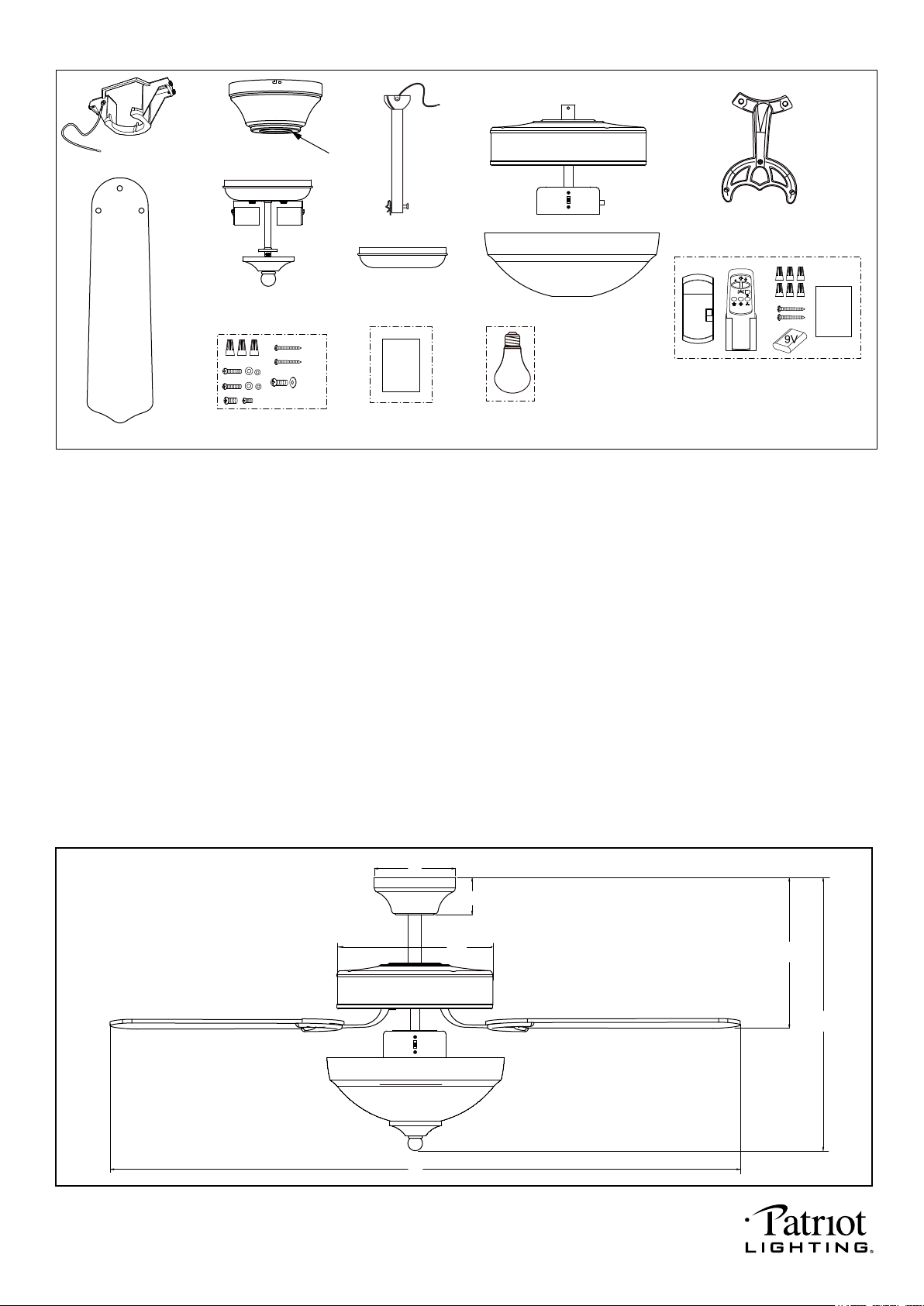
Unpack your fan and check the contents. You should have the following items.
1.) Hanger Bracket
2.) Canopy
3.) Canopy Cover (Remove the Preassembled Canopy Cover from the Canopy Before Installation.)
4.) Downrod Set (Included Hanger Ball, 4” Downrod, Hanger Pin & Lock Pin)
5.) Fan Fixture Set
6.) Blade Bracket (5 PCS)
7.) Fan Blade (5 PCS)
8.) Fan Light
9.) Switch Box Cover
10.) Glass Shade
11.) Remote Control Set (Includes Receiver & Transmitter & Wire Connectors & Battery
& Screws & Remote Control Instructions)
12.) Assembly Kit
13.) Installation Instructions
14.) 9W E26 (M) Base A19 Type LED Bulb (2PCS)
Package Contents:
A. 10" B. 17" C. 2-1/4" D. 11" E. 5-1/8" F. 52"
Dimension Reference (Installed with 4” Downrod)
Installation
Instructions
E
F
A
B
C
D
PAGE: 2 / 12
1
2
7
8
9
10
11
12
14
13
4
3
5 6
X16
Remote
Control
Instructions
220104
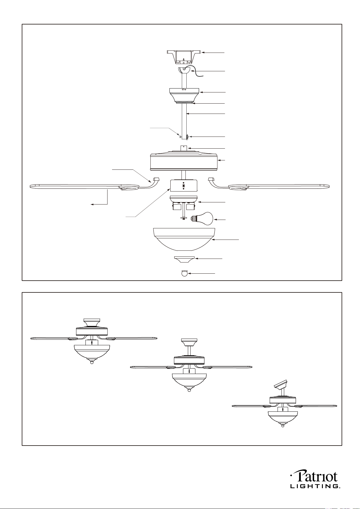
Hanger Bracket
Canopy
Downrod
Hanger Ball
Hanger Pin
Blade Bracket
Collar
Lock Pin
Housing
Fan Light
LED Bulb
Blade
Switch Box
Ceiling Mount
Downrod Mount
Sloped Ceiling Mount (Up to 23 degrees)
Glass Shade
End Cap
Finial
Exploded View Detail
Triple Mount Options
PAGE: 3 / 12
Canopy Cover
220104
PAGE: 4 / 12
Safety Instructions
READ ALL SAFETY INFORMATION AND INSTALLATION INSTRUCTIONS BEFORE YOU BEGIN TO
INSTALL THE FAN AND SAVE INSTRUCTIONS.
All set screws of the fan must be checked and retightened where necessary before installation.
To reduce the risk of personal injury, do not bend the blade brackets when installing the brackets,
balancing the blades or cleaning the fan. Do not insert foreign objects between rotating fan blades.
Before changing the fan direction, turn off the fan and wait for the fan blades to stop completely.
The safeguards provided by these safety instructions and by the separate installation
instructions are not meant to cover all possible conditions and situations that may occur. It must be
understood that common sense, caution and care are factors which can not be built into this product.
These factors must be supplied by the person(s) installing, caring for and operating the fan.
TO AVOID RISK OF ELECTRIC SHOCK, BE SURE TO SHUT OFF POWER AT THE MAIN
FUSE OR CIRCUIT BREAKER BOX BEFORE INSTALLING OR SERVICING THIS
FIXTURE. TURNING OFF THE ELECTRICAL POWER BY USING THE LIGHT SWITCH
IS NOT SUFFICIENT TO PREVENT ELECTRICAL SHOCK.
TO REDUCE THE RISK OF INJURY, INSTALL THE FAN SO THAT THE BLADES ARE
AT LEAST 7 FEET (2.1 METERS) ABOVE THE FLOOR AND AT LEAST 18 INCHES
(0.5 METERS) FROM THE TIP OF THE BLADES TO THE WALL.
TO REDUCE THE RISK OF FIRE, ELECTRIC SHOCK, OR PERSONAL INJURY, MOUNT
TO OUTLET BOX MARKED "ACCEPTABLE FOR FAN SUPPORT" AND USE MOUNTING
SCREWS PROVIDED WITH THE OUTLET BOX.
THE INSTALLATION HAS TO BE IN ACCORDANCE WITH THE NATIONAL ELECTRICAL
CODE, ANSI/NFPA 70-1999 AND LOCAL CODES. IF YOU ARE UNFAMILIAR WITH THE
METHODS OF INSTALLING ELECTRICAL WIRING, SEEK THE SERVICES OF A
QUALIFIED LICENSED ELECTRICIAN.
WARNING
220104
(
For ceiling mount only):
Remove the canopy cover from the
canopy.
Remove three of six screws (every
other one) securing the motor collar
to the top of the fan motor housing.
Attach the canopy to the housing
with three screws.
(
For ceiling mount only):
Raise the fan and place the canopy
on the hanger bracket hook for wiring.
Go to Fig.10 for the next steps.
(
For downrod mount only):
Thread the motor wires through the
canopy and downrod.
PAGE: 5 / 12
Installation Steps :
Fig.3
Fig.4
Canopy
Hanger Pin
Lock Pin
Collar
Housing
INSTALLATION INSTRUCTIONS
IMPORTANT:
BEFORE YOU BEGIN INSTALLATION, CAREFULLY READ ALL INFORMATION PROVIDED IN THE SAFETY
INSTRUCTIONS AND INSTALLATION INSTRUCTIONS. IF IN DOUBT, CONSULT A QUALIFIED
ELECTRICIAN.
SAVE ALL INSTRUCTIONS.
NOTE: The fan weight is 15.21 lbs (6.9 kgs). Be sure the outlet box you are using is securely attached to the
building structure and can support the full weight of the fan. Failing to do so can result in serious injury.
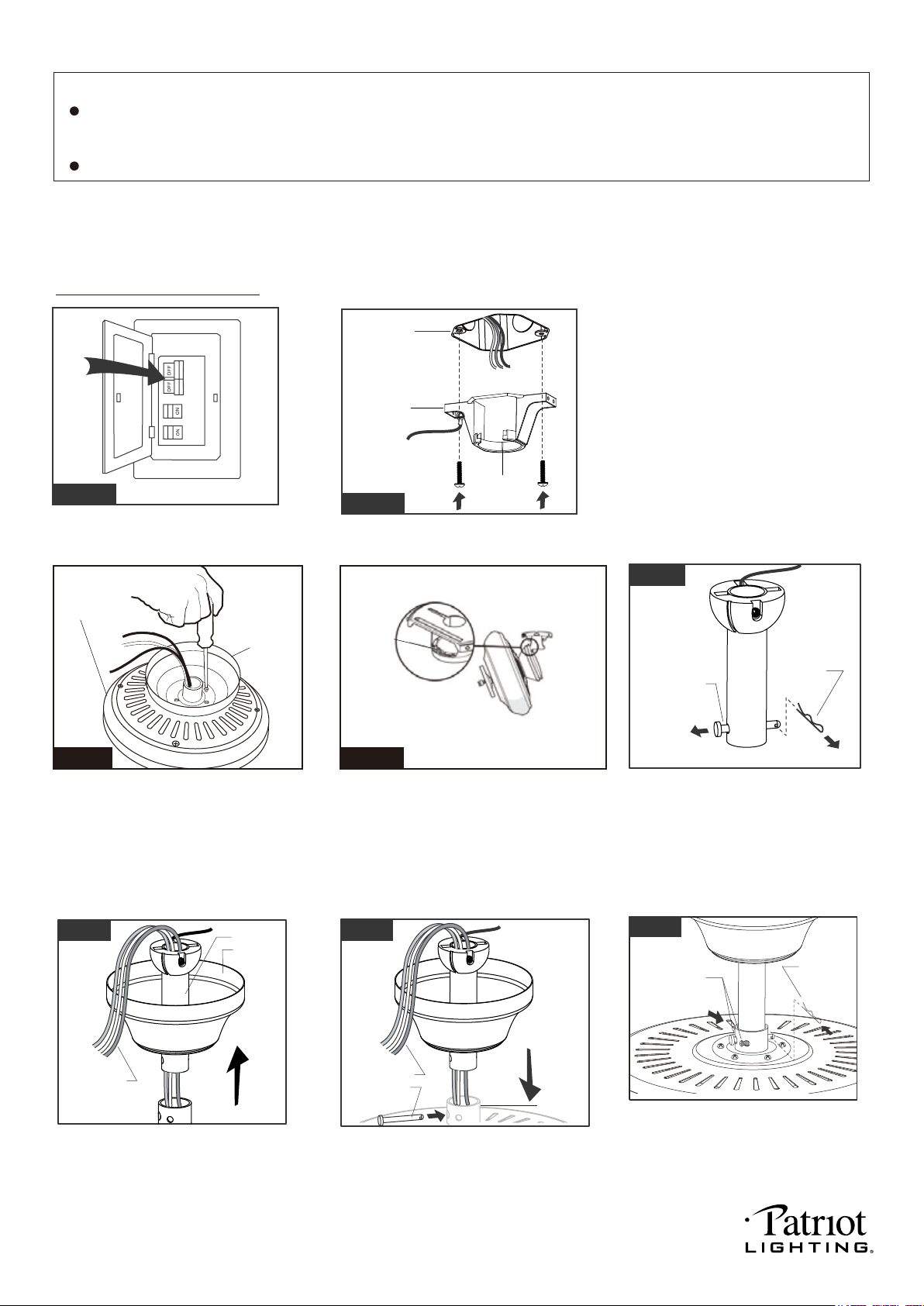
Tighten the hanger bracket to the outlet
box with two mounting screws. (To reduce
the risk of fire, electric shock, or personal
injury, mount to an outlet box marked
"Acceptable for fan support" and use
mounting screws provided with the outlet
box.)
Note: For sloped ceiling installation, make
sure that the chip of the hanger bracket
is toward the floor.
Fig.1
Turn OFF the electric circuit at the
main fuse or circuit breaker box.
(
For downrod mount only):
Remove the lock pin and take off
the hanger pin.
Fig.5
(
For downrod mount only):
Loosen the collar screws out part way.
Insert the downrod into the collar.
Slide hanger pin through holes of
collar and downrod.
Fig.6
Motor Wires
Downrod
Canopy
Fig.7
Motor Wires
Hanger Pin
(
For downrod mount only):
Tighten the two collar screws.
Slide lock pin into hanger
pin until it locks into position.
Fig.8
Lock Pin
Collar Screws
Hanger
Bracket
Chip
Fig.2
Outlet Box
Hanger
Bracket
Hook
220104
PAGE: 6 / 12
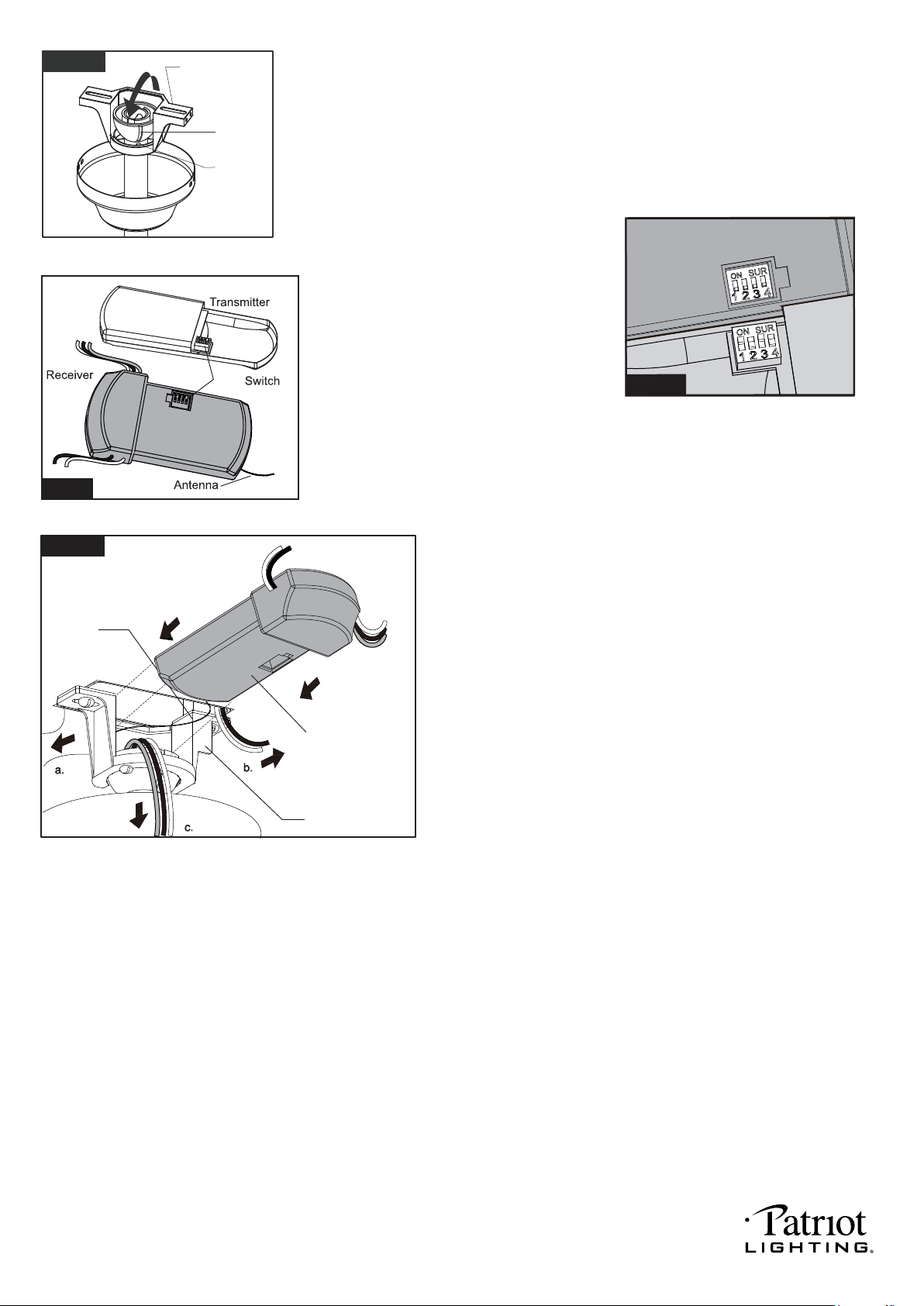
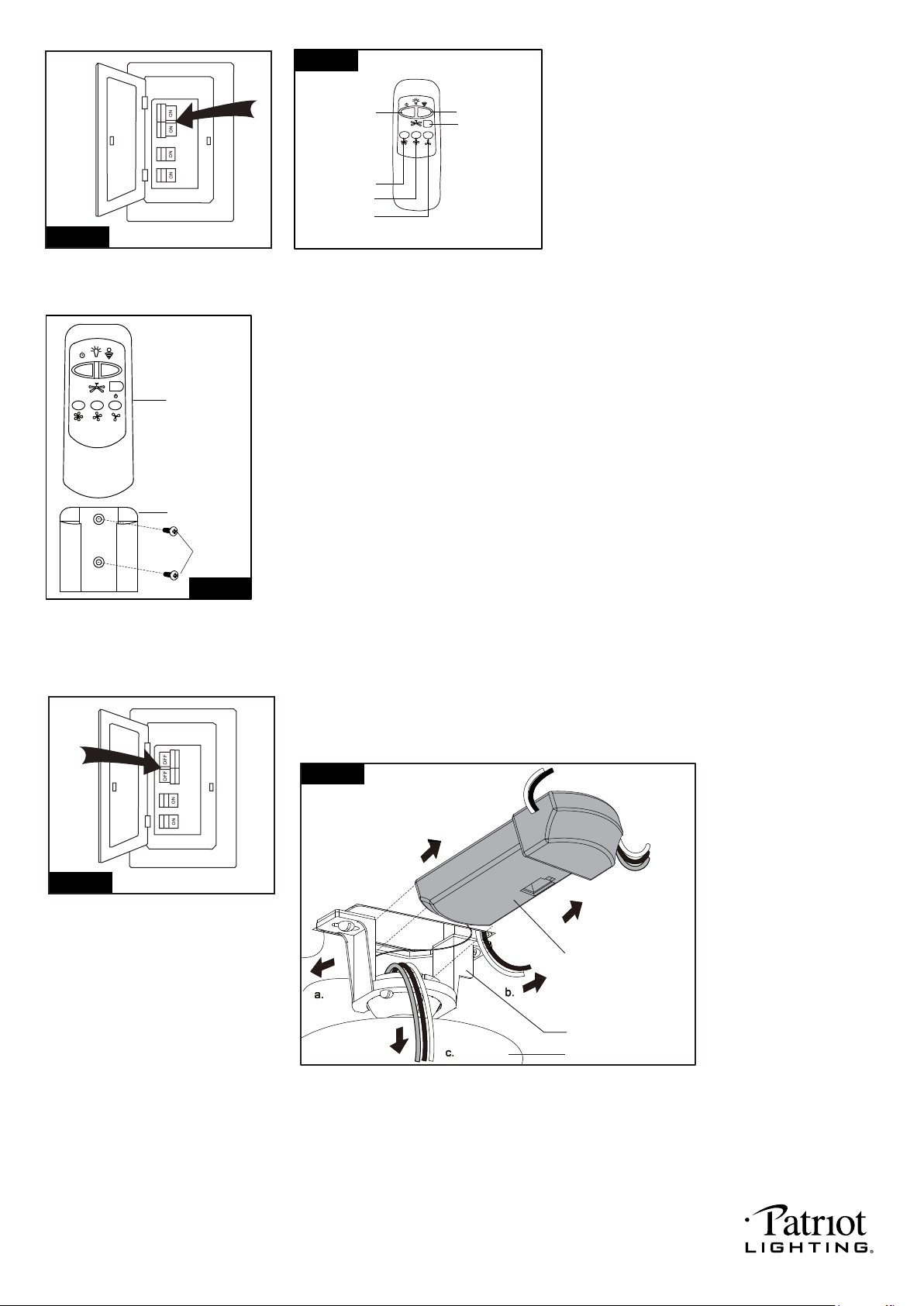
Move ground wires (a), outlet box wires (b), and
motor wires (c) away from the center of the hanger
bracket. Then slide receiver through hanger
bracket as shown. Antenna end first, until it is
centered. Finally, cut motor wires (c) to length
needed for connections.
Fig.10
Code example:
1-ON 2-OFF 3-ON 4-OFF on both SUR
Switches.
Note: If you have two ceiling fans
with 2 remote control units, set 2
different codes for each set of
transmitter / receiver.
(For downrod mount only):
Hang the fan on hanger bracket, and make
sure the slot of hanger ball is snapped into
the chip of hanger bracket exactly.
Note: For sloped ceiling installation, make
sure the slot of hanger ball and the chip of
hanger bracket face down.
Slot
Chip
Hanger Bracket
Fig.9
Both the transmitter and receiver have a 4-key
unit code on each SUR Switch (Fig.10) and by
default, all keys are pre-set to the "off" position.
This means that the transmitter and receiver are
already paired together. However, if you have
multiple fans and remote controls and want to
avoid interference between them, you can "pair"
other transmitters and receivers together by
adjusting the SUR switches, so the same
numbered keys are in the "ON" position
on both (Fig.10a).
Note: The ceiling fan may work abnormally
if there is interference from other remote
controls.
SUR
ON
SUR
ON SUR
Fig.10a
Hanger Bracket
Receiver
Antenna
Fig.11
220104
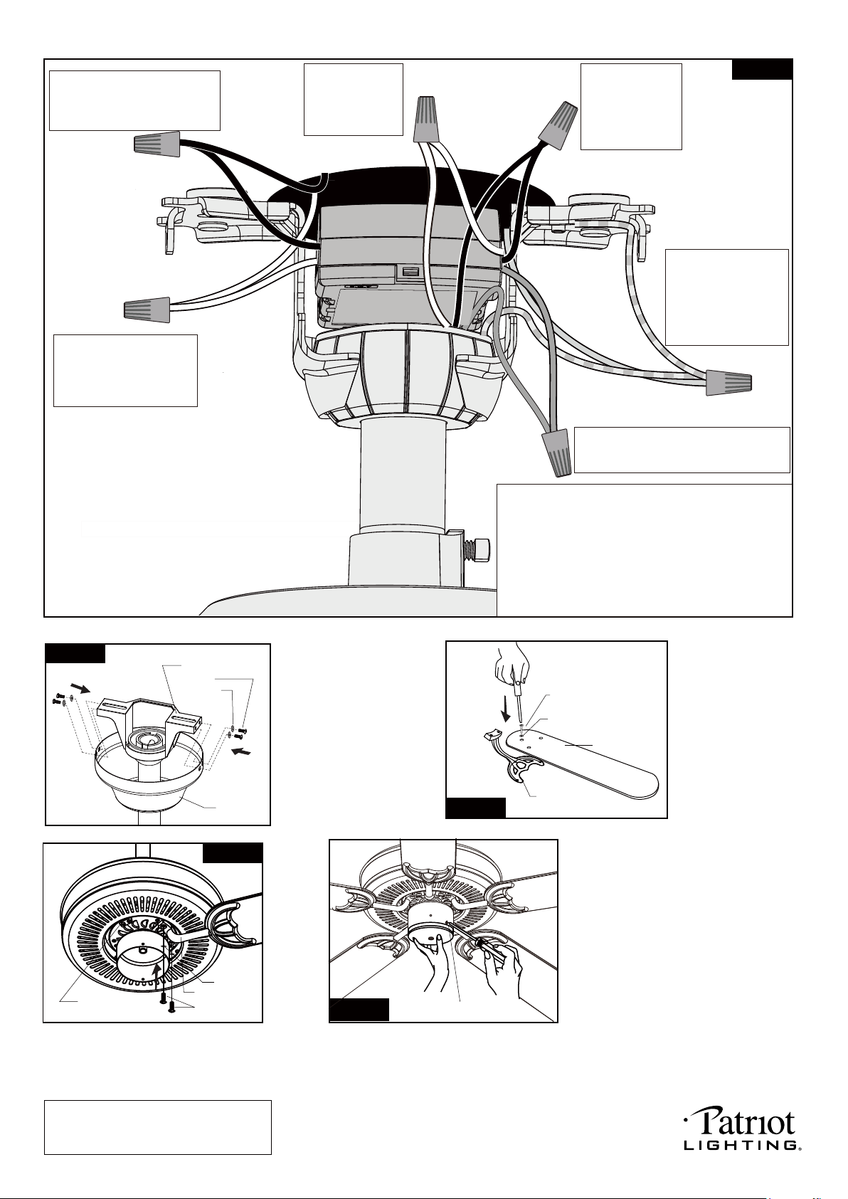
NOTE: Before installing blade
brackets to the motor, please
remove the plastic inserts.
Remove the motor screws and washers
from the motor assembly.
Secure blade brackets to the motor
with washers and motor screws.
Assembly without fan light
Remove the switch box screws
from the switch box cover first.
Make sure the lead wire of fan
light in switch box is sealed with
a wire connector. Secure the switch
box cover into fan fixture set with
the switch box screws.
Note: To install the fan light, skip this
step and proceed to Fig.17.
PAGE: 7 / 12
Motor Screw
Blade Bracket
Plastic Insert
Fig.15
Washer
Grounding
Green
Green
Black
Black
Black
Black
Connect the white
wire from receiver
to the white wire
from motor with a
wire connector.
Connect the black
wire from receiver
to the black wire
from motor (This is
for fan control) with
a wire connector.
White
White
White
White
Blue
Blue
(For downrod mount only):
Hang the fan on hanger
bracket, and make sure
the slot of hanger ball is
snapped into the chip of
hanger bracket exactly.
Note: For slope ceiling
installation, make sure the
slot of hanger ball and the
chip of hanger bracket
face down.
Connect the blue wire from receiver to the
blue wire from motor (This is for light
control) with a wire connector.
Connect three
ground wires (Green,
or bare copper) coming
from outlet box,
downrod and hanging
bracket with a wire
connector.
Screw
Hanger Bracket
Washer
Canopy
Fig.13
Tighten blades to
blade brackets by
using blade screws
and washers.
Blade Screw
Washer
Blade
Blade Bracket
Fig.14
Connect the white (neutral)
wire from receiver to the
white (neutral) wire from the
outlet box with a wire
connector.
Connect the black (hot) wire
from receiver to the black (hot)
wire from outlet box with a wire
connector.
*** The wire connection points should be turned upward
and pushed carefully up into outlet box.
*** After making the wire connections, the wires should
be spread apart. The white (neutral) conductor from
receiver and outlet box with green (grounding)
conductor on one side; the black (hot) conductor
from receiver and outlet box with the white, black
and blue conductor from receiver and motor on the
other side of the outlet box.
Fig.16
Switch Box Screw
Fig.12
220104
PAGE: 8 / 12
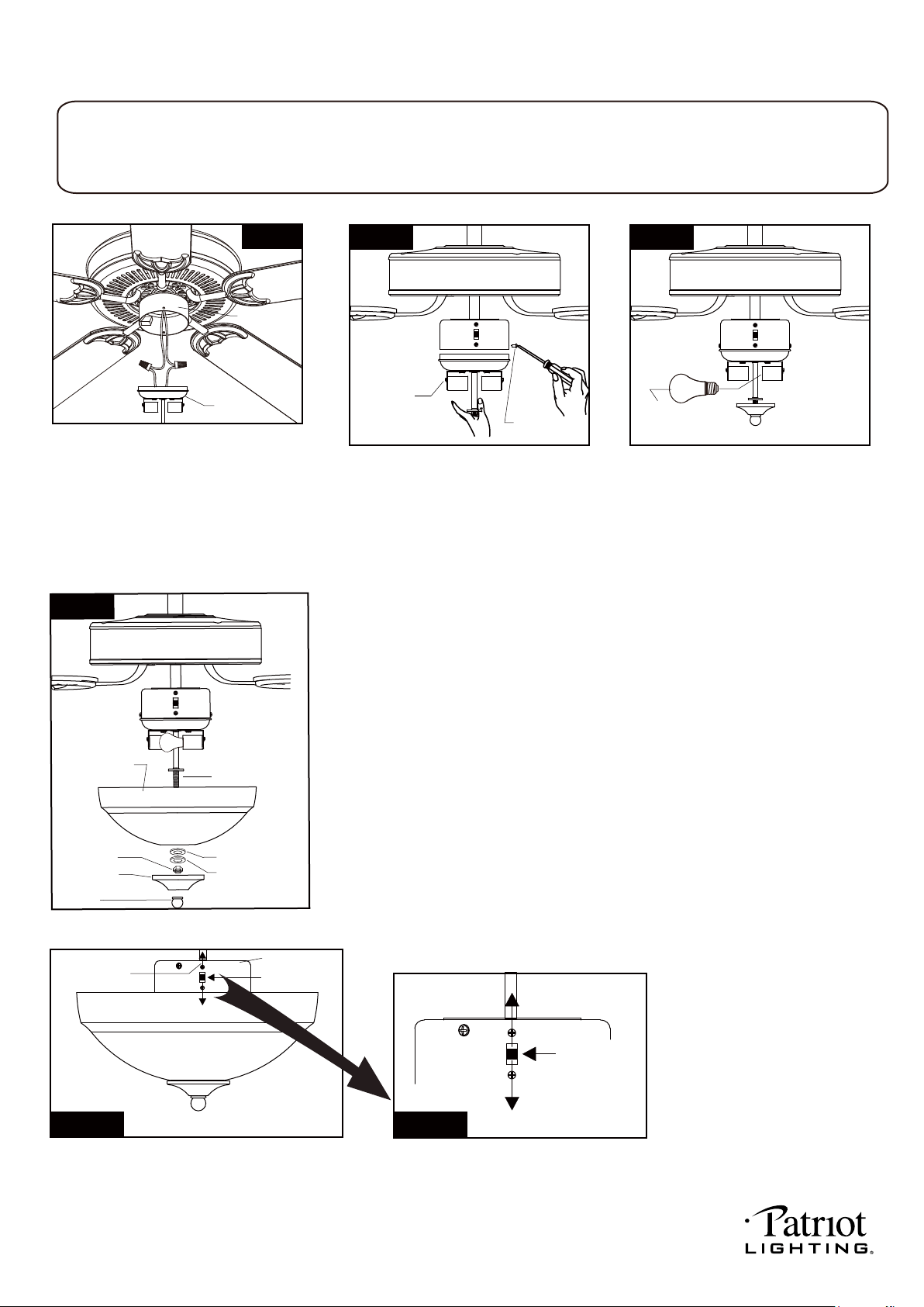
The slide switch on switch box sets direction of fan rotation. Select the desired direction of fan rotation.
Push the slide switch down for "Forward" and up for "Reverse".
Note: Wait for fan to stop before reversing the direction of blade rotation.
Slide Switch
Reverse
Forward
Fig.21-a Fig.21-b
Slide Switch
Switch Box
Reverse
Forward
End Cap
Finial
Rubber Washer
Metal Washer
Hex Nut
Glass Shade
Fig.20
Remove the switch box cover screws
from the switch box cover first.
Carefully put the wires into the fan
fixture set, then attach the fan light
into the fan fixture set with the switch
box screws.
Install LED bulbs (included).
WARNING: Do not press dimmable
button of remote control when
using compact fluorescent bulbs
(CFL) and non-dimmable LED bulbs.
Install fan light (Provided with package)
Connect wires:
The white (neutral) wire from the fan
light to white (neutral) wire from fan
fixture set with a wire connector.
The black (hot) wire from fan light to
blue (hot) wire from fan fixture set with
a wire connector.
Fan Light
Fan Fixture
Set
Fig.17
2-9W E26 A19 LED
Bulbs (included)
E26 A19 bulbs Max.60W
Fig.19Fig.18
Switch Box
Screw
Fan Light
WARNING:
This fan light has a built-in current limiting device in the receiver of remote control to conserve energy. The fan light
Install fan light
Threaded Pipe
Remove the finial, end cap, hex nut, metal washer and rubber washer
from threaded pipe first. Install the glass shade, rubber washer and metal
washer upward through the threaded pipe and secure with hex nut. Then
attach the end cap to the glass shade and secure it with finial.
will shuts off shortly if the combined wattage of the installed bulbs exceeds 190Watts. Please replace light bulbs
with lower wattage bulbs which show on relamping label or package and then turn on the fan light again.
220104
PAGE: 9 / 12
Install Without Remote Controller
Turn OFF the electric circuit at the main fuse or circuit breaker box. (See Fig.25)
Unscrew the canopy. Remove the wire connectors from the fan to ceiling
wire connection. The receiver should be removed from the hanger bracket.
(See Fig. 26)
Note: Remote controller can not be used along with a solid-state speed control at the same time.
Turn ON the electric circuit at the
main fuse or circuit breaker box.
Install the battery (9V, included) into the transmitter.
* Press "HI" button to turn on the fan at high speed.
* Press "MED" button to turn the fan in medium speed.
* Press "LOW" button to turn the fan in low speed.
* Press "FAN OFF" button to turn off the fan.
* Press "LIGHT ON /OFF" button to turn on or turn off
the light.
* Press and hold the "DIMMER" button to dim or brighten
lights to the desired level and release, and the
brightness level will be memorized. Turn on the light
again, then fan light will be restored to the
brightness-level at which it was dimmed last time.
Note:
1. This remote controller has a memory function
setting. The fan will operate at the same speed
and the fan light will stay at the same
brightness-level as the last time the power
supply was turned off.
2. Compatible Wall Switches:
Menards SKU# 363-2615 / 363-5815.
3. Compatible with E26 (M) base dimmable
LED bulb: Menards SKU# 353-8101.
Install the transmitter wall bracket on the wall with two screws
and place transmitter in it carefully.
HI
MED
LOW
FAN OFF
DIMMERLIGHT
ON/OFF
Transmitter
Wall Bracket
Screw
Fig.24
Fig.26
Fig.25
Fig.22
Fig.23
Receiver
Hanger Bracket
Canopy
220104
PAGE:10 / 12
Connect the white (neutral)
wire from motor to the white
(neutral) wire from the
outlet box with a wire
connector.
Connect the black (hot) wire
(This is for fan control) and blue
wire (This is for light control) from
motor to the black (hot) wire from
outlet box with a wire connector.
Bla
Black
ck
Blue
Green
White
White
Grounding
Green
*** After making the wire connections, the wires should
be spread apart. The white (neutral) conductor and
green (grounding) conductor on one side and the
black (hot) conductor and blue (light) conductor on
the other side of the outlet box.
*** The wire connection points should be turned upward
and pushed carefully up into outlet box.
Connect three
ground wires (Green
or bare copper) coming
from outlet box,
downrod and hanging
bracket with a wire
connector.
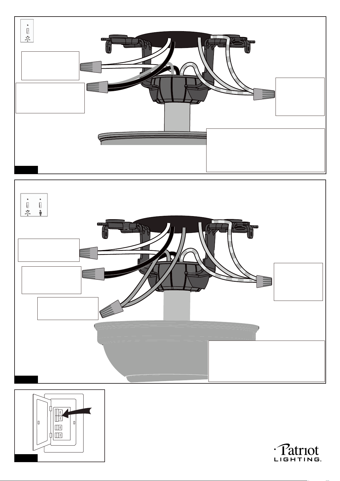
For a single switch
Follow these steps:
Connect three
ground wires (Green
or bare copper) coming
from outlet box,
downrod and hanging
bracket with a wire
connector.
Connect the black (hot) wire
from motor (This is for fan
control) to the black (hot)
wire from outlet box with a
wire connector .
Green
Black
Blue
Green
White
Black
Blue
(light)
White
Grounding
Connect the white (neutral)
wire from motor to the white
(neutral) wire from outlet box
with a wire connector .
Connect the blue wire (This
is for light control) from motor
to the blue wire from outlet
box with a wire connector.
*** The wire connection points should be turned
upward and pushed carefully up into outlet box.
Turn ON the electric circuit at the main fuse or circuit breaker box.
For dual switches
Follow these steps:
*** After making the wire connections, the wires should
be spread apart. The white (neutral) conductor and
green (grounding) conductor on one side and the
black (hot) conductor and blue (light) conductor on
the other side of the outlet box.
Fig.27
Fig.28
Fig.29
220104
PAGE: 11 / 12
Troubleshooting Guide
If you have difficulty operating your new ceiling fan, it may be the result of incorrect assembly, installation
or wiring. If you experience any faults, please check this Troubleshooting Guide. If a problem cannot be
remedied or you are experiencing difficulty in installation, please call our Customer Service Department
(1-800-887-6326).
PROBLEM
1. If fan does not start:
2. If fan sounds noisy:
3. If fan wobbles:
4. If light does not work:
1. Check main and branch circuit fuses or circuit breakers.
2. Make sure forward/reverse switch is firmly in bottom or top position. Fan will not
operate when switch is in the middle.
3. Make sure that the wall control is turned "ON".
4. Check line wire connections to fan and switch wire connections in switch box.
CAUTION: Make sure main power is turned off.
1. Make sure all screws in motor housing are snug. (not over tightened)
2. Make sure the screws which attach the fan blade bracket to the motor are tight.
3. Make sure wire connectors in switch box are not rattling against each
other or against the interior wall of the switch box.
CAUTION: Make sure main power is turned off before accessing switch box.
4. If using an optional ceiling fan light kit, make sure the screws securing
the glassware are finger tight. Make sure light bulb is tight in socket and
not touching glass shade(s). If vibration persists from glass, remove glass and
install a 1/4 in. wide rubber band on glass neck to act as an insulator. Replace
glass and tighten screws against rubber band.
5. Some fan motors are sensitive to signals from Solid State variable speed
controls. DO NOT USE a Solid State variable speed control.
6. Allow "break-in" period of 24 hours. Most noises associated with a new fan will
disappear after this period.
All blades are weighed and grouped by weight. Natural woods vary in density
which could cause the fan to wobble even though all blades are weight-matched.
The following procedures should eliminate most of the wobble. Check for wobble
after each step.
1. Check that all blades are screwed firmly into blade brackets.
2. Check that all blade brackets are tightened securely to motor.
3. Make sure that canopy and hanger bracket are tightened securely to ceiling
junction box and junction box is mounted firmly to ceiling joist.
4. Most wobble problems of fan are caused when blades are not in equal level. To
check the blade levels, select a point on the ceiling above the tip of any blade.
Measure the distance from the ceiling to the blade tip, to an accuracy of 1/8
inch. Rotate the blades until the next blade is in the measuring position. Repeat
measurement for each blade. If all blade levels are not equal, you can adjust
blade levels by the following procedure. To adjust a blade tip down, insert a
washer (not supplied) between the blade and blade bracket at the screw
closest to the motor. To adjust a blade tip up, insert washer (not supplied)
between the blade and blade bracket at the two screws farthest from the motor.
5. Interchanging two adjacent blades could redistribute the weight and possibly result
in smoother operation.
1. Check blue wire from fan to make sure it is connected to hot wire from supply wire
coming out of the ceiling.
2. Check for loose or disconnected wires in fan switch box.
3. Check for loose or disconnected wires in light kit.
4. Check for faulty light bulbs.
CAUTION: Make sure main circuit is turned off before entering switch box.
SUGGESTED REMEDY
220104
DYNAMIC BLADE BALANCING KIT
PREFACE
Your ceiling fan may sometimes have wobbling problems when operating due to irregularity in the
blades or the blade brackets. Improper assembly in the mounting system may cause some additional
problems. This balancing kit can be used to fix wobbling problems.
DYNAMIC BLADE BALANCING KIT FOR CEILING FANS
1. Make sure that all blades are firmly screwed into the blade brackets.
2. Make sure that all blade brackets are firmly secured to the motor housing.
3. By looking up at the fan from below, check and be certain that none of the blade brackets are bent
and that none of the blades are out of position.
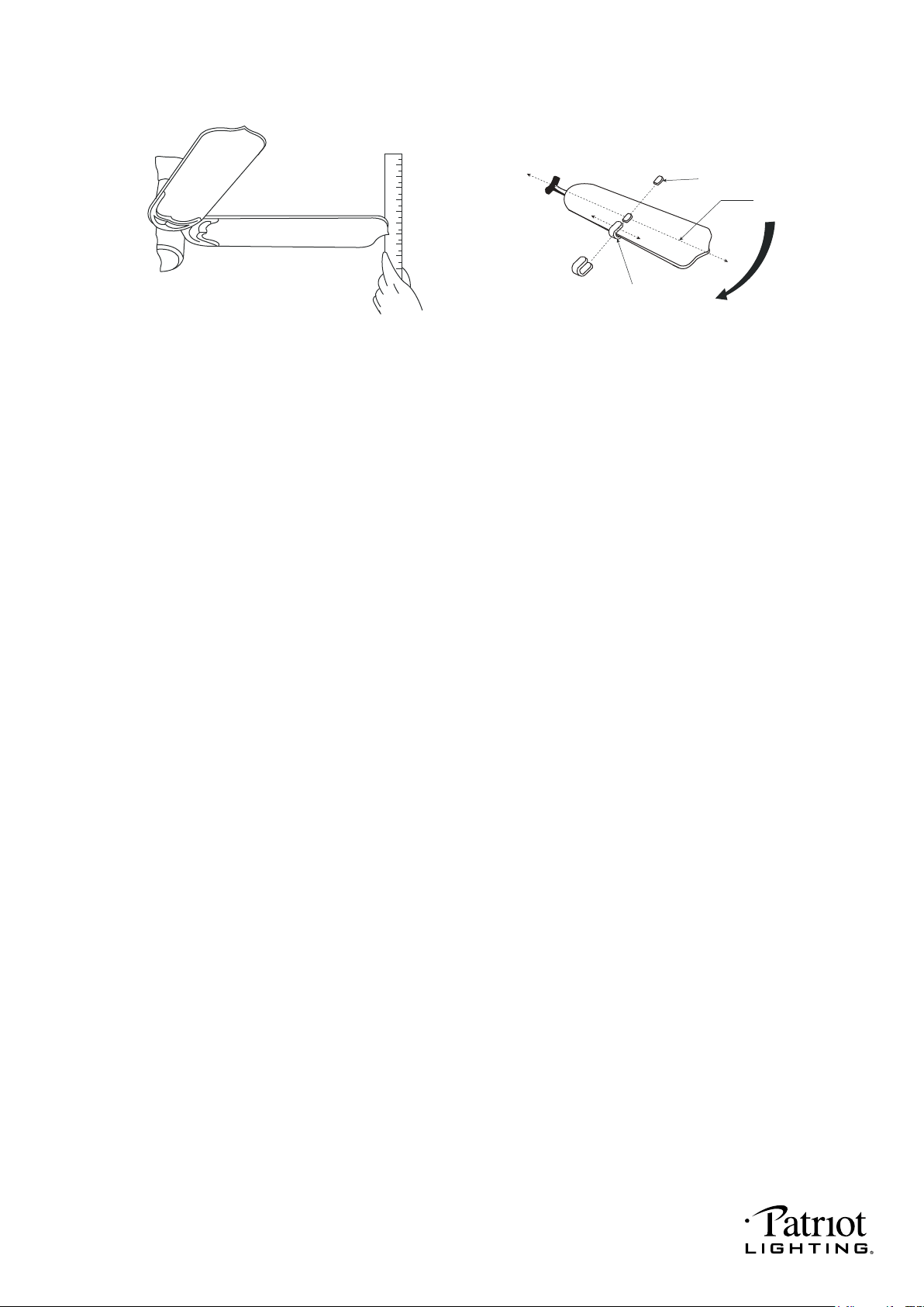
4. Use a yardstick to check the blade tracking. Put the yardstick up against the ceiling vertically and
against the outside leading edge of a blade. Note the distance of the edge of blade to the ceiling.
Carefully turn the blades slowly by hand to check the remaining blades. All distances should be
the same.
Operate the fan ten minutes. After following all the steps and if the wobbling problem is not solved, a
dynamic balancing needs to be done with balancing kit. Follow the procedure listed below:
● Turn the fan off. Select one blade and place the plastic clip on it, with the plastic clip located
halfway between the blade bracket and the blade tip on the edge of the blade.
Caution: The plastic clip should be placed on the windward edge of the blade for fear of
clip flying off.
● Turn the fan on (set the speed that causes the wobble most). Observe if the wobble is better or
worse. Turn the fan off and move the clip to the next blade. Do the same for all blades and note
on which blade the clip reduces the wobble most. Place the clip on the blade which showed the
most improvement. Move the clip inward and outward on this blade and operte the fan to find
the position where the clip gives the most improvement.
Caution: Stay clear of the blades. If the clip, for any reason, is not secure, injury could result.
● Once the exact position is determined, place a weight on the top of the blade, on its centerline and
as close as possible to the clip. Peel the paper off of the back of the weight and press firmly to
ensure that it is securely attached to the blade. Remove the clip.
Caution: Clean the surface of fan blade before placing the balancing weight so that the
balancing weight will be firmly attached to it.
BALANCING WEIGHT
MEASURING
POINT
YARDSTICK
PLASTIC CLIP
CENTERLINE
COUNTER-
CLOCKWISE
1
2
3
4
5
6
7
8
9
PAGE:
12 / 12
220104
