191225
Model No.: # 355-0706
PAGE: 1 / 10
PAGE: 2 / 10
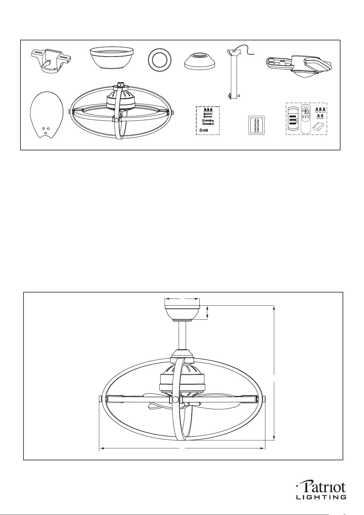
Unpack your fan and check the contents. You should have the following items.
1.) Hanger Bracket
2.) Canopy
3.) Canopy Cover (Comes in a separate bag)
4.) Downrod Stand Cover
5.) Downrod Set (Includes Hanger Ball, 6˝ Downrod, Hanger Pin & Lock Pin)
6.) Blade bracket Set
7.) Fan Blade (3 PCS)
8.) Fan Motor Assembly
9.) Assembly Kit
10.) Installation Instructions
11.) Remote Control Set (Includes Transmitter & Receiver & Wire Connector & Battery)
Package Contents:
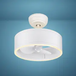
Dimension Reference (Installed with 6˝ Downrod):
A. 19-3/4˝ B. 22˝ C. 2˝ D. 5˝
1
2
3
4
5
6
7
8
9 10 11
X
1
0
9V
191225
A
B
C
D
PAGE: 3 / 10
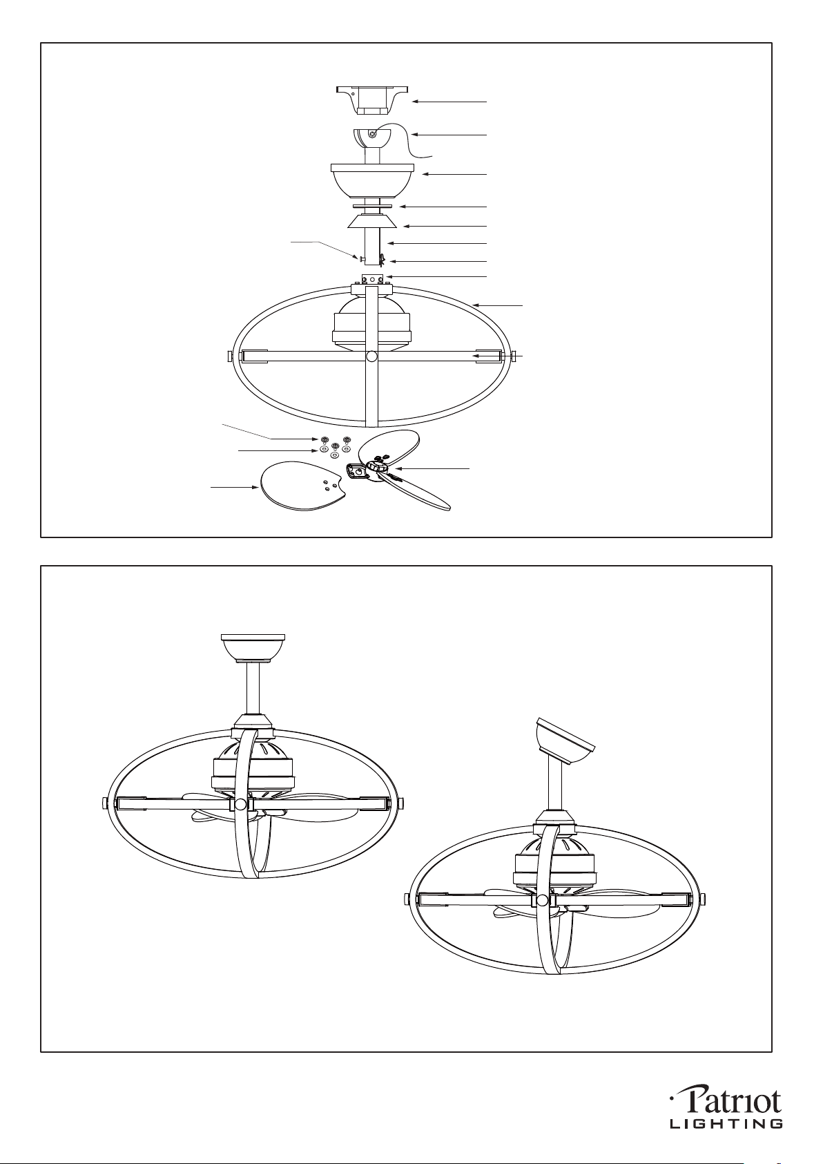
Downrod Mount
Slope Ceiling Mount (Up to 23 degrees)
Dual Mount Drawing
Exploded View Detail
191225
Blade Bracket Set
Washer Set
Screw Set
Blade
Hanger Bracket
Canopy
Canopy Cover
Downrod Stand Cover
Downrod
Hanger Ball
Collar
Lock Pin
Fan Motor Assembly
LED Strip Included
Hanger Pin
Safety Instructions
READ ALL SAFETY INFORMATION AND INSTALLATION INSTRUCTIONS BEFORE YOU BEGIN TO
INSTALL THE FAN AND SAVE INSTRUCTIONS.
All set screws of the fan must be checked and retightened where necessary before installation.
To reduce the risk of personal injury, do not bend the blade brackets when installing the brackets,
balancing the blades or cleaning the fan. Do not insert foreign objects between rotating fan blades.
Before changing the fan direction, turn off the fan and wait for the fan blades to stop completely.
The safeguards provided by these safety instructions and by the separate installation
instructions are not meant to cover all possible conditions and situations that may occur. It must be
understood that common sense, caution and care are factors which can not be built into this product.
These factors must be supplied by the person(s) installing, caring for and operating the fan.
TO AVOID RISK OF ELECTRIC SHOCK, BE SURE TO SHUT OFF POWER AT THE MAIN
FUSE OR CIRCUIT BREAKER BOX BEFORE INSTALLING OR SERVICING THIS
FIXTURE. TURNING OFF THE ELECTRICAL POWER BY USING THE LIGHT SWITCH
IS NOT SUFFICIENT TO PREVENT ELECTRICAL SHOCK.
TO REDUCE THE RISK OF INJURY, INSTALL THE FAN SO THAT THE BLADES ARE
AT LEAST 7 FEET (2.1 METERS) ABOVE THE FLOOR AND AT LEAST 18 INCHES
(0.5 METERS) FROM THE TIP OF THE BLADES TO THE WALL.
TO REDUCE THE RISK OF FIRE, ELECTRIC SHOCK, OR PERSONAL INJURY, MOUNT
TO OUTLET BOX MARKED "ACCEPTABLE FOR FAN SUPPORT" AND USE MOUNTING
SCREWS PROVIDED WITH THE OUTLET BOX.
THE INSTALLATION HAS TO BE IN ACCORDANCE WITH THE NATIONAL ELECTRICAL
CODE, ANSI/NFPA 70-1999 AND LOCAL CODES. IF YOU ARE UNFAMILIAR WITH THE
METHODS OF INSTALLING ELECTRICAL WIRING, SEEK THE SERVICES OF A
QUALIFIED LICENSED ELECTRICIAN.
WARNING
PAGE: 4 / 10
191225
PAGE: 5 / 10
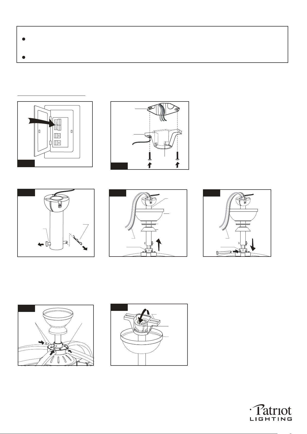
Installation Steps :
INSTALLATION INSTRUCTIONS
IMPORTANT:
BEFORE YOU BEGIN INSTALLING THE FAN, CAREFULLY READ ALL INFORMATION IN
SAVE ALL INSTRUCTIONS.
NOTE: The fan weight is 15.87 lbs (7.2 kg). Be sure the outlet box you are using is securely attached to the building
structure and can support the full weight of the fan. Failure to do so can result in serious injury.
Hanger Pin
Lock Pin
Remove the Lock Pin and take off
the Hanger Pin.
Fig.3
Loosen the collar screws out part way.
Insert the Downrod into the Collar.
Slide Hanger Pin through holes of
Collar and Downrod.
Tighten the two Collar Screws.
Slide Lock Pin into Hanger
Pin until it is locked into position.
Slide canopy, canopy cover (Making
Hang fan on hanger bracket, and rotate the downrod until the chip on
the hanger bracket snaps into the slot on the hanger ball.
Note: For slope ceiling installation, make sure the slot of hanger
ball and the chip of hanger bracket are toward the floor.
Slot
Chip
Hanger Bracket
Fig.7
Tighten the hanger bracket to the outlet
box with 2 mounting screws. (To reduce
the risk of fire, electric shock, or personal
injury, mount to the outlet box marked
"Acceptable for fan support" and use
mounting screws provided with the outlet
box.)
Note: For slope ceiling installation, make
sure that the chip of the hanger bracket
is toward the floor.
Fig.1
Turn OFF the electric circuit at the
main fuse or circuit breaker box.
Hanger
Bracket
Fig.2
Outlet Box
Chip
Fig.4
Motor Wires
Collar
Downrod
Canopy
Canopy Cover
Downrod Stand
Cover
THE SAFETY
INSTRUCTIONS AND INSTALLATION INSTRUCTIONS. IF IN DOUBT, CONSULT A QUALIFIED
ELECTRICIAN.
sure the smooth side of canopy cover
is facing downward.), and downrod
stand cover onto downrod, as shown;
then thread motor wires through
downrod.
191225
Fig.5
Motor Wires
Collar
Fig.6
Lock Pin
Collar
Screws
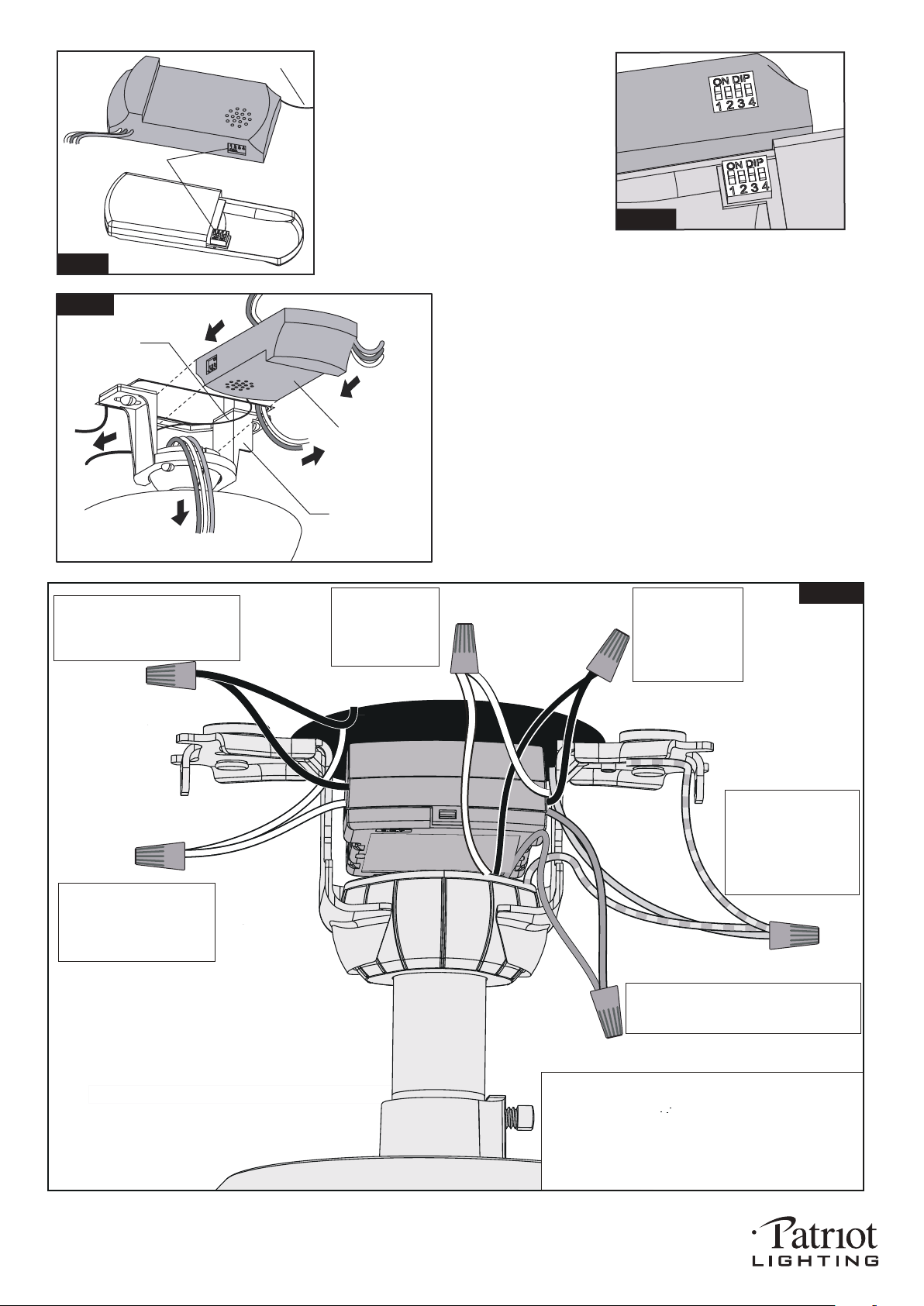
Fig.9
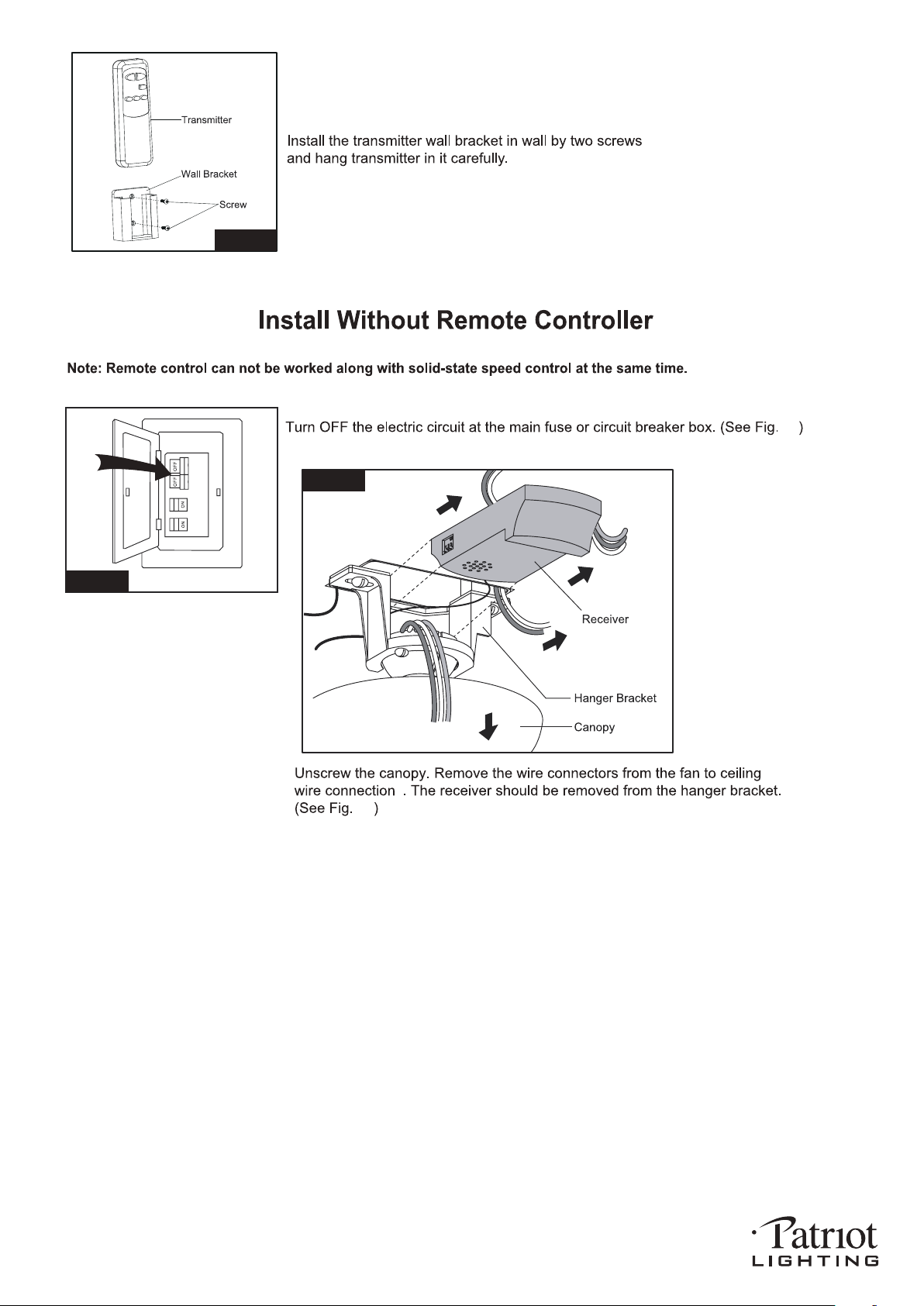
Move Ground Wires (a), Outlet Box wires (b), and
Motor Wires (c) away from the center of the Hanger
Bracket. Then slide Receiver through Hanger
Bracket as shown, Antenna end first, until it is
centered. Finally, cut Motor Wires (c) to length
needed for connections.
Antenna
Receiver
Hanger Bracket
a.
b.
c.
PAGE: 6 / 10
Code example:
1-ON 2-OFF 3-ON 4-OFF on both DIP
Switches.
Note: If you have two ceiling fans
with 2 remote control units, set 2
different codes for each set of
transmitter / receivers.
Fig.8a
Fig.8
Antenna
DIP Switch
Transmitter
Receiver
There is a code switch in the transmitter
and receiver. This "DIP Switch" is a 4 key
unit (Fig.8). All keys were set at "ON"
position in the beginning. Set the keys to
a different code. Make sure the same
numbered keys are switched "ON" for
both DIP Switches (Fig.8a). Take note
that the "ON" position may have different
orientation in each.
Grounding
Green
Green
Black
Black
Black
Black
Connect the white
wire from Receiver
to the white wire
from motor with a
wire connector.
Connect the black
wire from Receiver
to the black wire
from motor (This is
for fan control) with
a wire connector.
White
White
White
White
Blue
Blue
Connect the blue wire from receiver to the
blue wire from motor (This is for light
control) with a wire connector.
Connect three
ground wires (green,
or bare copper) coming
from outlet box,
downrod and hanging
bracket with a wire
connector.
Connect the white (neutral)
wire from receiver to the
white (neutral) wire from the
outlet box with a wire
connector.
Connect the black (hot) wire
from receiver to the black (hot)
wire from outlet box with a wire
connector.
*** The wire connection points should be turned upward
and pushed carefully up into outlet box.
*** After making the wire connections, the wires should
be spread apart. The white (neutral) conductor and
green (grounding) conductor on one side and the
black (hot) conductor and blue (light) conductor on
the other side of the outlet box.
Fig.10
191225
PAGE: 7 / 10
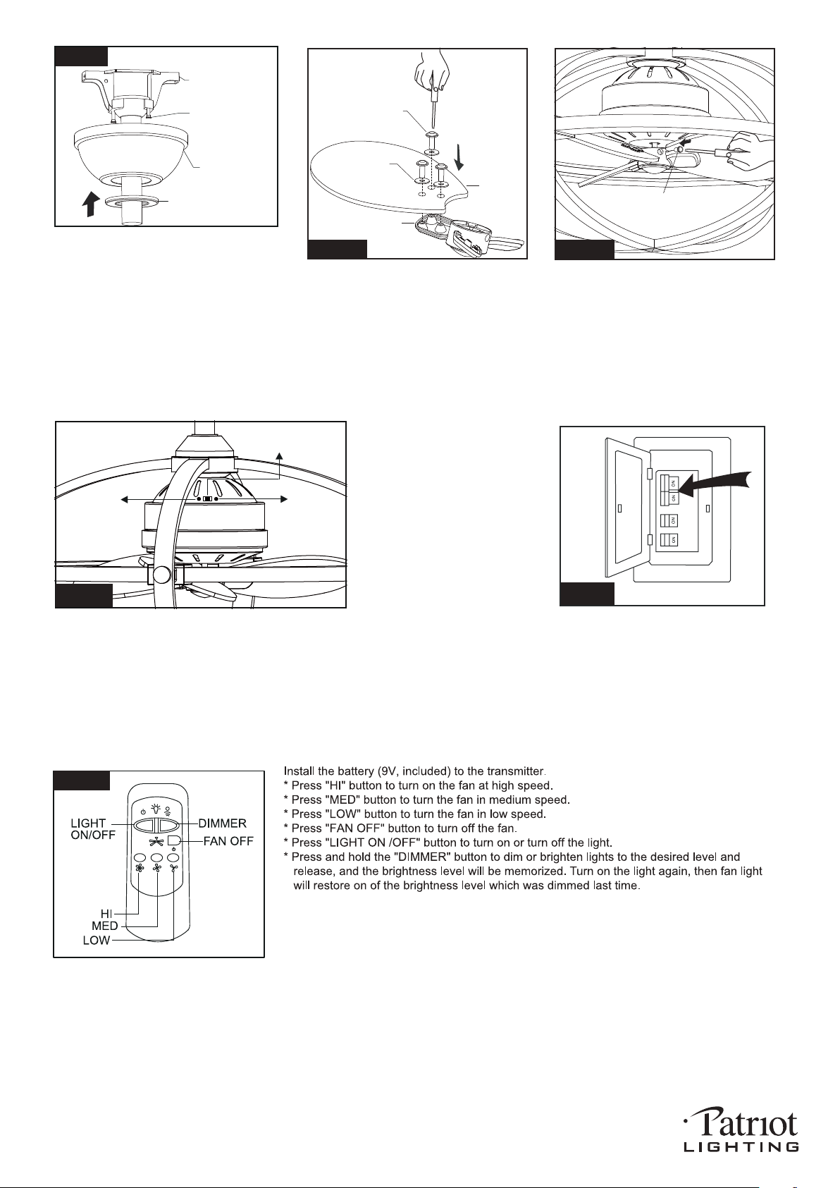
Slide the canopy up to ceiling and over
the two canopy screws on hanger
bracket. Rotate canopy clockwise, next,
while holding the canopy with one hand,
slide the canopy cover over the screws
and rotate clockwise until tight.
Note: Adjust the canopy screws as
necessary until the canopy and
canopy cover are snug.
Fig.11
Canopy Screw
Hanger Bracket
Canopy
Canopy Cover
Thread the blade screws through the
washer and blade into the blade bracket.
Tighten all blade screws securely.
Repeat to other blades.
Turn ON the electric circuit at the
main fuse or circuit breaker box.
191225
Fig.12
Blade Screw
Washer
Blade Bracket Set
Blade
Insert the blade bracket set onto the
fan motor assembly, then secure
them together by two blade bracket
set screws.
Slide Switch
Reverse
Forward
Fig.14
The slide switch on fan motor assembly sets direction of fan rotation.
Select the desired direction of fan rotation. Push the slide
switch left for " Forward" and right for "Reverse".
Note: Wait for fan to stop before reversing the direction
of blade rotation.
Blade Bracket Set Screw
Fig.13
Fig.15
Fig.16
Note:
1. This remote controller has memory function setting. The fan will operate at the same
speed and the fan light will stay at the same brightness as the last time the power supply
was turned off.
2. Compatible Wall Switch model no.:LUTRON / SKYLAPR / SFSQ-LFH-WH, the wall switch
only can turn on or turn off the light, but can not control dimming. Install Without Remote
Controller Fig.18.
PAGE: 8 / 10
Fig.17
Fig.18
Fig.19
18
19
191225
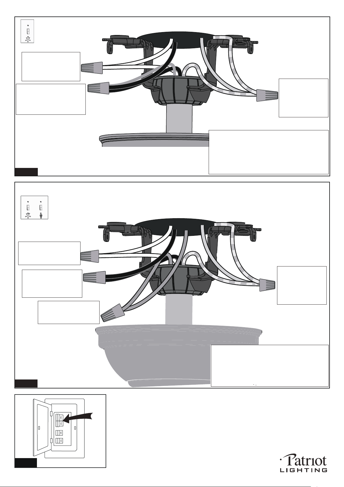
Fig.20
Connect the white (neutral)
wire from motor to the white
(neutral) wire from the
outlet box with a wire
connector.
Connect the black (hot) wire
(This is for fan control) and blue
wire (This is for light control) from
motor to the black (hot) wire from
outlet box with a wire connector.
Bla
Black
ck
Blue
Green
White
White
Grounding
Green
*** After making the wire connections, the wires should
be spread apart. The white (neutral) conductor and
green (grounding) conductor on one side and the
black (hot) conductor and blue (light) conductor on
the other side of the outlet box.
*** The wire connection points should be turned upward
and pushed carefully up into outlet box.
Connect three
ground wires (Green
or bare copper) coming
from outlet box,
downrod and hanging
bracket with a wire
connector.
For a single switch
Follow these steps:
Connect three
ground wires (Green
or bare copper) coming
from outlet box,
downrod and hanging
bracket with a wire
connector.
Connect the black (hot) wire
from motor (This is for fan
control) to the black (hot)
wire from outlet box with a
wire connector.
Green
Black
Blue
Green
White
Black
Blue
(light)
White
Grounding
Connect the white (neutral)
wire from motor to the white
(neutral) wire from outlet box
with a wire connector.
Connect the blue wire (This
is for light control) from motor
to the blue wire from outlet
box with a wire connector.
*** The wire connection points should be turned
upward and pushed carefully up into outlet box.
Fig.22
Turn ON the electric circuit at the main fuse or circuit breaker box.
For dual switches
Follow these steps:
*** After making the wire connections, the wires should
be spread apart. The white (neutral) conductor and
green (grounding) conductor on one side and the
black (hot) conductor and blue (light) conductor on
the other side of the outlet box.
PAGE: 9 / 10
Fig.21
191225

PAGE: 10 / 10
Trouble shooting Guide
If you have difficulty operating your new ceiling fan, it may be the result of incorrect assembly, installation
or wiring. In some cases, these installation errors may be mistaken for defects. If you experience any faults,
please check this Trouble shooting Guide. If a problem cannot be remedied or you are experiencing difficulty
in installation, please call our Customer Service Department.
PROBLEM
1. If fan does not start:
2. If fan sounds noisy:
3. If fan wobbles:
4. If light does not work:
1. Check main and branch circuit fuses or circuit breakers.
2. Check line wire connections to fan and switch wire connections in switch
housing.
CAUTION: Make sure main power is turned off.
3. Make sure forward/reverse switch is firmly in left or right position. Fan will not
operate when switch is in the middle.
4. Make sure that the wall control is turned "ON".
1. Make sure all screws in motor housing are snug. (not over tightened)
2. Make sure the screws which attach the fan blade bracket to the motor are tight.
3. Make sure wire connectors in switch housing are not rattling against each
other or against the interior wall of the switch housing.
CAUTION: Make sure main power is turned off before accessing switch housing.
4. If using an optional ceiling fan light kit, check to be sure the screws securing
the glassware are finger tight. Check to be sure light bulb is tight in socket and
not touching glass shade(s). If vibration persists from glass, remove glass and
install a 1/4 in. wide rubber band on glass neck to act as an insulator. Replace
glass and tighten screws against rubber band.
5. Some fan motors are sensitive to signals from Solid State variable speed
controls. DO NOT USE a Solid State variable speed control.
6. Allow "break-in" period of 24 hours. Most noises associated with a new fan will
disappear after this period.
All blades are weighed and grouped by weight. Natural woods vary in density
which could cause the fan to wobble even though all blades are weight-matched.
The following procedures should eliminate most of the wobble. Check for wobble
after each step.
1. Check that all blades are screwed firmly into blade beackets.
2. Check that all blade brackets are tightened securely to motor.
3. Make sure that canopy and mounting bracket are tightened securely to ceiling
junction box and junction box is mounted firmly to ceiling joist.
1. Check blue wire from fan to make sure it is connected to hot wire from house.
2. Check for loose or disconnected wires in fan switch housing.
3. Check for loose or disconnected wires in light kit.
4. Check for faulty light bulbs.
CAUTION: Make sure main power is turned off before accessing switch housing.
SUGGESTED REMEDY
191225