220104
X 16
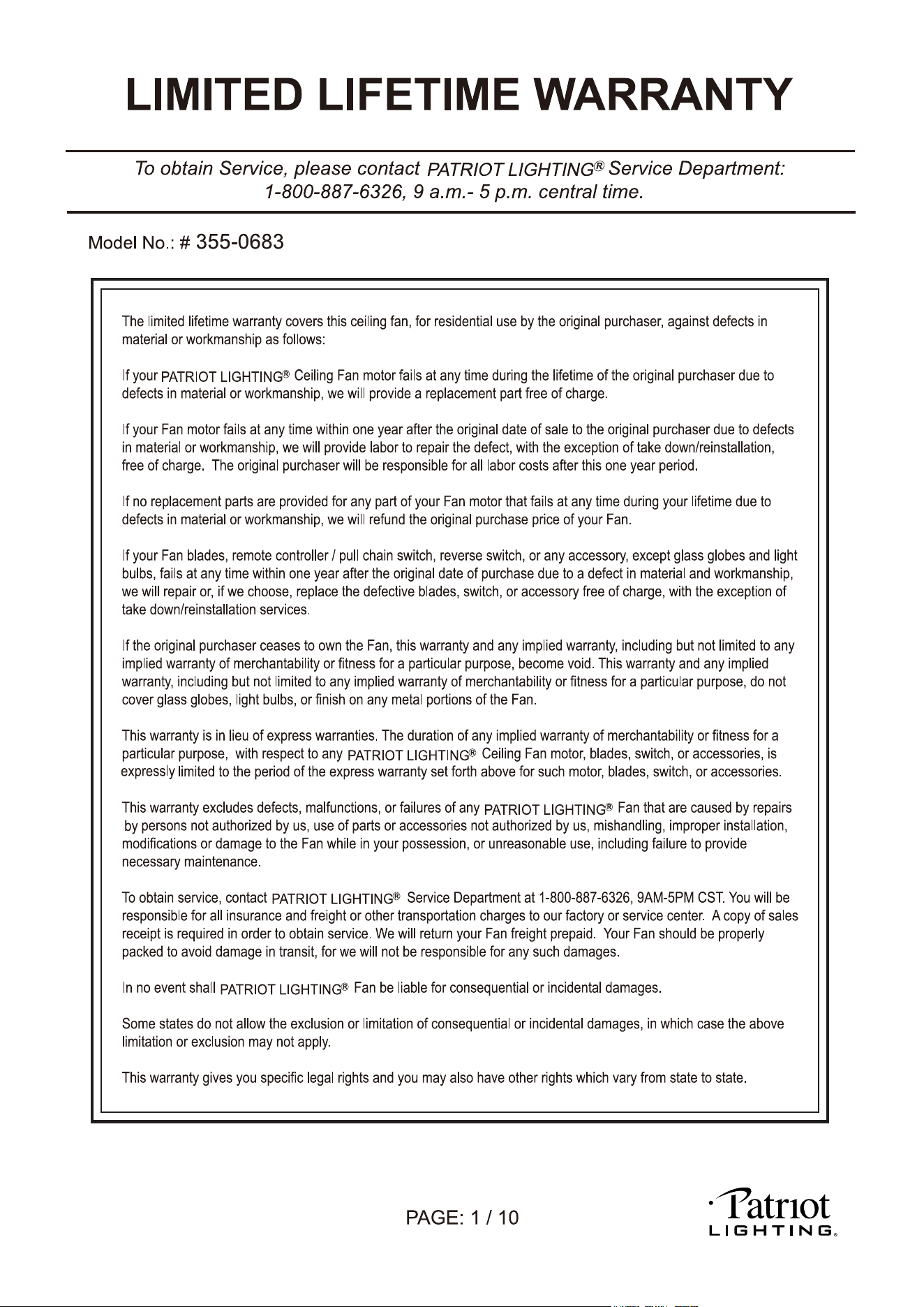
Dimension Reference (Installed with 6" Downrod):
F
A. 20" B. 12-1/4" C. 2-3/8" D. 10-1/8" E. 5-1/8" F: 42"
(Remove the Preassembled Canopy Cover from the Canopy Before Installation.)
220104
220104
4
220104
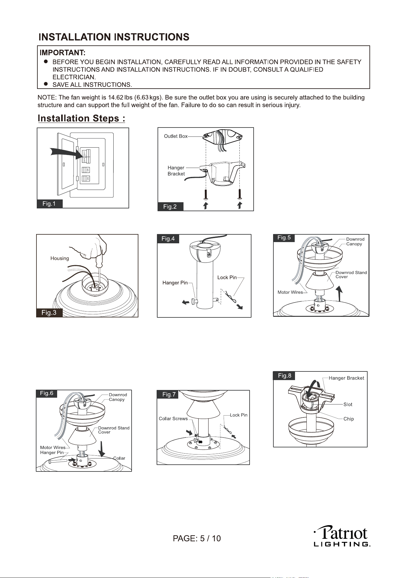
Tighten the two collar screws.
Slide lock pin into hanger pin
until it is locked into position.
Hang the fan on hanger bracket,
and make sure the slot of hanger
ball is snapped into the chip of
hanger bracket exactly.
Note: For sloped ceiling installation
make sure the slot of hanger ball
and the chip of hanger bracket
face down.
Loosen the collar screws out part
way.
Insert the downrod into the
collar. Slide hanger pin through
holes of collar and downrod.
Thread the motor wires through
the downrod stand cover, canopy
cover (Making sure the smooth
side of canopy cover is facing
downward.), canopy and downrod.
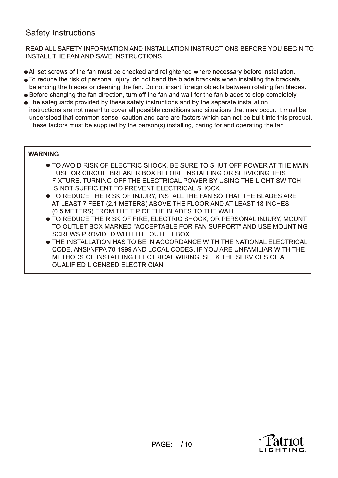
Tighten the hanger bracket to the outlet box
with two mounting screws. (To reduce the
risk of fire, electric shock, or personal injury,
mount to an outlet box marked "Acceptable
for fan support" and use mounting screws
provided with the outlet box.)
Note: For sloped ceiling installation, make
sure that the chip of the hanger bracket
is toward the floor.
Turn OFF the electric circuit at the
main fuse or circuit breaker box.
Remove the lock pin and take
off the hanger pin.
(For ceiling mount only)
Remove the canopy cover from the
canopy. Remove three of six screws
(every other one screw) securing the motor
collar to the top of the fan motor housing.
Attach the canopy to the housing with three
screws.
Go to Fig.9 for the next step.
Canopy Cover
220104
220104
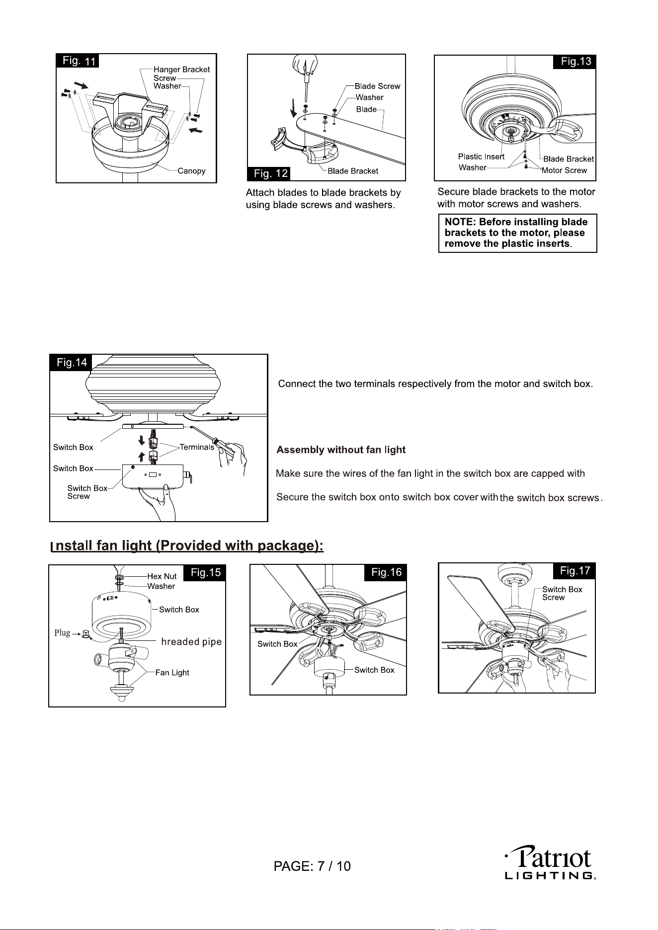
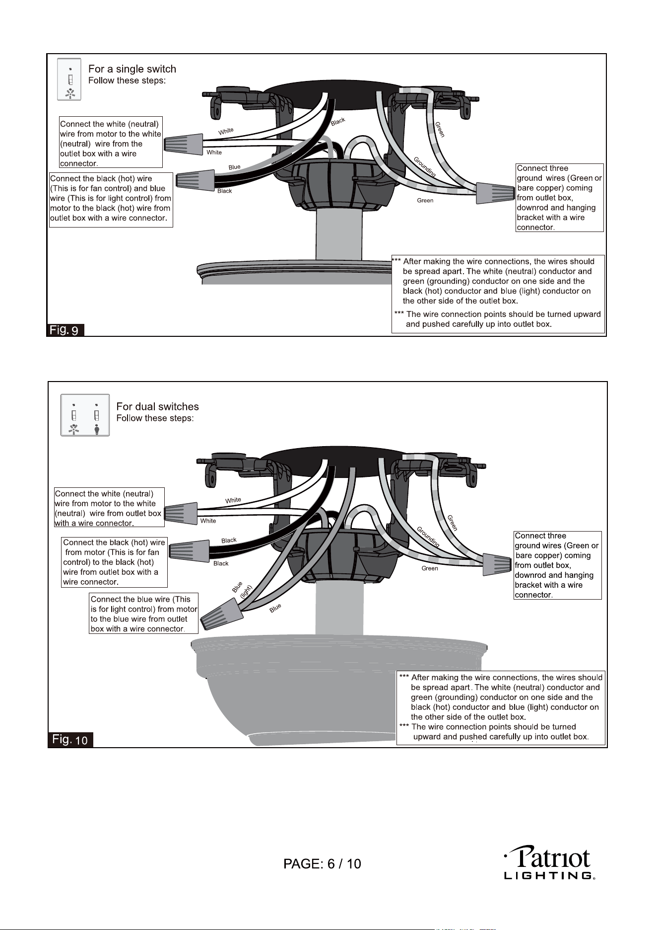
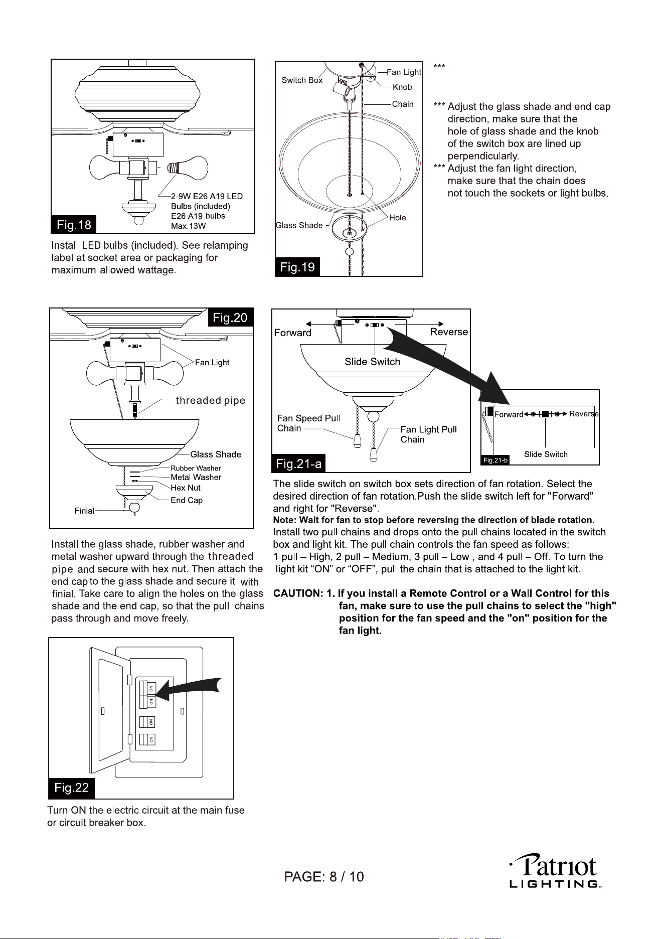
Note: To install the fan light, skip this step and proceed to Fig.15.
wire connectors.
Cover
Remove screws from switch box cover first .
T
Remove the plug from the switch box.
Remove the nut and lock washer from fan
light. Attach the fan light to the switch box
by threading the fan light wires (black and
white) and remove threaded pipe through
the hole of switch box and then secure
them onto the switch box with hex nut &
washer. Be sure it is tight enough to prevent
light kit from vibrating loose.
Connect wires:
--- Remove screws from switch box cover
first.
--- Connect the male terminal from switch
box cover and female terminal from the
switch box.
--- The blue (hot) wire from the switch box
cover to the black (hot) wire from fan light.
--- The white (neutral) wire from the switch
box cover to the white (neutral) wire from
fan light.
Carefully put the wires into the switch box.
Then connect the two terminals respectively
from the motor and the switch box.
Cover
Secure the switch box onto switch box
cover with the switch box screws.
There are four hanger bracket screws
and lock washers.
Remove two screws and lock washers
from the hanger bracket (one from
each side) and loosen the other two
remaining screws. Align the "L shaped"
slots of the canopy with the two
remaining screws on the hanger bracket
and push the canopy upwards to engage
the slots and turn clockwise to lock in place.
Tighten the screws and install the other two
hanger bracket screws and lock washers
into the remaining holes of the canopy and tighten.
220104
2. Compatible Wall Switches:
Menards SKU# 363-2615 / 363-5815.
Remove the finial, end cap, hex
nut, metal washer and rubber
washer from fan light first.
220104
box.
box
box.
box.
box.
box.
220104
PAGE: 10 / 10
220104
