PAGE: 1 / 11
220104
PAGE: 2 / 11
X 16
Remote
Control
Instructions
3
1
2 4 5
6
7 8 9
10
11 12 13 14 15
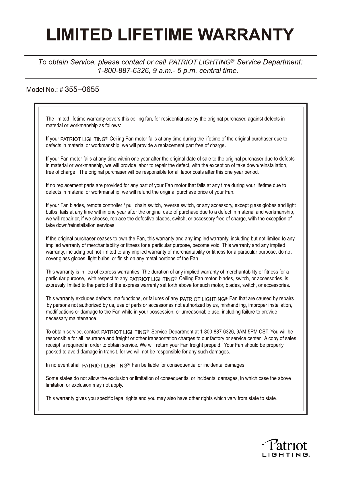
Unpack your fan and check the contents. You should have the following items.
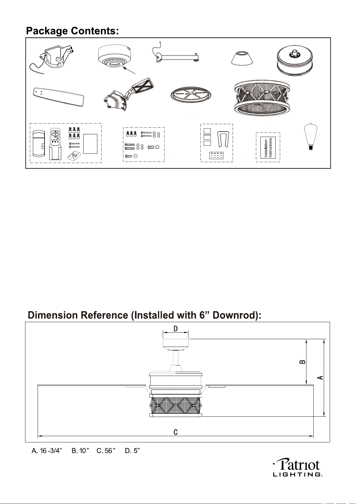
1.) Hanger Bracket
2.) Canopy
3.) Decorative Cap (Remove the Preassembled Decorative Cap from the Canopy Before Installation.)
4.) Downrod Set (Included Hanger Ball, 6” Downrod, Hanger Pin & Lock Pin)
5.) Downrod Stand Cover
6.) Fan Motor Assembly
7.) Fan Blades (5 PCS)
8.) Blade Brackets (5 PCS)
9.) Connect Plate of Light Kit
10.) Light Kit
11.) Remote Control Set (Includes Receiver & Transmitter & Wire Connectors & Battery
& Screws & Remote Control Instructions)
12.) Assembly Kit
13.) Blade Balancing Kit
14.) Installation Instructions
15.) 5W E12 (C) Base ST15 Type LED Bulb (2pcs)
220104
PAGE: 3 / 11
Decorative Cap
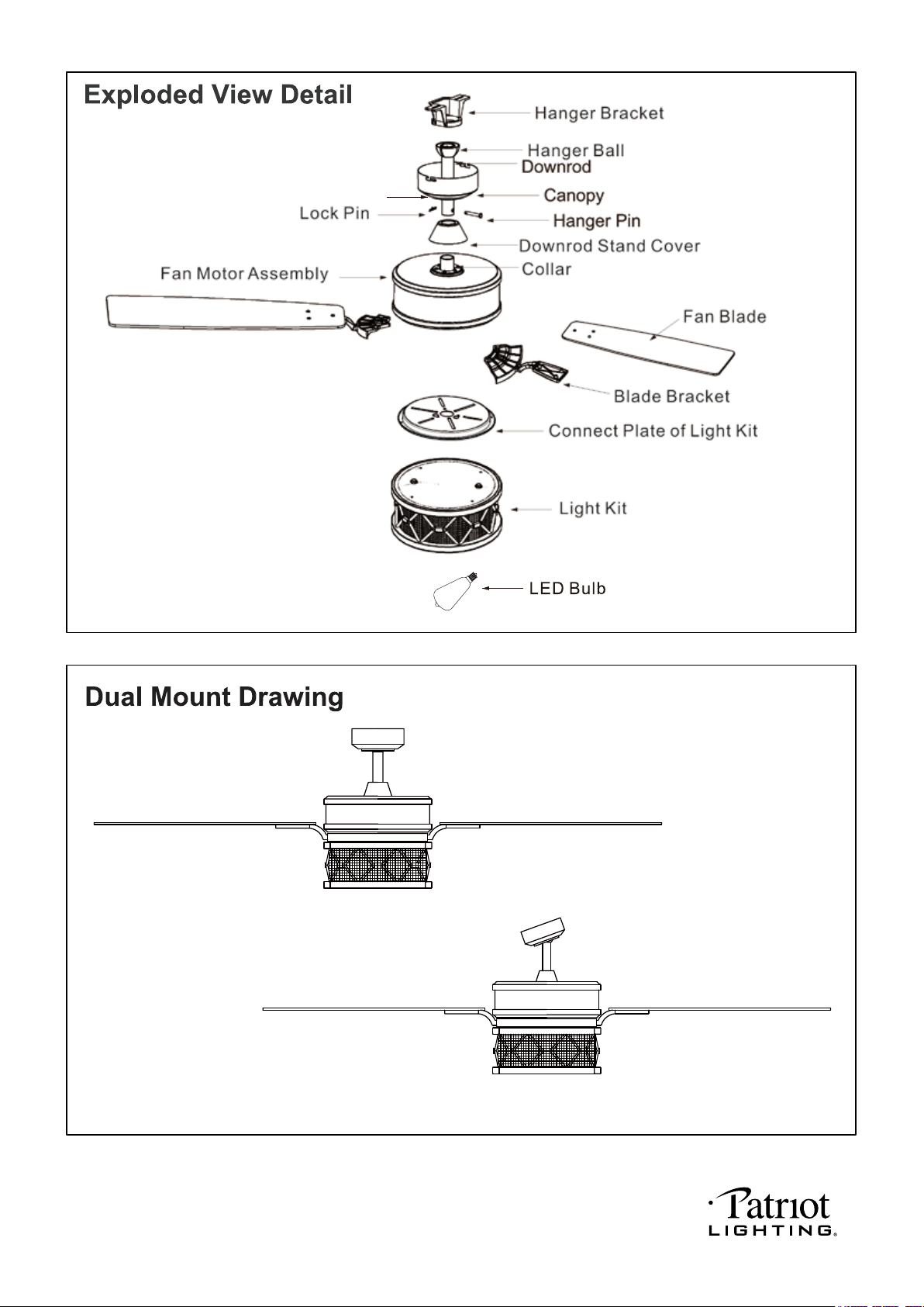
Downrod Mount
Sloped Ceiling Mount (Up to 23 degrees)
220104
PAGE: 4 / 11
220104
PAGE: 5 / 11
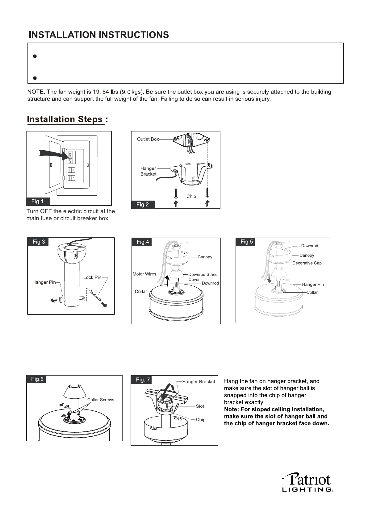
Remove the lock pin and take
off the hanger pin.
Decorative
Cap
Thread the motor wires through
the downrod stand cover,
decorative cap (Making sure the
smooth side of decorative cap is
facing downward.), canopy and
downrod.
Loosen the collar screws out part way.
Insert the downrod into the collar.
Slide hanger pin through holes of
collar and downrod.
Tighten the two collar screws.
Slide lock pin into hanger
pin until it is locked into position.
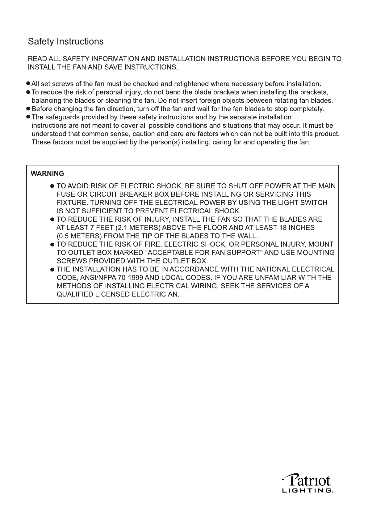
IMPORTANT:
BEFORE YOU BEGIN INSTALLATION, CAREFULLY READ ALL INFORMATION PROVIDED IN THE SAFETY
INSTRUCTIONS AND INSTALLATION INSTRUCTIONS. IF IN DOUBT, CONSULT A QUALIFIED
ELECTRICIAN.
SAVE ALL INSTRUCTIONS.
Tighten the hanger bracket to the outlet box
with two mounting screws. (To reduce the
risk of fire, electric shock, or personal injury,
mount to an outlet box marked "Acceptable
for fan support" and use mounting screws
provided with the outlet box.)
Note: For sloped ceiling installation, make
sure that the chip of the hanger bracket
is toward the floor.
Downrod Stand
Cover
220104
SUR
ON
Code example:
1-ON 2-OFF 3-ON 4-OFF on both SUR
Switches.
Note: If you have two ceiling fans with
2 remote control units, set 2 different
codes for each set of transmitter / receiver.
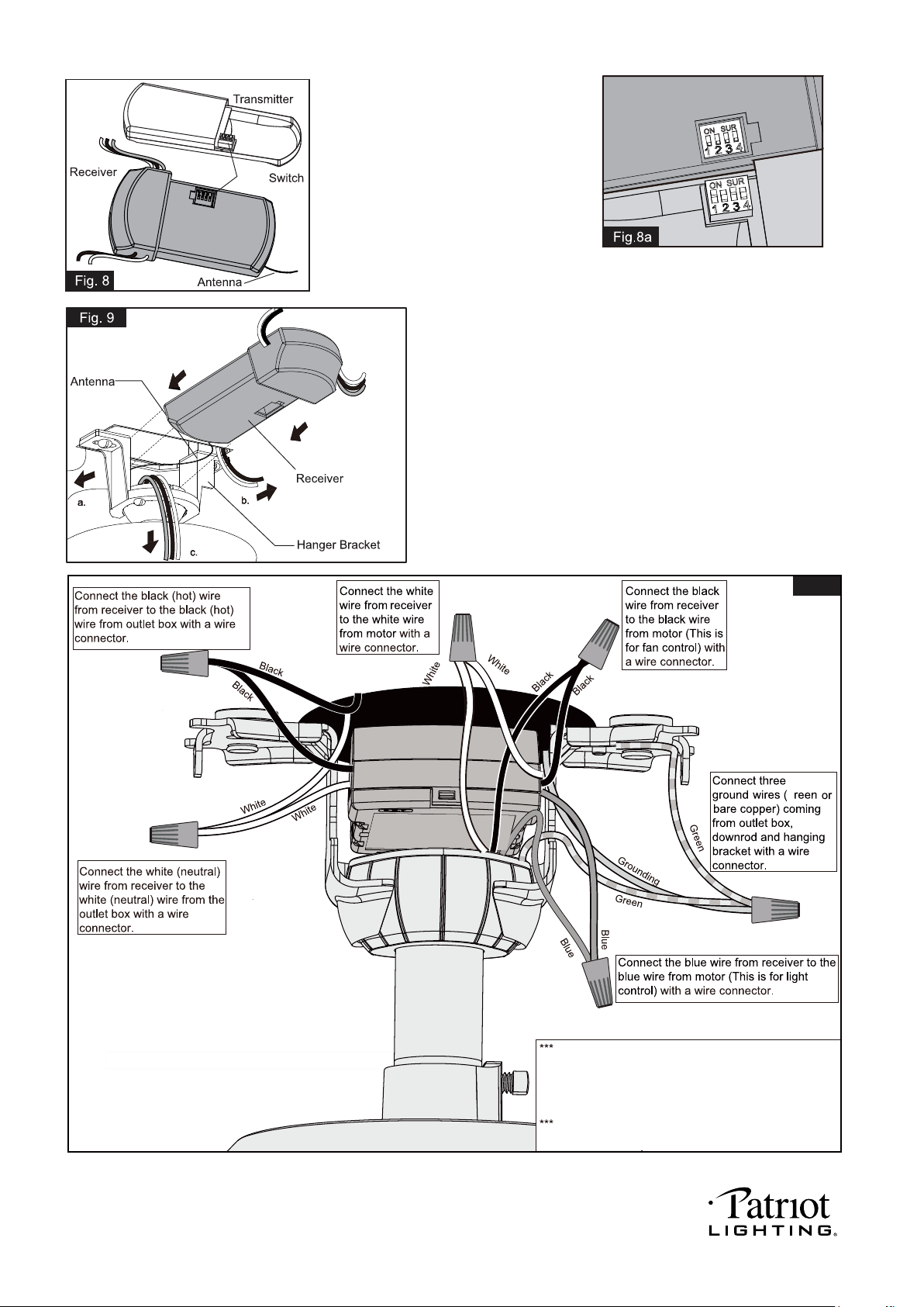
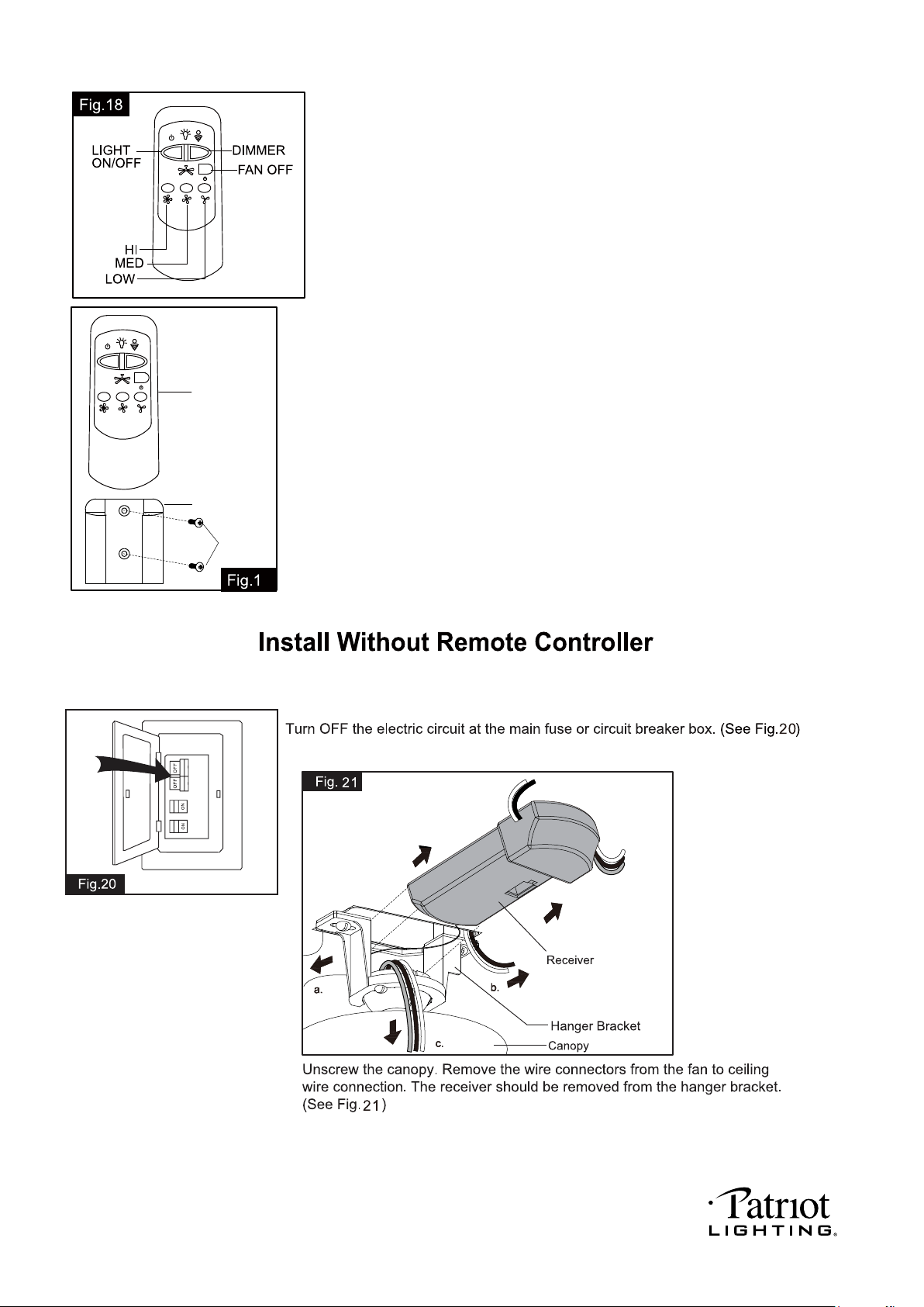
Move ground wires (a), outlet box wires (b), and motor
wires (c) away from the center of the hanger bracket.
Then slide receiver through hanger bracket as shown.
Antenna end first, until it is centered. Finally, cut motor
wires (c) to length needed for connections.
G
Fig.10
Both the transmitter and receiver have a 4-key
unit code on each SUR Switch (Fig.8) and by
default, all keys are pre-set to the “off” position.
This means that the transmitter and receiver are
already paired together. However, if you have
SUR
multiple fans and remote controls and want to
avoid interference between them, you can “pair”
other transmitters and receivers together by
adjusting the SUR switches, so the same
numbered keys are in the “ON” position
on both (Fig.8a).
Note: The ceiling fan may work abnormally
if there is interference from other remote
controls.
PAGE: 6 / 11
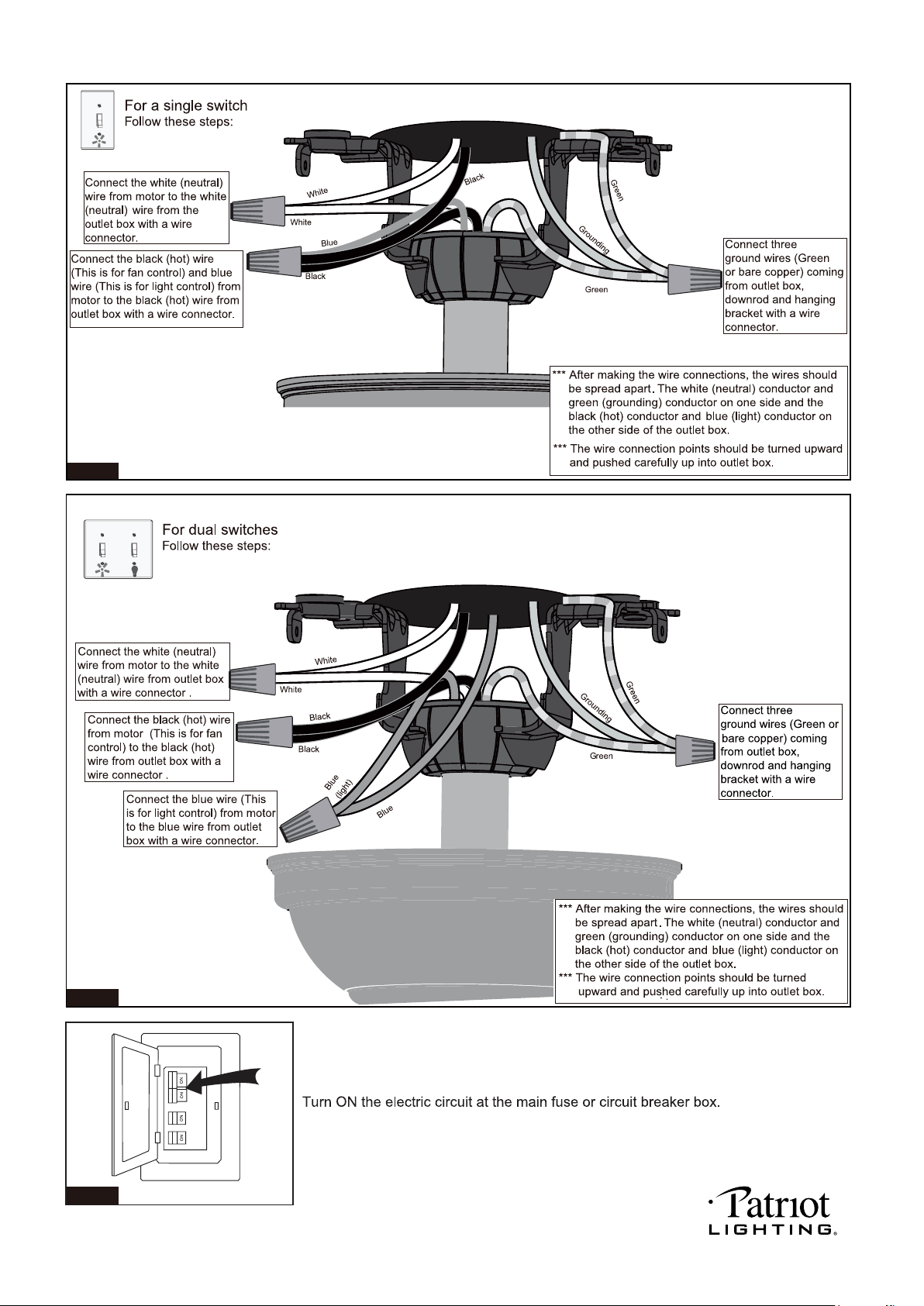
After making the wire connections, the wires should be
spread apart. The white (neutral) conductor from receiver
and outlet box with green (grounding) conductor on one
side; the black (hot) conductor from receiver and outlet box
with the white, black and blue conductor from receiver and
motor on the other side of the outlet box.
The wire connection points should be turned upward and
pushed carefully up into outlet box.
ON SUR
220104
PAGE: 7 / 11
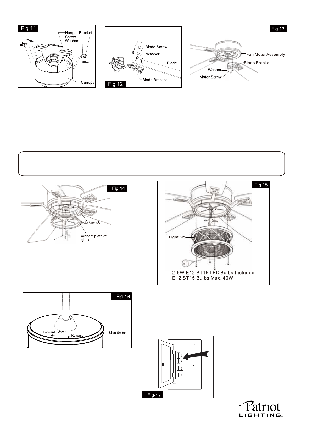
There are four hanger bracket screws and lock
washers. Remove two screws and lock washers
from the hanger bracket (one from each side)
and loosen the other two remaining screws.
Align the “L shaped” slots of the canopy with the
two remaining screws on the hanger bracket and
push the canopy upwards to engage the slots and
turn clockwise to lock in place. Tighten the screws
and install the other two hanger bracket screws and
lock washers into the remaining holes of the canopy
and tighten.
Tighten blades to blade brackets by
using blade screws and washers.
Turn ON the electric circuit at the main
fuse or circuit breaker box.
The slide switch on motor assembly sets direction of fan rotation.
Select the desired direction of fan rotation. Push the slide switch
left for "Forward" and right for "Reverse".
Note: Wait for fan to stop before reversing the direction of
blade rotation.
Thread the motor assembly wires through connect plate
of light kit. Remove one fix screw from bottom of fan motor
assembly (for later use), and loosen the other two fix screws.
Secure the connect plate of light kit to fan motor assembly with
previous fix screw the rotate the connect plate of light kit until it
locks into position, tighten the other two fix screws.
Connect the blue wire from motor to the black wire from light kit
by wire connectors. And connect the white wire from motor to
the white wire from light kit by wire connectors.
Remove four fix screws from connect plate of light kit (for later use),
secure the light kit to connect plate of light kit with previous for fix
screws and tighten them.
Install LED bulbs (included). See relamping label at socket area
or packaging for maximum wattage.
Rotate the motor to remove the motor screws and washers
from fan motor assembly. Secure blade brackets to the motor
with washers and motor screws.
Note: Before installing blade brackets to the motor, please
remove the plastic inserts.
Install fan light
WARNING:
This fan light has a built-in current limiting device in the receiver of remote control to conserve energy. The fan light will shut off shortly if the combined
wattage of the installed bulbs exceeds 190Watts. Please replace light bulbs with lower wattage bulbs which show on relamping label or package and
then turn on the fan light again.
Fix Screw
220104
PAGE: 8 / 11
Transmitter
Wall Bracket
Screw
9
Note: Remote controller can not be used along with a solid-state speed control at the same time.
Install the battery (9V, included) into the transmitter.
* Press "HI" button to turn on the fan at high speed.
* Press "MED" button to turn the fan in medium speed.
* Press "LOW" button to turn the fan in low speed.
* Press "FAN OFF" button to turn off the fan.
* Press "LIGHT ON/OFF" button to turn on or turn off the light.
* Press and hold the "DIMMER" button to dim or brighten lights to the desired level and
release, and the brightness level will be memorized. Turn on the light again, then fan light will
be restored to the brightness-level at which it was dimmed last time.
Note:
1. This remote controller has a memory function setting. The fan will operate at the same
speed and the fan light will stay at the same brightness-level as the last time the power
supply was turned off.
2. Compatible Wall Switches: Menards SKU# 363-2615 / 363-5815.
3. Compatible with E12 (C) base dimmable LED bulb: Menards SKU# 353-8305.
Install the transmitter wall bracket on the wall with two screws
and place transmitter in it carefully.
220104
PAGE: 9 / 11
Fig.22
Fig.23
Fig.24
220104
PAGE: 10 / 11
220104
PAGE: 11 / 11
220104
