Loading ...
Loading ...
Loading ...
10
English
Electrical Connection for USA Installations
WARNING
ELECTRICAL SHOCK HAZARD
● Ensure the wires are connected to the proper terminal
block.
● Failure to follow these instructions can result in
electrical shock, severe personal injury or death.
4-Wire Conduit Installation (Recommended)
● Refer to Fig. 6 for 4-wire connection guidance.
3-Wire Power Cord
or Conduit
Installation
● Refer to Fig. 7 for 3-wire connection guidance.
Wall Receptacle for Power Cord
4 Wire receptacle (NEMA 14-50R)
3 Wire receptacle (NEMA 10-50R)
4-Wire Power Cord Installation (Recommended)
1. Remove the terminal box cover on the back of the range
by removing the 1 screw using a Phillips screwdriver. Keep
the screw for later use.
2. Loosen the 2 screws of strain relief bracket using a Phillips
screwdriver.
3. Strip off ⅝” (15mm) of the insulation layer from the end of
the four power cords.
4. Insert the 4-Wire power cord through the strain relief
bracket and tighten. Allow enough slack to easily attach
the power cord terminals to the terminal blocks.
5. Loosen the terminal block screws and insert the power
wires into the proper terminal as following instruction:
− L1 is the Black Power wire. Attach to the L1 terminal.
− L2 is the Red Power wire. Attach to the L2 terminal.
− Neutral is the White power wire. Attach to the middle
(N) terminal.
− Ground is the Green power wire. Attach to the screw
post (See Fig 6).
6. Tighten all of the terminal block screws (maximum torque
is 6 N m).
7. Replace the terminal box cover and tighten with the 1
screw.
8. Refer to Fig. 6 for 4-Wire connection guidance.
L1
L2
N
Fig. 6
Ground Wire
(Green, 8AWG)
Power Wire
(L1: Black, 8AWG)
Neutral Wire
(White, 8AWG)
Power Wire
(L2: Red, 8AWG)
Strain Relief Bracket
Screw Post
Terminal Blocks
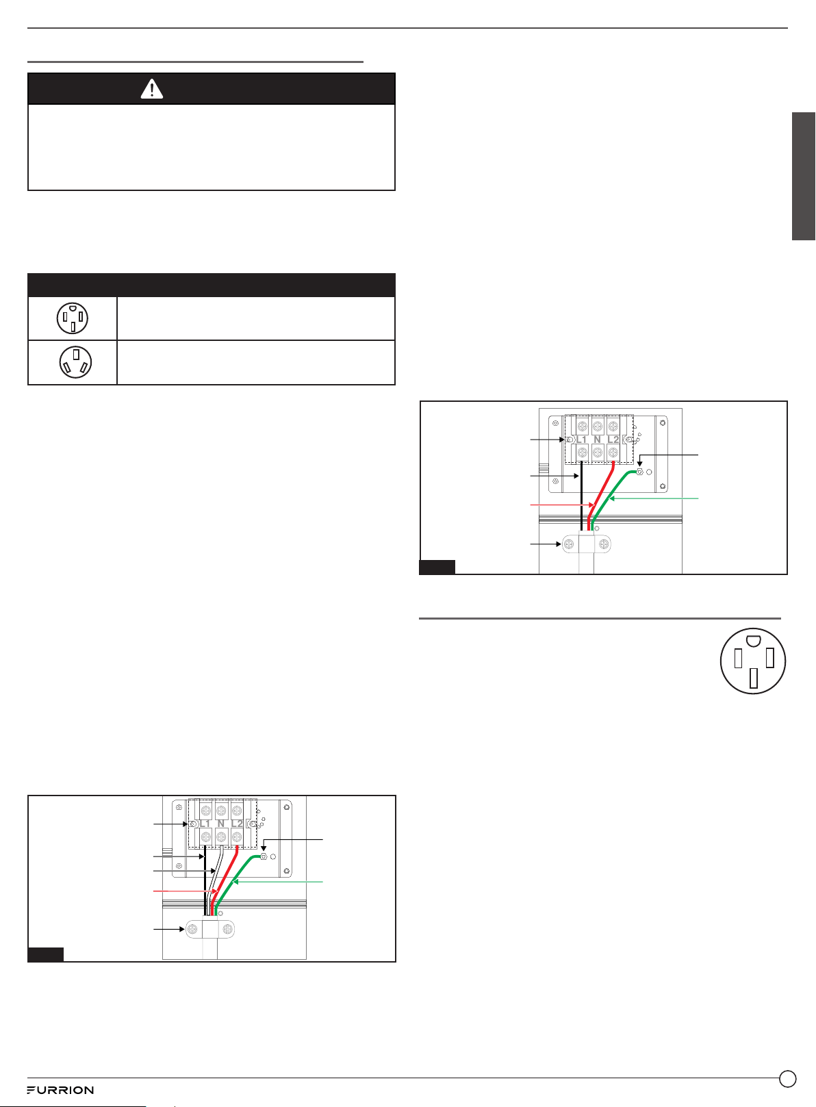
3-Wire Power Cord Installation
1. Remove the terminal box cover on the back of the range
by removing the 1 screw using a Phillips screwdriver. Keep
the screws for later use.
2. Loosen the 2 screws of strain relief bracket using a Phillips
screwdriver.
3. Strip off ⅝”(15mm) of the insulation layer from the end of
the three power cords.
4. Insert the 3-Wire power cord through the strain relief
bracket and tighten. Allow enough slack to easily attach
the power wire terminals to the terminal blocks.
5. Loosen the terminal block screws and insert the power
wires into the proper terminal as following instruction:
− L1 is the Black Power wire. Attach to the L1 terminal.
− L2 is the Red Power wire. Attach to the L2 terminal.
− Ground is the Green power wire. Attach to the screw
post (See Fig 7).
6. Tighten all of the terminal block screws (maximum torque
is 6 N m).
7. Replace the terminal box cover and tighten with the 1
screw.
8. Refer to Fig. 7 for 3-Wire connection guidance.
L1
L2
N
Ground Wire
(Green, 8AWG)
Power Wire
(L1: Black, 8AWG)
Power Wire
(L2: Red, 8AWG)
Strain Relief Bracket
Screw Post
Terminal Blocks
Fig. 7
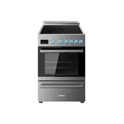
Electrical Connection for Canada Installations
1. The electrical connection must be carried
out in accordance with local codes and
regulations.
2. Plug the power cord from the range into a
dedicated 50 amp 4-prong polarized grounded
type outlet.
Loading ...
Loading ...
Loading ...