Loading ...
Loading ...
Loading ...
SERVICE AND ADJUSTMENTS
,,,Ul,, ,,,,,H,,,,HH,, U ,H, "H ,"'H' ',"""11 ,,,,H,HmH ,, , J
TO REPLACE MOTION DRIVE BELT TO ADJUST STEERING WHEEL ALIGNMENT
(See Fig. 30)
Park the tractor on level surface Engage parking brake+
Forease of service there is abelt installation guide decal on
bottom of left footrest It is not necessary to remove mower+
BELT REMOVAL -
• Engage parking brake (creates slack in belt).
• Remove mower drive belt from electric clutch pulley
only (See "TO REPLACE MOWER DRIVE BELT" in
this section of this manual),.
• Roll motion drive belt off transaxle pulley.
• Roll belt off clutching idler pulleys, then off engine
pulley and front V-idler pulley.
• Pull belt out of al! belt keepers.
BELT INSTALLATION -
° Place V part of belt into grooves on engine pulley and
front V-idtet, making sure to route belt inside ..ofbelt
. keepe.._s..
• ut beltcoming.from V-i_iler aboye midspar_belt keeRei:;
then" onto clutching idler pu.lleys :as shown "
, Make sure V part of belt engages V-idler.
- Place belt around transaxle pulley, beginning at top.
V part of belt should engage transaxle pulley.
° Place long lower section of belt through loop in midspan
belt keeper.
, Check to be +sure be!t is on proper side _)f all belt
keepers
• Reinstall mower drive .beltonto electric clutch pulley.
IMPORTANT: +CHtECKBRAKE AbJUSTMENT.
VIEWED FROM L.H. SIDE OF TRACTOR
CLUTC:HING
IDLER
BELT
CLUTCHING tKEEPER
FLAT IDLER
BELT
KEEPER P_LLEY'
AS VIEWED. FFiOM BOTTOM _..
FIG. 30
If steering wheel crossbars are not horizontal (left to right)
when wheels are positioned straight forward, remove steer-
ing wheel and reassemble per'instructions in the Assembly
section of this manual.
FRONT WHEEL TOE-IN ADJUSTMENT
Front wheel toe-in isrequired for'proper'steering operation+
Toe-in was set at the factory and adjustment should not be
necessary. If parts in the front axle or steering mechanism
have been replaced or damaged, check toe-in and adjust
if necessary.
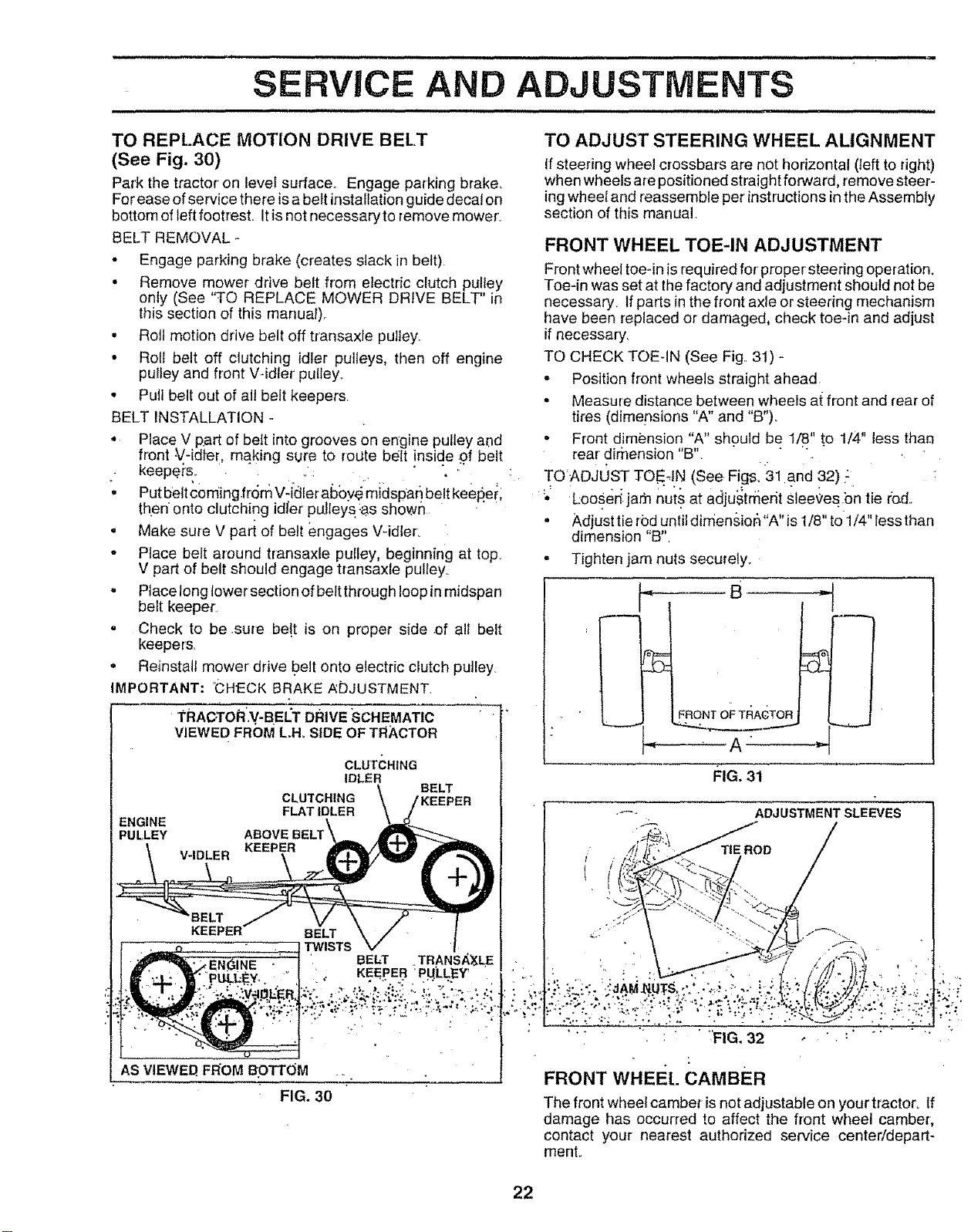
TO CHECK TOEqN (See Fig.. 3t) -
- Position front wheels straight ahead
• Measure distance between wheels at front and rear of
tires (dimepsions "A" and "B")..
, Front dimension "A" sh.ould be 1/8" to 1/4" less than
rear dirhension "B". " ,
TO ADJL)ST TOE4N (See. Figs° 31 and 32) ,:
:•' L:ooser_.jam nui'+sat adju_,trfierit slee_'es bn tie fed..
, Adjust tie rod until dimensior_"A" is t/8" to 1/4" less than
dimension "B".
- Tighten jam nuts secutety+
FRONT OF TFIACTOR
FIG+31
ADJUSTMENT SLEEVES
FRONT WHEEt. CAMBER
The front wheel camber isnot adjustable on your tractor+ If
damage has occurred to affect the front wheel camber,
contact your nearest authorized service center/depart-
menL
22
Loading ...
Loading ...
Loading ...