Loading ...
Loading ...
Loading ...
j iiii lU i JlllUl,U i ii ii nl ,1111,111111u ilU ii . ,UlllUl
SERVICE AN ADJUSTMENTS
Jl ,,m U l i i i
TO REPLACE MOWER DRIVE BELT
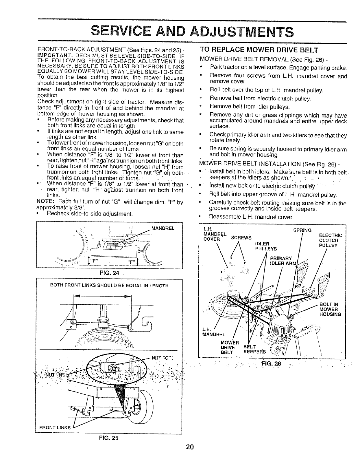
FRONT-TO-BACK ADJUSTMENT (See Figs. 24 and 25) -
IMPORTANT: DECK MUST BE LEVELSIDE-TO-SIDE tF
THE FOLLOWING FRONT-TO-BACK ADJUSTMENT IS
NECESSARY, BE SURE TO ADJUST BOTH FRONT LINKS
EQUALLY SO MOWER WILL STAY LEVEL SIDE-TO-SIDE
TO obtain the best cutting results, the mower housing
should be adjusted so the front is approximately 1/8" to 1/2"
lower' than the rear when the mower is in its highest
position
Check adjustment on right side of tractor Measule dis-
tance "F" directly in front of and behind the mandrel at
bottom edge of mower' housing as shown,
• Before making any necessary adjustments, check that
both front links are equal in length
• If links are not equal in length, adjust one link to same
length as other link,
- To lower fl'ont of mower housing, loosen nut"G" on both
front [inks an equal number of turns,
° When distance "F" is 1/8" to t/2" lower at front than
rear, tighten nut"H" against trunnion on both front links,
• To raise float of mower housing loosen nut' H_'from
ttunnior_ on both fr.oht link&..Tighten nut"'G_' 0h. both,
front finks an.equal'number of turns. :
. When distance "F" js 178" to 1/2" 16wer'at'fz:on:t than
rear, tighten nut "H" against trunnion on both front
links.
NOTE: Each full turn of hut "G" will (}hange dim. "F; by
approximately 3/8",
o Recheck side-to-side adjustment
-. • ' ,:i MANDREL
FIG, 24
BOTHFRONTLtNKSSHOULO BEEQUALINLENGTH
FRONTLtNKS
FIG. 25
2O
MOWER DRIVE BELT REMOVAL (See Fig. 26) -
• Park tractor on a level surface.. Engage parking brake.
• Remove four screws from LH mandrel cover and
remove covet.
• Roll belt over the top of L H mandrel pulley.
,, Remove belt from electric clutch pulley
o Remove belt from idler pulleys.
. Remove any dirt or grass clippings which may have
accumulated around mandrels and entire upper deck
surface.
• Check primary idler arm and two idlers to see that they
rotate freely
• Be sure spring is securely hooked to primary idler arm
and bolt in mower housing
MOWER DRIVE BELT INSTALLATION (See Fig 26)-
• Install bel.t in both idlers. Makesure belt is in both belt
keepers afthe idlers as shown,_" : . : .; "
. install new belt onto elec![icrclu}ch ;utle}/ '
" R01lbblt.into upper groove of L,H,_mandrel puliey,
• Carefully check belt routing rh,_king sure belt is in the
grooves correctly and inside belt keepers.
• Reassemble LH mandrel cover.
L,N.
MANDREL
CO';'ER" SCREWS
SPRING
IDLER
PULLEYS
PRIMARY
I
ELECTRIC
CLUTCH
PULLEY
BOLT IN
MOWER
HOUSING
MANDREL \
MOWER
DRIVE BELT \
BELT KEEPERS !
: t= G
Loading ...
Loading ...
Loading ...