Loading ...
Loading ...
Loading ...
SERVICE AI ADJUSTMENTS
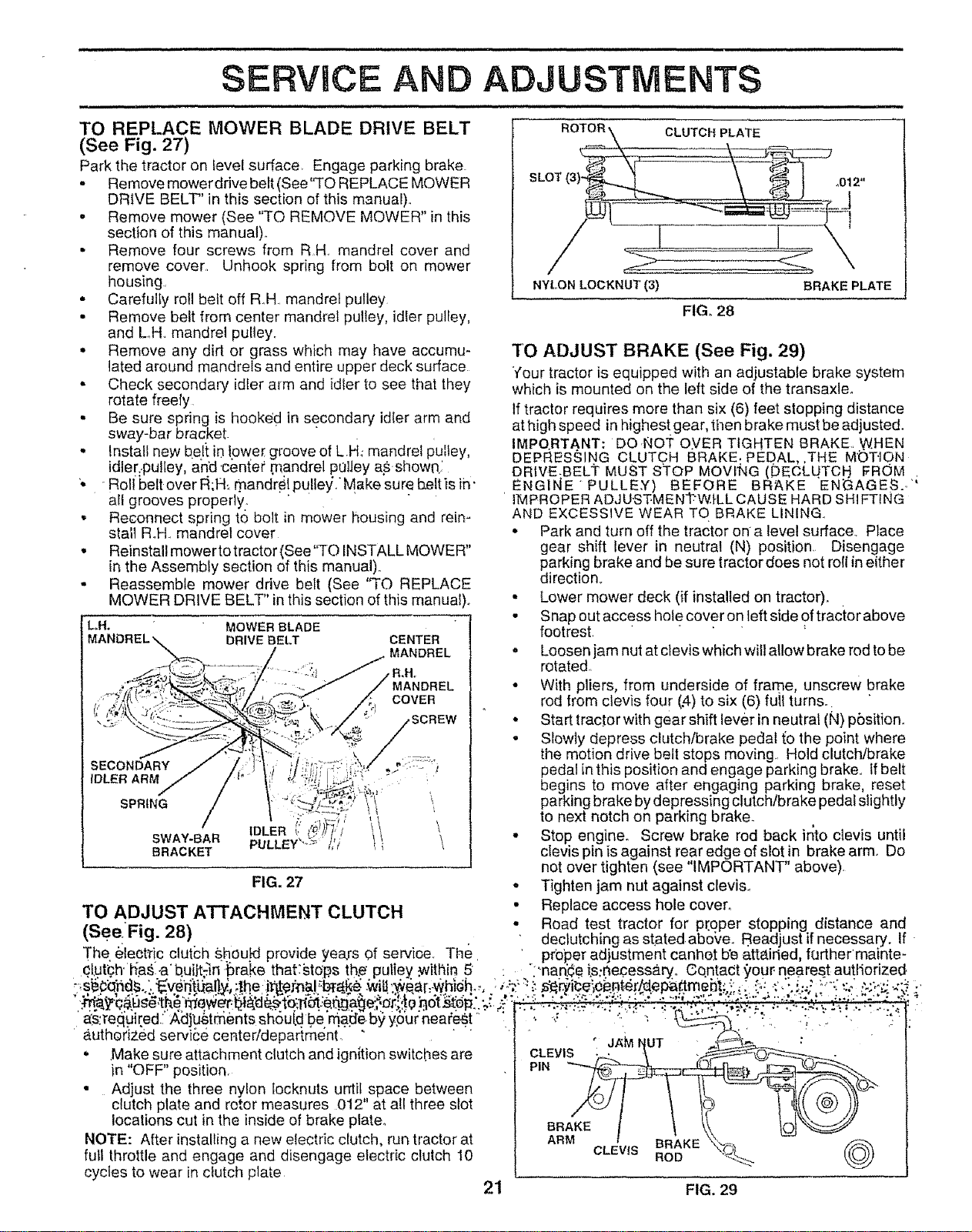
TO REPLACE MOWER BLADE DRIVE BELT
(See Fig. 27)
Park the tractor on level surface Engage parking brake
• Remove mower drive belt (See'TO REPLACE MOWER
DRIVE BELT" in this section of this manual)..
• Remove mower (See "TO REMOVE MOWER" in this
section of this manual)_
• Remove four screws from RH. mandref cover and
remove cover. Unhook spring from bolt on mower
housing.
• Carefully roll belt off RH.. mandrel pulley
• Remove belt from center mandrel pulley, idier pulley,
and LH. mandrel pulley.
• Remove any dirt or grass which may have accumu-
lated around mandrels and entire upper deck surface
• Check secondary idler alm and idler to see that they
rotate freely
• Be sure spring is hooke d in secondary idler arm and
sway-bar bracket.
. Install new belt io Ipwe[ groove of LH_.mandrel pulley,
idler;.pultey, and _center mandrel pelley asshow01
'- Roll belt over t_;FI_.mandre! PUlle_j."Make sure be!t _sih"
all grooves properly.
• Reconnect spring to bolt in mower housing and rein-
stall R,.H.mandrel cover
• Reinstall mower to tractor (See"TO INSTALL MOWER"
in the Assembly section of this manual)..
• Reassemble mower drive belt (See ''TO REPLACE
MOWER DRIVE BELT" in this section of this manual).
L,H. MOWER BLADE
DRIVE BELT
CENTER
MANDREL
MANDREL
COVER
SECONDARY
IDLER ARM
SPRING
SWAY-BAR
BRACKET
\
FIG. 27
TO ADJUST ATTACHMENT CLUTCH
CLUTCH PLATE
NYLON LOGKNUT (3)
FIG. 28
BRAKE PLATE
TO ADJUST BRAKE (See Fig. 29)
Your tractor is equipped with an adjustable brake system
which is mounted on the left side of the transaxle°
If tractor requires more than six (6) feet stopping distance
at high speed in highest gear, tt_en brake must be adjusted.
IMPO.RTANT: DO.NO'i _O.VER TIGHTEN BRAKE.. W.HEN
DEPRESSING CLUTCH BRAKE. PEDAL,,THE MOTION
DRIVE.BELi" MUST STOP MOVrNG (DECLU.TCH FROM .
ENGINE'PULLE.Y) BE.FORE BRAKE EN_AGES..."
' IMPROPER ADJU'S'f:MENTW.I-LL CAUSE HARD SHI FTING
AND EXCESSIVE WEAR TO BRAKE LINING.
• Park and turn off the tractor on a level surface. Place
gear shift lever in neutral IN) position Disengage
parking brake and be sure tractor does not roll in either
direction°
• Lower mower deck (if installed on tractor)..
• Snap out access hote cover on left side of tractor above
footrest.
= Loosen jam nut at clevis which will allow brake rod to be
rotated.
• With pliers, from underside of frame, unscrew brake
rod trom clevis four (.4)to six (6) full turns.r
° Start tractor with gear shift lever in neutral IN) pbsitien.
• Slowly depress clutch/brake pedal to the point where
the motion drive belt stops moving. Hold clutch/brake
pedal in this position and engage parking brake° If belt
begins to move after engaging parking brake, reset
parking brake by depressing clutch/brake pedal slightly
to next notch on parking brake_
• Stop engine. Screw brake rod back into clevis until
clevis pin is against rear edge of slot in brake arm. Do
not over tighten (see IMPORTANT" above).
• Tighten jam nut against clevis..
• Replace access hole cover.
(SeeFi,', 28\ • Road test tractor for proper stopping distance and
• : _" / . ' declutching as stated abo_e. Readjust if necessary. If
The eleet_ric clutch shou+tdprovide yea.rs of service. The ' proper adjustment canho.t b'ea.tta.iried, further'mainte-
qt.ut'ch.'h_as.a b.uiit-m _rake that:sto'ps th.e'putiey .within 5 : "i'nan'.¢ets:neoessaryo Gqntadt _our nearest auttiorized.
'.:trY_2"c.aus'g,'therdewer;t_._._o-It_:eqga£1e_,,o_;,_0_ot_ep _,:_':..-_:. _.,- ,--:, _.._,:.. ._,--*--.:_,,;:. ;"-. -." =:;':". : - ',.
"a•_:'re_p,[ed 7"A_J_4_tbr;,_ntsst_'ouf.'d,be'm.a_e 5_ y,our'nearest _:' ! i ' :. _:'" "' "." '_: : °_"" *'.;:." " .'_":i.":." ":.:'_
_.uthorized serviEe center/department. " " " _ . ._. ...... \_... .
. ,Make sure attachment clutch and ignition switches are CLEVIS _,,.,..,_u. .__.
in"O "position P,.
• Adjust the three nylon tocknuts until space between _-, / I \ IL -- '_//_'_>_"
clutch plate and rotor measures 012" at all three slot _'_'_J I \ I_ I _[1 _ )))
locations cut in the inside of brake plate° BR_KE / ,-,>^ \\ tOt_
NOTE: After installing a new electric clutch, run tractor at ARM BRAKE _¢-_,_ --
CLEVIS "_ \O_. (((
full throttle and engage and disengage electric clutch 10 ROD "_-_% (O@_
cycles to wear in clutch plate
21 FIG. 29
Loading ...
Loading ...
Loading ...