
Loading ...
Loading ...
Loading ...
9
mWARNING! This charger does not automatically
turn o when the battery is fully charged. Please take care
not to leave the battery plugged into the charger. Switch
o or unplug the charger at the mains when charging is
complete.
5. Timely recharging of the battery will help prolong the
battery's life. You must recharge the battery pack when
you notice a drop in the equipment's power.
IMPORTANT! Never allow the battery pack to become fully
discharged as this will cause irreversible damage to the
battery.
6. When charging is complete, remove the battery from the
charger by pulling the push lock button and sliding the
battery backward to unlock it from the charger.
Assembly
The product must be fully assembled before operation. Do not
use the device when only partially assembled or assembled
with damaged parts. Follow these instructions to assemble the
metal detector.
Pole Assembly
1. Insert the lower pole into either end of the middle pole
until the locking button clicks into one of the holes.
(Fig. 4).
2. Insert the upper pole into the other end of the middle pole
until the locking button clicks in one of the holes.
3. Adjust the length by pressing the locking buttons and
moving them into dierent holes along the shaft of the
middle pole. Tighten both locking collars once you have
set the desired pole length (Fig. 5).
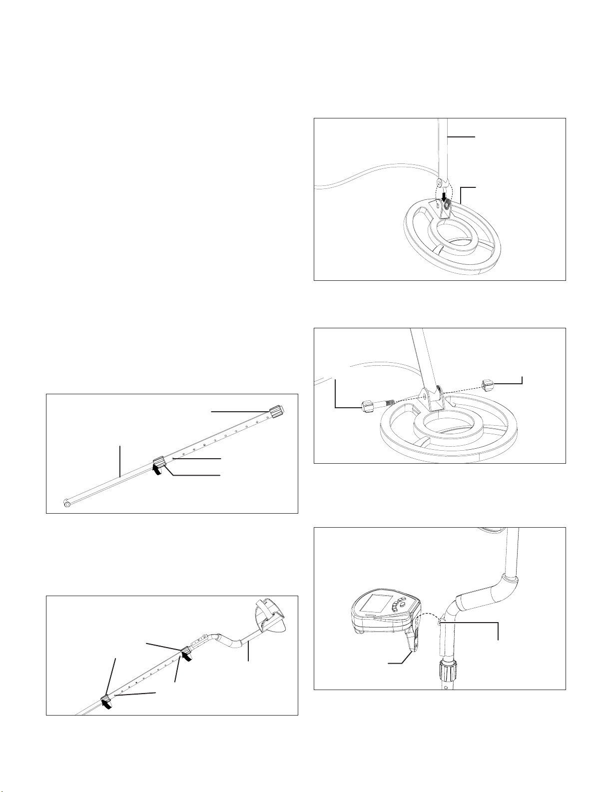
Search Coil Assembly
1. Fit the end of the lower pole between the 2 tabs of the
search coil and align the holes (Fig. 6).
2. Secure them together with the search coil bolt and knob.
Then tilt the search coil to your desired angle and tighten
the search coil knob and bolt to secure it in place (Fig. 7).
Control Panel Assembly
3. Fit the control panel by hooking it on the small hook on
the back of the control panel plate (Fig. 8).
Fig. 4
Middle pole
Lower pole
Locking button
Locking collar
Fig. 5
Locking
buttons
Locking
collars
Upper pole
Fig. 6
Lower pole
Search coilAlign the holes
Fig. 7
Search coil knob
Search coil bolt
Fig. 8
Hook
Control panel
Loading ...
Loading ...
Loading ...