
OVER THE RANGE MICROWAVE
Installation Guide
and Users Manual

WARNING: This product can expose you to chemicals including nickel, which is known to the
State of California to cause cancer. For more information, go to www.P65Warnings.ca.gov.
ZLINE Kitchen and Bath provides Attainable Luxury, where the kitchen and bath of
your dreams is never out of reach. Through our unique designs and unparalleled
quality, we’re dedicated to providing you an elevated experience in the heart of your
home. With an endless selection of features and finishes, our inspiration is your reality.
ZLINE is fueled by a passion for innovation; A relentless pursuit of bringing the highest
end luxury designs and professional features into everyone’s homes. Because we
continually strive to improve our products, we may change specifications and designs
without prior notice.

Warranty
COVERAGE
ZLINE Kitchen and Bath microwave parts will be warrantied for two years from the
original purchase date for the original purchaser of the product.
TERMS
This warranty applies only to the original purchaser of the product installed for
normal residential use. This is defined as a single-family, residential dwelling in a
non-commercial setting. Commercial settings include but are not limited to: schools,
churches, hotels, restaurants, vacation rentals such as Airbnb, day care centers,
private clubs, fire stations, common areas in multi-family dwellings, nursing homes,
food service locations, and institutional food service locations such as hospitals or
correction facilities. This warranty is non-transferable and will not be extended based
on the date of installation. The warranty applies only to products installed in the
continental United States and the District of Columbia. Warranty shall not apply and
ZLINE Kitchen and Bath is not responsible for damage resulting from negligence,
improper maintenance, misuse, abuse, alteration of or tampering with the appliance,
accident, natural disaster, improper electric supply, unauthorized service or repair,
improper installation, or installation not in accordance with the instructions contained
in the manual or the local codes.
WHAT IS NOT COVERED
1. Installation or start-up damages or problems caused by improper installation or
use.
2. Damage related to unauthorized service or unauthorized parts.
3. Installation in any commercial or non-residential application.
4. Aesthetic damage, scratches, or natural wear caused by normal use.
5. Second-hand, open box products, or products purchased from an unauthorized
retailer.
TABLE OF CONTENTS
IMPORTANT SAFETY INSTRUCTIONS 1
ELECTRICAL REQUIREMENTS 3
PARTS AND TOOLS 5
INSTALLATION 7
RADIO INTERFERENCE 26
UTENSIL TEST 26
DIFFERENT MATERIALS IN THE MICROWAVE 27
SETTING UP YOUR OVEN 28
OPERATION 29
TROUBLESHOOTING 44

21
General Safety
General Safety
SAFETY INSTRUCTIONS
• Do not attempt to operate this oven with the door open since open-door
operation can result in harmful exposure to microwave energy. It is important not
to defeat or tamper with the safety interlocks.
• Do not place any object between the oven front face and the door or allow soil
or cleaner residue to accumulate on sealing surfaces.
• Do not operate the oven if it is damaged. It is particularly important that the oven
door closes properly and that there is no damage to the:
• Door (bent or not closing)
• Hinges and Latches (broken or loosened)
• Door seals and sealing surfaces (wear and tear)
• When using electrical appliances basic safety precautions should be followed,
including the following:
• To reduce the risk of burns, electric shock, fire, personal injury, or exposure to
excessive microwave energy, read all instructions before using the appliance.
• This appliance must be grounded or connected to a properly grounded
outlet. Install this appliance only in accordance with the provided installation
instructions.
• Some products such as whole eggs and sealed containers (i.e. closed glass jars)
should not be heated in this oven.
• Use this appliance only for its intended use as described in the manual. Do
not use corrosive chemicals or vapors in this appliance. This type of oven is
specifically designed to heat, cook, or dry food.
• Close supervision is necessary when used by children.
• Do not operate this appliance if it has a damaged cord or plug, if it is not
working properly, or if the entire unit has been damaged.
• This appliance should be serviced only by qualified service personnel.
• Do not cover or block any openings on the appliance.
• Do not store this appliance outdoors. Do not use this product near water - for
example, near a kitchen sink, in a wet basement, near a swimming pool, or
similar locations.
• Do not immerse cord or plug in water.
• Keep cord away from heated surface.
WARNING
SAFETY INSTRUCTIONS
• Do not let cord hang over edge of table or counter.
• When cleaning surfaces of door and oven that comes together on closing the
door, use only mild, nonabrasive soaps, or detergents applied with a sponge or
soft cloth.
• To reduce the risk of fire in the oven cavity:
• Do not overcook food. Carefully attend appliance when paper,
plastic, or other combustible materials are placed inside the oven to
facilitate cooking.
• Remove wire twist-ties from paper or plastic bag before placing bag in
oven. If material inside of the oven ignite, keep oven door closed, turn
oven off, and disconnect the power cord, or shut off power at the fuse
or circuit breaker panel.
• Do not use the cavity for storage purposes. Do not leave paper
products, cooking utensils, or food in the cavity when not in use.
• Liquids and other foods must not be heated in sealed containers since they are
liable to explode.
• To reduce the risk of injury to persons
• Do not overheat the liquid.
• Stir the liquid both before and halfway through heating it.
• Do not use straight-sided containers with narrow necks.
• After heating, allow the container to stand in the microwave oven for a
short time before removing the container.
• Use extreme care when inserting a spoon or other utensil into the
container.
• Do not operate any heating or cooking appliance beneath, over, or near the
appliance. It is okay to use the microwave above another heating appliance.
• Suitable for use above both gas and electric cooking equipment.
• Do not mount over sink.
• Do not store anything directly on top of the appliance surface when the
appliance is in operation.
• Clean ventilation hoods frequently - Grease should not be allowed to
accumulate on hood or filter.
• Use care when cleaning the vent-hood filter. Corrosive cleaning agents may
damage the filter.
43
Electrical Connection
Electrical Connection
BEFORE INSTALLATION
ELECTRIC SHOCK HAZARD
• Improper use of the grounding can result in a risk of electric shock.
• 60Hz, 120V, 15A
• Consult a qualified electrician if the grounding instructions are not completely
understood or if doubt exists as to whether the appliance is properly grounded.
If it is necessary to use an extension cord, use only a 3-wire extension cord that
has a 3-blade grounded plug and 3-slot receptacle that will accept the plug
on the appliance. The marked rating of the extension cord shall be equal to or
greater than the electrical rating of the appliance.
• A short power supply cord is provided to reduce the risks resulting from
becoming entangled in or tripping over a longer cord. Longer cord sets or
extension cords are available and may be used if care is exercised in their use.
If a long cord or extension cord is used:
• The marked electrical rating of the cord set or extension cord should be
at least as great as the electrical rating of the appliance.
• The extension cord must be a grounding-type 3-wire cord.
• The longer cord should be arranged so that it will not drape over the
counter top or tabletop where it can be pulled on by children or
tripped over unintentionally.
• Touching some of the internal components can cause serious personal injury or
death. Do not disassemble this appliance.
• Do not plug this unit into an outlet until it is properly installed and grounded
This product requires a three-prong grounded outlet. The installer must perform
a ground continuity check on the power outlet box before beginning the
installation to ensure that the outlet box is properly grounded. If not properly
grounded, or if the outlet box does not meet electrical requirements noted, a
qualified electrician should be employed to correct any deficiencies.
WARNING
BEFORE INSTALLATION
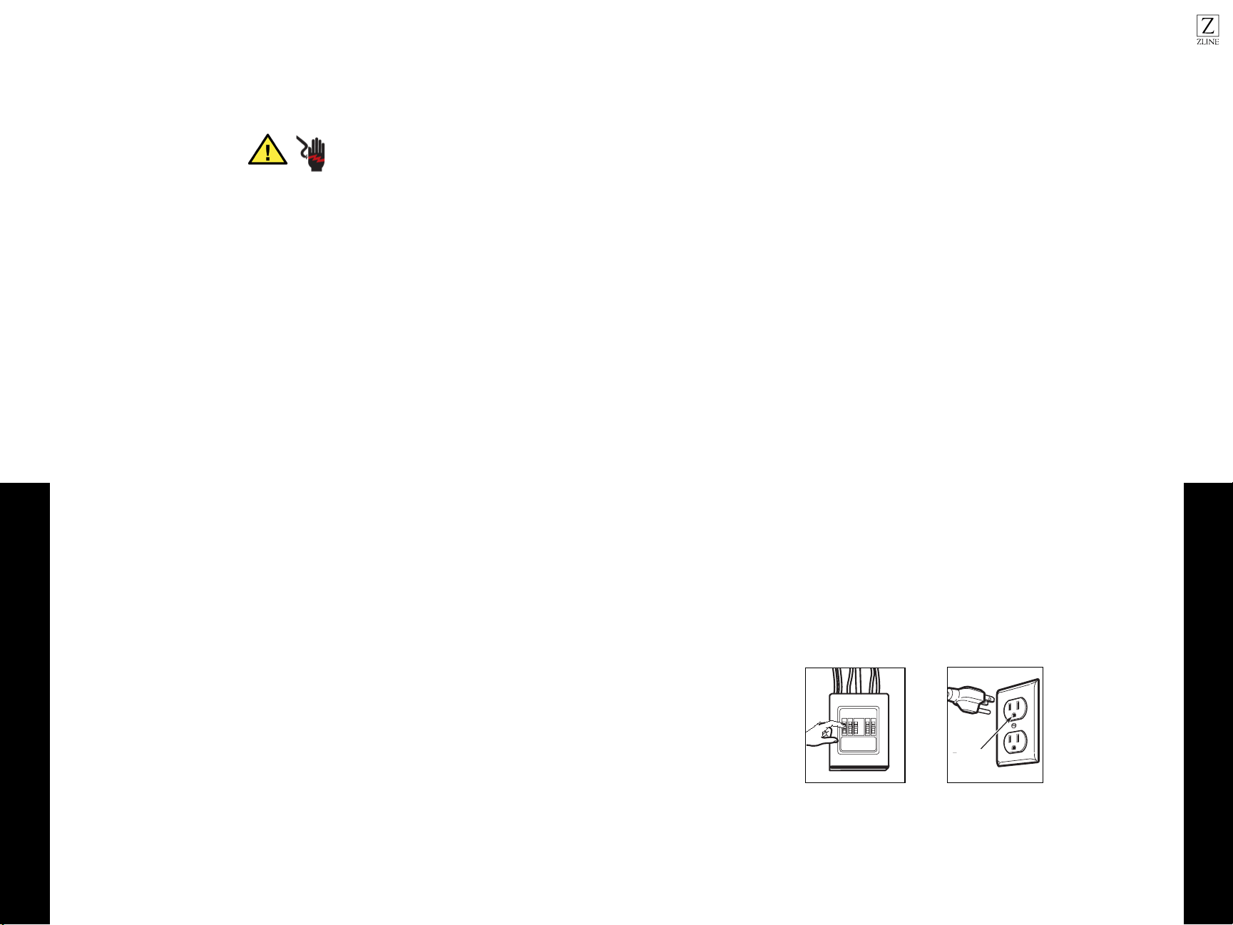
• For personal safety, remove house fuse or open circuit breaker before beginning
installation to avoid severe or fatal shock injury. Figure 1
• For personal safety, the mounting surface must be capable of supporting the
cabinet load, in addition to the added weight of this 63–85 pound (28.5–38.5
kg) product, plus additional oven loads of up to 50 pounds (22.7 kg) or a total
weight of 113–135 pounds (51.3–61.2 kg).
• For personal safety, this product cannot be installed in cabinet arrangements
such as an island or a peninsula. It must be mounted to BOTH a top cabinet
AND a wall.
• IMPORTANT – PLEASE READ CAREFULLY. FOR PERSONAL SAFETY, THIS
APPLIANCE MUST BE PROPERLY GROUNDED TO AVOID SEVERE OR FATAL
SHOCK.
• The power cord of this appliance is equipped with a three-prong (grounding)
plug which mates with a standard three-prong (grounding) wall receptacle to
minimize the possibility of electric shock hazard from this appliance. Figure 2
• You should have the wall receptacle and circuit checked by a qualified
electrician to make sure the receptacle is properly grounded.
• Where a standard two-prong wall receptacle is encountered, it is very important
to have it replaced with a properly grounded three-prong wall receptacle,
installed by a qualified electrician.
• DO NOT UNDER ANY CIRCUMSTANCES, CUT, DEFORM OR REMOVE
ANY OF THE PRONGS FROM THE POWER CORD. DO NOT USE WITH AN
EXTENSION CORD.
T
a
t
p
s
(
t
of
f
Ensure proper
ground exist s
before use
Figure 2
C
s
or
be
in
or
Figure 1
Ensure proper
ground exists before use
65
PARTS INCLUDED QUANTITY
Wood Screws (¼” and 2”) 2
Toggle Bolts (& Wing Nuts) (¼ ” x 3”) 2
Self-Aligning Machine Screws (¼-28” x 3¼”) 3
Nylon Grommet (for Metal Cabinets) 1
Top Cabinet Template 1
Rear Wall Template 1
Manual 1
Separately Packed Grease Filters 2
Exhaust adapter 1
Glass tray 1
Turntable ring 1
Convection Wire Rack 1
Shelf 1
PART
INSTALLATION
INSTRUCTIONS
USE & CARE
MANUAL
For some models
For some models
W
(
T
wing
Self-Aligning
Screws
Nylon
(for
16
Mounting Space
Parts & Tools
BEFORE INSTALLATION
.
BEFORE INSTALLATION
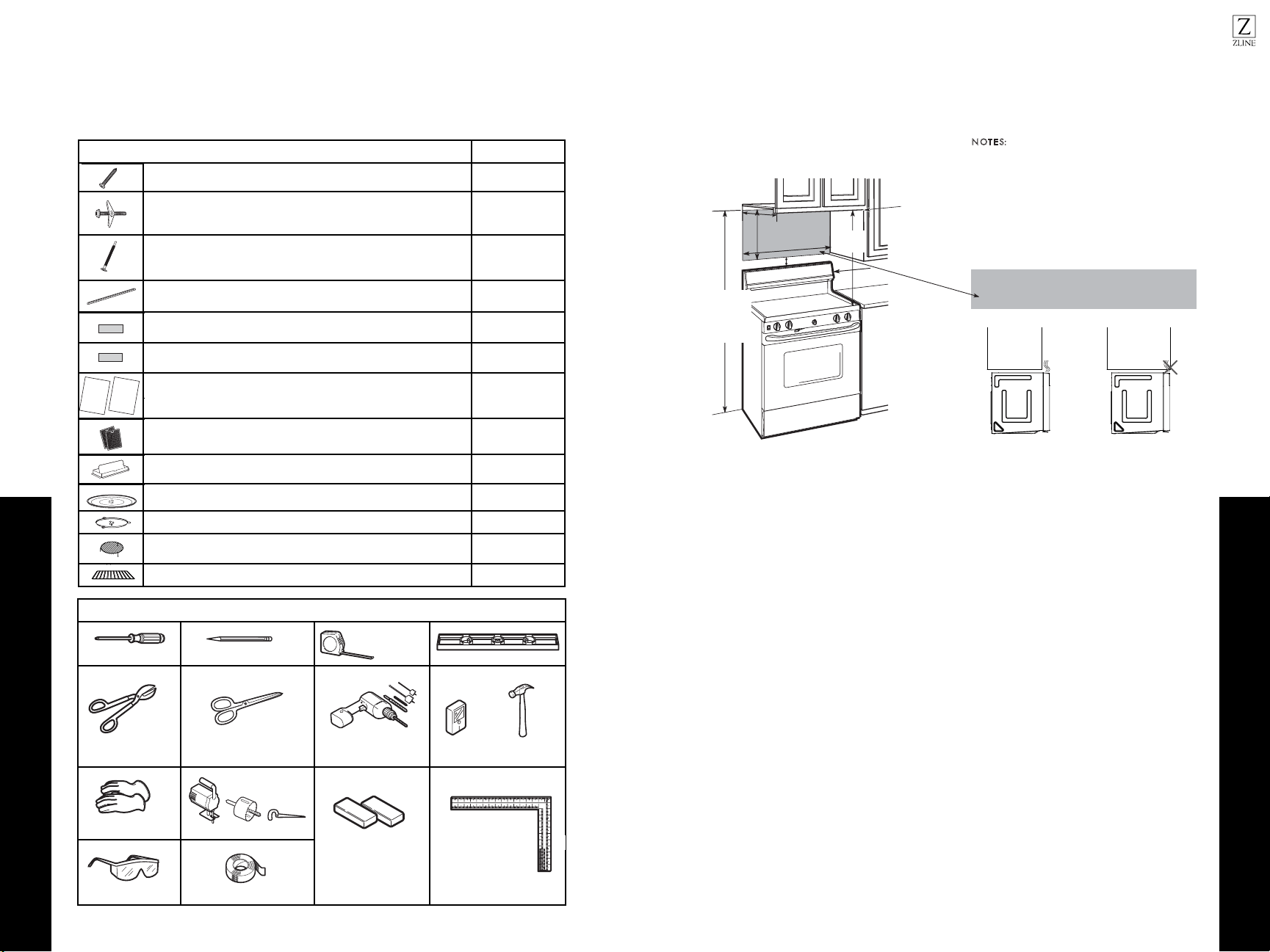
MOUNTING SPACE
N
OT E S:
•The space between the cabinets must be
30“ wide and free of obstructions.
•If you are going to vent your microwave oven
to the outside, see Hood Exhaust Section for
exhaust duct preparation.
•When installing the microwave oven beneath
smooth, flat cabinets, be careful to follow the
instructions on the top cabinet template for
power cord clearance.
Bottom Edge of
Cabinet Needs to
be 30”or More
from the Cooking
Surface
Backsplash
66”o
r More from
the Floor to the
Top of the
Microwave
30“
2”
18” min.
16
1
⁄2
“
13“ Maximum
As a guide to installation, see page 25 for Mounting
Template Information.
•
•
If the cabinet depth including the cabinet doors is more
than 13”, then the unit must be spaced out from wall
using adequate materials supporting 150 Ibs to allow
proper top vent air exhaust/intake.
TOOLS NEEDED
# 1 Phillips screwdriver
Tin snips (for cutting
damper, if required)
Gloves
Safety goggles
screwdriver
Pencil
Ruler or tape measure
and straight edge
Electric drill with
3
⁄16“,
1
⁄2“ and
5
⁄8“
drill bits
Hammer (optional)
Stud finder or
Duct and masking
tape
Scissors
(to cut template, if necessary)
Saw (saber, hole or keyhole)
Level
Filler blocks or scrap
wood pieces, if needed
for top cabinet spacing
(used on recessed bottom
cabinet installations only)
Carpenter square
(optional)
3
87
Placement of the Mounting Plate
Placement of the Mounting Plate
INSTALLATION
INSTALLATION
PLACEMENT OF THE MOUNTING PLATE
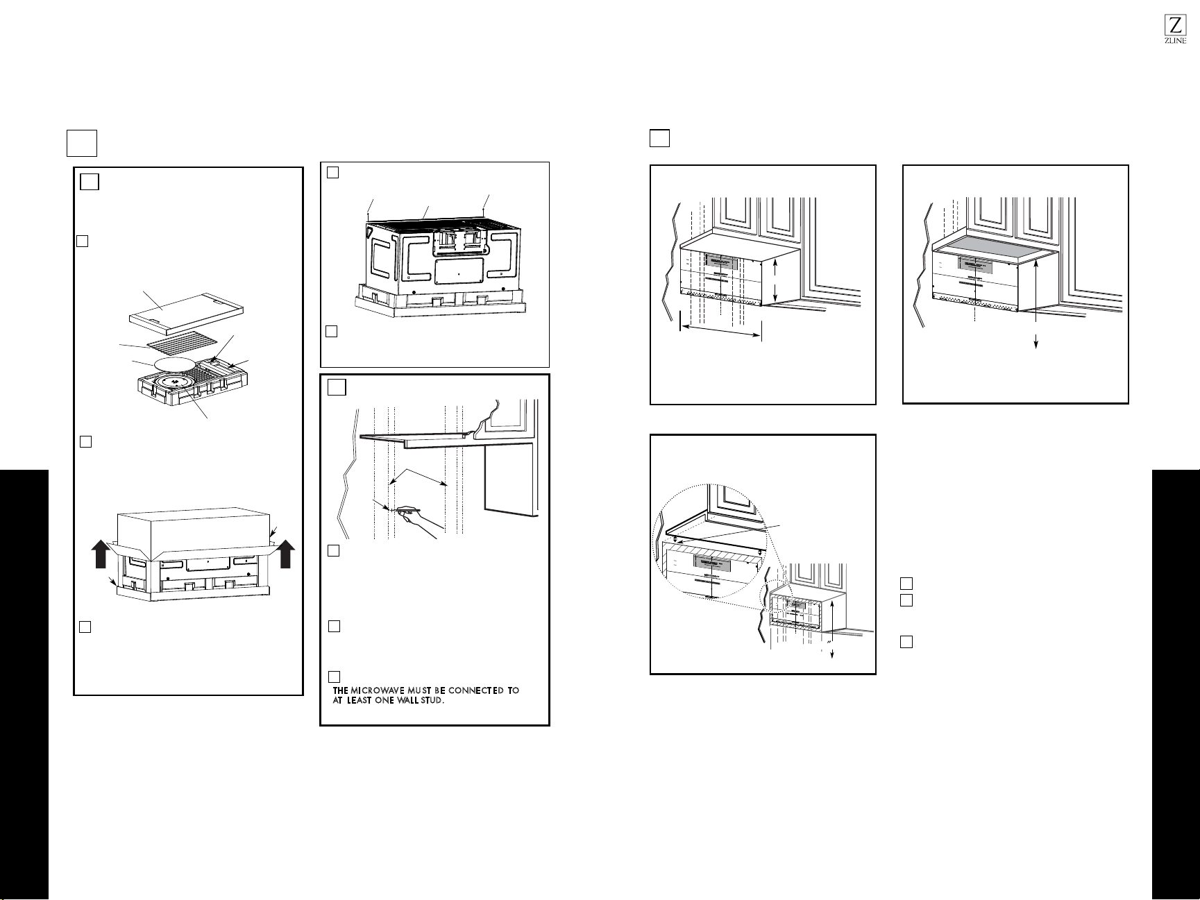
1
Find the studs, using one of the following
methods:
A. Stud finder–amagnetic device which
locates nails.
B. Useahammer to tap lightly across the
mounting surface to findasolid sound.
This will indicateastud location.
After locating the stud(s), find the center by
probing the wall withasmall nail to find the edges
of the stud. Then placeamark halfway between
the edges. The center of any adjacent studs should
be 16” or 24” from this mark.
Drawaline down the center of the studs.
T
HE MI CROWAVE MU ST BE CONNE CT E D TO
AT L E AST ONE WAL L STUD.
1
Fold back all4carton flaps fully against carton
sides. Then carefully roll the oven and carton over
onto the top side. The oven should be resting in
the Styrofoam.
REMOVING THE MICROWAVE
OVEN FROM THE CARTON/
REMOVING THE MOUNTING
PLATE
FINDING THE WALL STUDS
B
.
A
.
2
Wall
Studs
Center
3
Pull the carton up and off the oven.
2
3
5
4
Cut the middle of the outer protective plastic bag to
remove the mounting plate.
Remove the screws from each end of the mounting
p late. This plate will be used as the rear wall template
and for mounting. Reinstall the screws into the holes
where they were removed.
1
Exhaust Adapter
Filters and Turntable Ring below glass tray
Small Hardware Bag
Shelf (For
some models)
Remove the top cover board, installation
instructions, use and care, exhaust adapter,
turntable ring, shelf, filters, glass tray and the
Styrofoam protecting the front of the oven.
small hardware bag.
Top Cover Board
EPE Pad
Carton
Styrofoam
Screws
Screws
Mounting Plate
DETERMINING WALL PLATE LOCATION UNDER YOUR CABINET
C.
Plate position: beneath flat bottom cabinet
to Cooktop
C
3/
8"
T
O
E
DGE
NOTE: I
T IS VER
Y IMPORTANT T O
READ
A
ND F
O
LLOW TH
E
DIRECTIO
N
S
IN THE IN
S
T
A
L
L
ATION INSTRUCT
IO
N
S
BE
F
O
R
E
PROCEE
DING WITH
T
H
IS
REAR W
A
LL
TEMP
L
A
TE.
This
Rear Wall Te
m
pl
at
e
ser
v
e
s
to position
the botto
m
mountin
g
plate and
to lo
ca
t
e
t
he
ho
rizontal e
xh
aust
out
let.
1.
Use
a
level
t
o check
th
a
t the template
is p
o
s
itioned
a
ccurat
e
ly.
2. Locate and
m
ar
k
at
leas
t
one s
tud
o
n t
h
e
le
f
t
o
r
right
s
ide of t
h
e centerline.
It
is imp
ort
a
nt
t
o use at
le
a
st o
ne wood
screw m
ount
ed
f
ir
mly in a stud to s
u
ppor
t
the weight
of th
e
microwave. M
ark two
ad
d
itional,
ev
e
nly
s
paced
loca
t
ions for
the su
pplied toggle
bolt
s
.
3. D
r
ill holes
in the
m
arked
locat
ions.
Where there
is
a
stud, dr
ill a 3
/1
6
" hole f
o
r
wood screws
.
F
o
r holes
that
d
o not
li
ne up wit
h
a
s
t
ud
,
drill 5/8"
holes
for
togg
le
bolts.
D
O
NOT INSTALL
T
H
E
M
O
UNT
ING P
L
ATE
AT
TH
IS
TIM
E.
4.
Rem
ove the te
m
plate
f
rom t
h
e r
e
ar wall.
5.
R
e
view t
h
e Installation
I
nstruction book f
o
r your
installat
ion si
tuation.
L
o
c
a
t
e and m
a
rk h
o
l
es
to ali
g
n wit
h
ho
l
es in
the
mo
u
n
t
in
g p
l
a
te.
IMPORTA
NT
:
LO
C
ATE AT LEAS
T
ONE S
T
U
D ON EITH
ER
SIDE
O
F
T
HE CEN
TERLINE.
MARK
T
H
E
LOCAT
ION
F
OR
2 AD
D
IT
I
ONAL,
E
V
ENLY
SPAC
E
D TO
GGLE
B
OL
T
S
IN
THE
MO
UN
TING P
L
AT
E
A
RE
A
.
Locate a
nd
ma
r
k
hol
e
s to
a
l
ign with ho
l
es i
n
t
h
e
mountin
g
pl
a
te.
IMPO
RTA
N
T
:
LOCA
TE
A
T
L
EA
ST
ON
E
ST
U
D ON EITH
E
R SIDE OF
T
H
E
C
E
N
T
E
RLIN
E
.
MARK THE
L
OCA
T
I
ON
F
OR 2
AD
D
IT
IONAL
, EVENLY
S
P
A
CE
D TOGGLE BOLT
S
IN
T
H
E
MOUN
TING
P
LATE
AR
E
A.
T
rim th
e rea
r
wall te
m
p
l
a
te
alo
ng t
he d
otted line.
Trim
the r
ear
wa
ll
te
m
p
l
a
te
alo
n
g th
e
d
o
tted l
in
e.
12"
4"
D
arle
vu
e
lt
a a
la h
o
ja
para
c
on
s
u
lt
ar la
ve
r
sión
en E
spañol.
3/8
"
TO EDGE
N
O
TE:
I
T IS
VER
Y
IMPOR
TAN
T T
O
READ
AND FOLLO W TH E D IR
EC
TION
S
I
N
TH
E
INSTALL
ATION
INST
RUCTIO
NS
BEFO
R
E
PR
O
C
EEDING
W
ITH TH
I
S
R
EAR W
AL
L
T
EMPL
AT
E.
This Re ar Wall Te mp
late serves to
posit
i
o
n
the
bot
to
m
mou
ntin
g plate and to loc ate th e h oriz ontal e
x
ha
ust
outlet.
1. Use a
l
ev
el to check
th
a
t the templat e is
p
ositioned
accurately.
2. Loca
te
and
ma
rk
a
t least one s tu d on t he left o
r
r
ight side o
f
the centerlin e.
It is importan t to u s
e a
t least o
ne
wo
od
s
c
r
e
w mounted firmly in a s tu d to s u pport
the weigh
t
of the
mic
rowave. Mar
k two additio
nal, evenly s paced
locatio
ns for the s upp lied t oggle b o
lts.
3. Drill holes in the ma rke d
loc
ations
. Whe
re there is
a stud, drill
a 3/16" hole for w
ood sc
rews
. For ho
les
that do n
o
t line up
with a s
tud,
drill 5
/8" holes for
to
g
gle bolts.
DO NOT INSTAL L TH E MO
U
N
TING PLATE
AT THIS
TI
ME.
4. Re
m
ove
th
e te
mpla
te from the r ear w a
ll.
5. Revie
w
the Ins
ta
llation
In
struction book fo r your
installation situ atio n.
Locate an
d
ma
rk
holes to alig n wit h h oles
i
n the
mounti
ng plat
e
.
IMPORT
ANT:
LOC
ATE AT LEAST
ONE STUD
ON
EITHER SI
D
E OF
TH
E CENTER LINE.
MAR
K T
H
E
LOC
ATIO
N FOR 2
ADDITIONAL
,
EVEN
L
Y
SPAC
ED
TOGGLE BO
LTS I
N
THE MOUNT
I
NG
PLATE
AREA
.
Locate
and
ma
rk
h
ol
es t
o al
i
gn w
it
h
h
ol
es
in t
h
e
mo
untin
g pl
a
t
e.
IMPO
R
TANT:
LOC
AT
E AT
LEAS
T ON
E ST
U
D
ON EI
T
HER SID E OF
TH
E
CENTE R LIN
E
.
MARK T
HE LOCATIO N
F
O
R 2 AD
D
ITIONAL, EVEN LY
SPA
CE
D
T
O
G
GLE
BOL
T
S I
N
TH
E
MOUNTI
NG P
LATE
AR
EA.
Trim th e
rear
wall
templat
e
a
l
ong th e dotted
line.
Trim
the
r
ear wall
tem
plate al
ong
the
dotted li
ne.
12"
4"
D
arle
vuelt
a
a
la
h
oja par
a
consu lta
r
la
versión en E s pañ ol.
A
t
l
e
a
s
t
3
0
ʺ
C
3/8" TO EDGE
N
O
T
E
:
I
T IS
V
ER
Y IMPORT ANT
TO
READ A
N
D FOLLO W
THE
DIREC
TIONS
I
N T
HE
I
N
S
TAL
L
ATION I
N
STRU
C
TION
S
B
E
F
ORE P R OC
EE
D
ING WI
TH
TH
I
S
R
E
AR WALL T EM P
LAT
E
.
This
Rear Wa
l
l Template se rv
es to
p
os
i
tio
n the bo
t
to
m
mounting
pla
te and t
o
locate
the
ho
r
izontal
exhaust
o
utle
t
.
1. Use a level to ch
e
c
k
t
hat th
e
template is pos i
tioned
a
ccu
rately.
2
.
L
ocate and mark a
t
le
ast one stu d
on the left
o
r
right
sid
e of t
he
c
enterlin
e.
It is impor
ta
nt to use at leas t o ne wo o
d
scre
w
mo
unted firmly in a
s
t
ud to support the weigh t
of
t
he microwa
ve
.
Mark two
a
dditi
o
nal
, evenly
sp
aced
locations for th
e supplied
togg
le bo
l
t
s.
3. Drill holes in th
e
m
arke
d loca
t
ion
s.
Where there is
a stud, dril l a
3/16" h
o
le
for woo
d s
cre
w
s.
For holes
that do not lin
e
u
p
with
a
stud
, drill 5/8
"
holes for
togg
le
bo
lts
.
DO
NOT INSTAL L
T
HE
MOUNT
ING PLA
TE
AT TH
IS
T
IME.
4
. Remove t he tem p
late
from
the rear
wal
l.
5. Revi
ew the Ins
ta
l
lation In
stru
ction book for
your
installation
situation
.
Lo
cate and mar k
holes
t
o
al
ign w
ith holes
in t
h
e
m
o
unt
ing plate.
I
MP
ORT
A
N
T:
LO
C
ATE AT
LE
A
ST ON
E
S
TUD ON E
ITH
ER
S
I
DE
OF
TH
E C
EN
TERLI NE .
M
ARK TH
E
LOCATION
F
OR 2 A
D
D
I
TION
AL, EV ENL
Y
S
P
A
CED
TOGGL
E
BOLT
S IN THE
M
OUNTING P
LAT
E
A
REA.
Loc
at
e
a
nd
mar
k holes
t
o
align
w
ith holes
in
t
he
m
o
u
nt
i
ng plat
e
.
I
MPORTAN
T:
LOCATE AT LEA ST
ON
E
S
TUD
ON E
ITH
ER SI DE OF
TH
E CENT ER LI NE
.
MARK
T
H
E LOC
ATION F
OR
2
A
DD
I
TI
ON
AL,
EVE
NLY
SPA
C
ED
TOGGLE BOL T S
IN THE MOUNT ING
PLATE
ARE
A.
Trim
the re
a
r wall te m
pl
ate along
the
d
ot
ted
li
n
e.
Trim t h
e
rear
wa
ll
tem
p
l
a
t
e
a
l
ong
th
e
d
o
t
t
e
d
li
ne.
12"
4"
Da
rle
vuelta a la ho ja pa ra
c
on
s
ultar la
versión
en Espa
ñol.
Your cabinets may have decorative trim that
interferes with the microwave installation. Remove
the decorative trim to install the microwave properly
and to make it level.
THE MICROWAVE MUST BE LEVEL.
Measure the inside depth of the front overhang.
Draw a vertical line on the
wall at the center of the
30
ʺ wide space. Tape the
Rear Wall Template onto
the wall matching the
centerline and touching
the bottom of the cabinet.
Draw a vertical line on the wall at the center of the
30
ʺ space.
Tape the Rear Wall Template onto the wall matching the
centerline and touching the bottom cabinet frame.
C
3/
8"
TO ED
G
E
NOTE:
I
T
IS
VERY
IMPORT AN
T
TO
RE
A
D
A
ND F
OLLOW THE DIRE CTIONS
IN THE INS TALLA
TION I
NS
T
RUCT
I
ONS
BEFOR
E
PROCE E
D
ING
W
I
T
H
THIS
REAR W
A
LL
T
EMPL
ATE
.
This R
ear
Wa
ll Template se r ves to
position the b ott
om
mounting
p
late
and to locate t he
horiz
on
tal exhaust
outl
e
t
.
1
.
Use a l
e
ve
l
to
ch
eck that the
te
mplate is posi tion ed
accur
ately.
2
.
Locate a
nd
ma
r
k at le
ast o
n
e stud on th e le
ft or
r
i
ght side o
f
the
centerl
i
ne.
It
is importan
t to use
a
t
l
east one
wo
od
screw mo
u
nte
d
firmly in
a
stud
t
o su
ppo
rt
the we
ight
of the micro
w
ave. Mark
t
wo
ad
ditional
,
evenly spa
ce
d
l
o
cations for th e su ppli ed tog gle b
olts.
3. Drill holes
in
t
h
e m
ar
ked lo
cat
io
n
s. Where the re
is
a stud,
d
rill a
3/16"
h
ole
for woo
d
screws. F or ho l
es
t
h
at
d
o
not line up w
it
h
a stu
d, drill 5/8
"
h
oles fo
r
t
o
gg
le
b
o
lt
s
.
DO
NO
T IN
STALL
THE MOU
NTING PLAT E
AT TH
IS TIME.
4.
R
e
move th
e
t
emplate fr
o
m the rear wa ll.
5.
R
eview the Insta lla
tio
n I
n
struction book f or yo
ur
i
n
stallat
i
o
n situation.
Locat
e and
mark
hol
es
t
o align with
h
oles
i
n
the
mo
unti
ng
p
l
ate.
I
MPO
RTA
N
T:
LOCA
TE
A
T
LEAS
T
ONE
STUD
ON E
IT
HER S
IDE
O
F
THE
C
E
N
T
ER
LINE.
MA
RK T
HE
LOCATI
O
N
FOR 2 AD
DITIO
NAL, EVE NL Y
SP
A
CED TOGG LE
B
OLTS IN TH
E
MOUNTI
NG PLAT E
A
R
EA
.
Loc
a
t
e and mark ho
les
t
o align
w
i
th
hol
e
s i
n the
mo
unti
ng p
l
at
e.
IMPORT
ANT
:
LOCAT
E AT
LEAST ONE S T UD ON
EITHE
R SI
DE O
F
THE
CENTER L
I
NE.
MARK T
H
E
LOC
AT
ION FOR
2
A
DDIT
I
O
NAL, EVE NL
Y
SPACE
D TO
G
GLE
B
OLTS I
N THE
MOUNTING PL
ATE
A
REA.
Trim t
h
e
rear wa
l
l
temp
late
al
on
g the do tt e
d lin
e.
T
rim th e rea
r wall tem
p
l
a
te
al
o
ng th e do
tted lin
e
.
12"
4
"
Darle vue lt a a
la ho
ja para con s
ult
ar la
ve
rsión e n
E
s
p
año
l.
Plate position: beneath framed recessed cabinet
bottom
1
3
2
30” to Cooktop
30
For this type of installation with front overhang only,
align the mounting tabs with this horizontal line, not
touching the cabinet bottom as described in Step D.
16-1/2”
Draw a horizontal line on the back wall, an equal
distance below the cabinet bottom as the inside depth
of the front overhang.
Use a level to make sure the cabinet bottom is level.
If the cabinets have a front overhang only, with no back or
side frame, install the mounting plate down the same distance
as the front overhang depth. This will keep the microwave
level.
Plate position: beneath recessed bottom cabinet
with front overhang
Draw a line on the back
wall equal to the depth of
the front overhang.
109
Installation Types
INSTALLATION
INSTALLATION
ALIGNING THE WALL PLATE
D.
CAUTION: Wear gloves to avoid cutting fingers on sharp edges.
Area E
Hole A
Hole B
Centerline
notches
Draw a Vertical Line
on Wall from Center
of Top Cabinet
Draw a horizontal line on wall at the
bottom of “Rear Wall Template”.
Horizontal Line
Horizontal Line
C
L
3/8" TO EDGE
NOTE: IT IS VERY IMPORTANT TO
READ AND FOLLOW THE DI
RECTIONS
IN THE INSTALLATION INSTRUCTIONS
BEFORE PROCEEDI
NG WITH
THIS
REAR WALL TEMPLATE.
This Rear Wal l Template serves t
o position the bottom
mounting plate and to locate
the horizontal exhaust
outlet.
1. Use a level to check th
at the template is positioned
accurately.
2. Locate and ma
rk at least one stud on the left or
right side of the centerlin
e.
It is important to use at least one wood
screw mounted firmly in a stud to s
upport the weight
of the microwave. Mark two add
itional, evenly spaced
locations for the supp lied toggle bolts.
3. Drill holes in the marked locatio ns. Where there is
a stud, drill a 3/16" hole for wood screws. For hole
s
that do not line up with a st
ud, drill 5/8" holes for
toggle bolts.
DO NOT INSTALL THE M
OUNTING PLATE
AT THIS TIME.
4. Remove the tem plate from the rear wall.
5. Review the Installation Instru
ction book for your
installation situation.
Locate and mark
holes to align with h
oles in the
mounting plat
e.
IMPORTANT:
LOCATE
AT LEAST ONE
STUD ON EITHER SIDE OF
THE CENTERLINE.
MARK THE LOCATION FOR 2
ADDITIONAL, EVENLY
SPACED
TOGGLE BOLTS IN
THE MOUNTING PLATE
AREA.
Locate and mark
holes to align with hol
es in the
mounting plat
e.
IMPORTANT:
LOCATE
AT LEAST ONE
STUD ON EITHER SIDE OF
THE CENTERLINE.
MARK THE LOCATION FOR 2
ADDITIONAL, EVENLY
SPACED
TOGGLE BOLTS IN
THE MOUNTING PLATE
AREA.
Trim the rear
wall template al
ong the dotted
line.
12"
4"
Darle vuelta a la hoja para consultar la
versión en Español.
Draw a vertical line on the wall at the center of the
30" wide space.
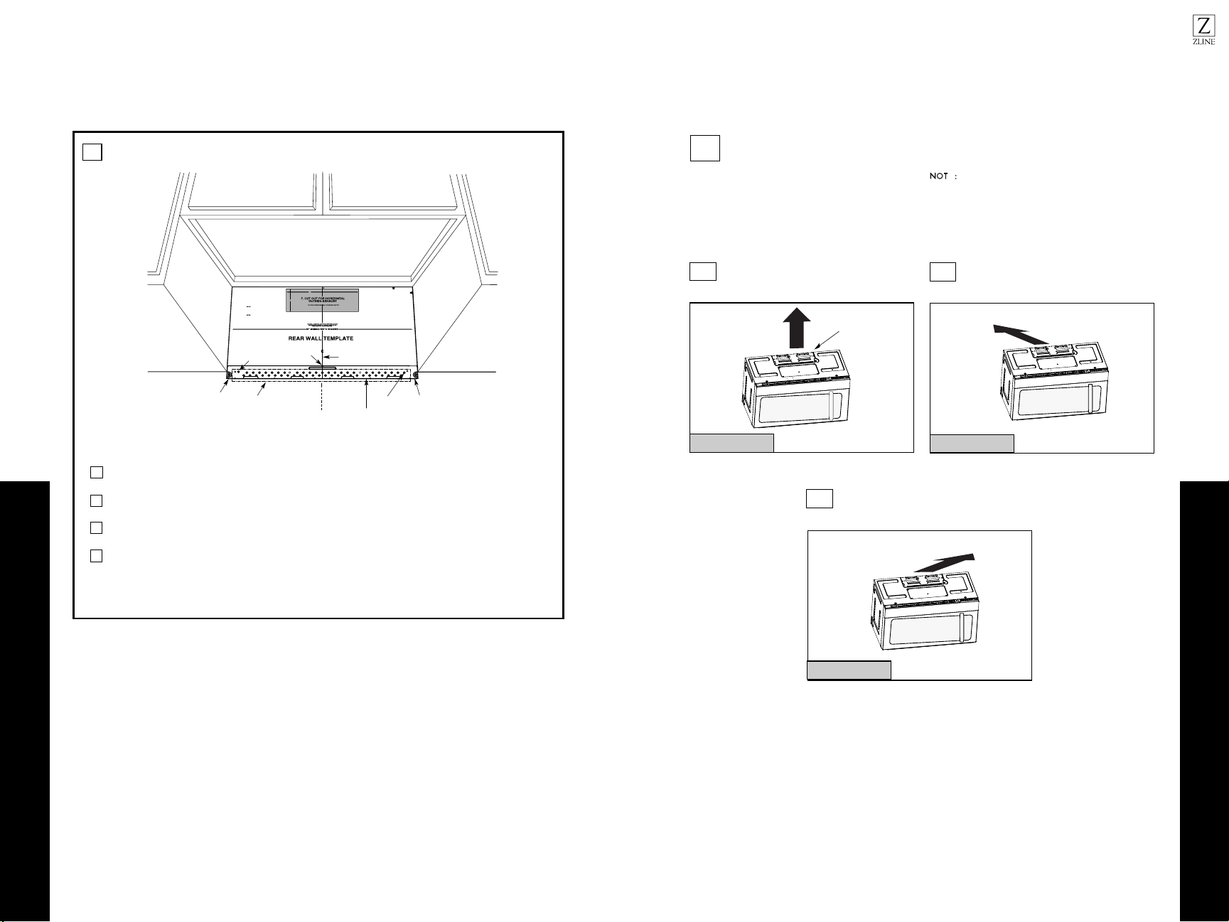
NOTE: DO NOT MOUNT THE PLATE AT THIS
TIME.
NOTE: Holes A and B are inside area E. If neither of
important to have at least one wood screw mounted
firmly in a stud to support the weight of the microwave.
microwave. Set the mounting plate aside.
1
2
Draw a horizontal line on the wall at the bottom of
“Rear Wall Template”.
Holes A and B are not in a stud, find a stud somewhere
in area E and draw a circle to line up with the stud. It is
3
Find a wall stud in area "E" of mounting plate
Refer to section 1B. Finding the wall studs.
For attaching the mounting plate into stud drill
a 3/16" hole into wood stud. Drill a 5/8" hole for
toggle bolt in 1 other location (Hole A or Hole B)
4
A
INSTALLATION TYPES
This microwave oven is designed for adaptation to
the following three types of ventilation:
A. Outside Top Exhaust (Vertical Duct)
B. Outside Back Exhaust (Horizontal Duct)
C. Recirculating (Non-Vented Ductless)
OUTSIDE TOP EXHAUST
(VERTICAL DUCT)
OUTSIDE BACK EXHAUST
(HORIZONTAL DUCT)
RECIRCULATING
(NON-VENTED DUCTLESS)
See page 12
recirculating exhaust.
disposable charcoal filter
installed to help remove
smoke and odors.
Adapter in Place for
Outside Top Exhaust
2
B
C
Adapter Must Be
Moved to the Back for
Outside Back Exhaust
N
OTE : This microwave is shipped assembled for
Recirculating. Select the type of ventilation required
(Choose A,Bor C)
for your installation and proceed to that section.
See page 16
See page 20
Models are shipped for
Some models have a
NOTE: Read the next two pages only if you plan to vent your exhaust to the
outside. If you plan to recirculate the air back into the room, proceed to page 20.
Placement of the Mounting Plate
1211
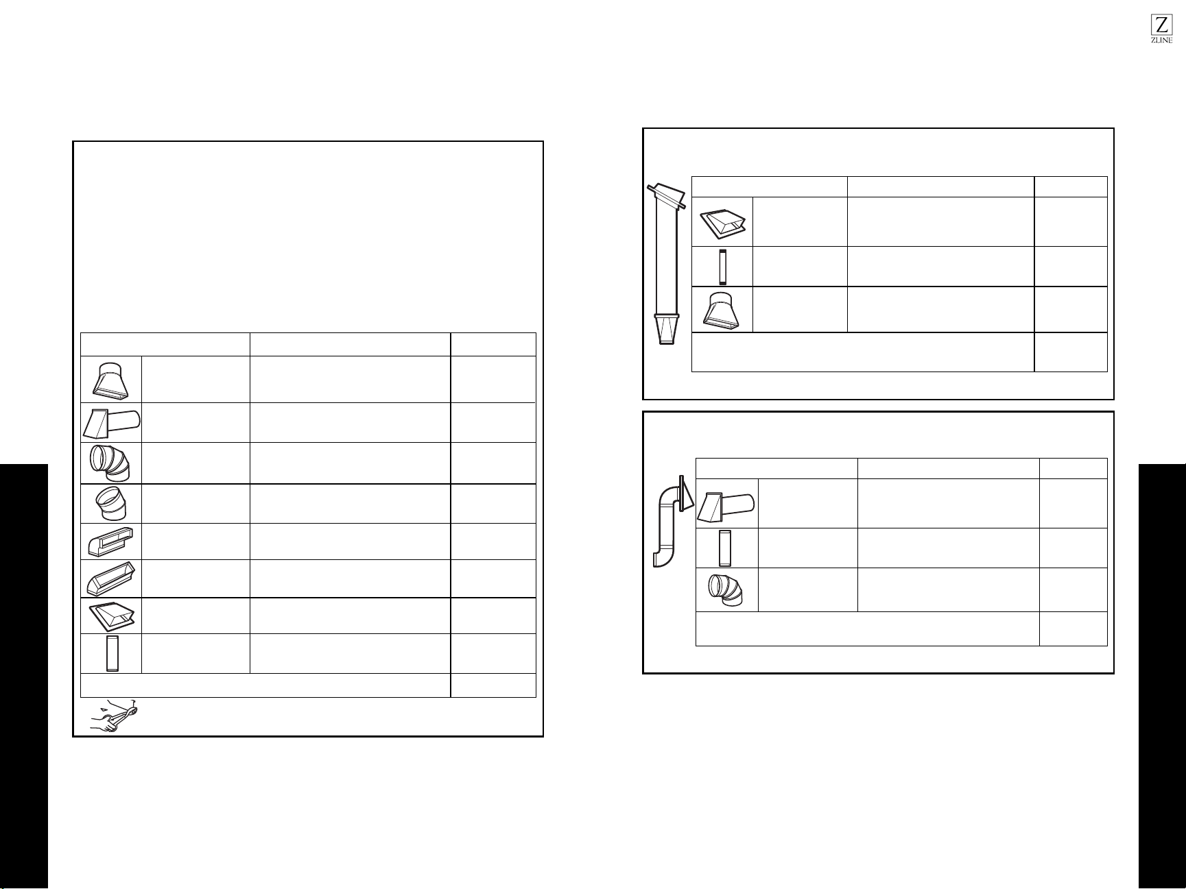
External Exhaust Ducting
External Exhaust Ducting
INSTALLATION
INSTALLATION
EQUIVALENT NUMBER EQUIVALENT
DUCT PIECES
LENGTH
x
USED
=
LENGTH
Rectangular-to-Round 5 Ft. (1.5 m) x ( ) = Ft. or m
Transition Adapter*
Wall Cap 40 Ft. (12.2 m) x ( ) = Ft. or m
90° Elbow 10 Ft. (3 m) x ( ) = Ft. or m
45° Elbow 5 Ft. (1.5 m) x ( ) = Ft. or m
90° Elbow 25 Ft. (7.6 m) x ( ) = Ft. or m
45° Elbow 5 Ft. (1.5 m) x ( ) = Ft. or m
Roof Cap 24 Ft. (7.3 m) x = Ft. or m
1 Ft. (0.3 m) x = Ft. or m
Straight Duct 6“ Round or 3
1/4" x 10“ Rectangular)
Total Ductwork = Ft. or m
Equivalent lengths of duct pieces are based on actual tests
and reflect requirements for good venting performance with
any vent hood.
* IMPORTANT: If a rectangular-to-round transition
adapter is used, the bottom corners of the damper
will have to be cut to fit, using the tin snips, in order
to allow free movement of the damper
.
Maximum duct length:
For satisfactory air movement, the total duct length of 3
1/4" x 10” rectangular or 5” diameter/6” diameter
round duct should not exceed 120 equivalent feet.
Elbows, transitions, wall and roof caps, etc.
present additional resistance to airflow and are
equivalent to a section of straight duct which is longer
than their actual physical size. When calculating the total
duct length, add the equivalent lengths of all transitions
and adapters plus the length of all straight duct sections.
The chart below shows you how to calculate total
equivalent ductwork length using the approximate feet of
equivalent length of some typical ducts.
INSTALLATION INSTRUCTIONS FOR EXTERNAL EXHAUST DUCTING
NOTE: If you need to install ducts, note that the total duct
length of 3 1/4" x 10” rectangular or 5” diameter/ 6”
diameter round duct should not
exceed 120 equivalent feet.
Outside ventilation requires an EXTERNAL EXHAUST
DUCT. Read the following carefully.
NOTE: It is important that venting be installed using
the most direct route and with as few elbows as possible.
This ensures clear venting of exhaust and helps prevent
blockages. Also, make sure dampers swing freely and
nothing is blocking the ducts.
Exhaust connection:
The exhaust adapter has been designed to mate with
a standard 3 1/4" x 10” rectangular duct.
If a round duct is required, a rectangular-to-round
transition adapter must be used. A 5 ”/ 6” diameter
duct is acceptable to use.
( )
( )
EQUIVALENT NUMBER EQUIVALENT
DUCT PIECES
LENGTH x USED
= LENGTH
Roof Cap 24 Ft. (7.3 m) x (1) = 24 Ft. (7.3 m)
x (1) = 12 Ft. (3.6 m)
12 Ft. Straight Duct 12 Ft. (3.6 m)
(6” Round)
Rectangular-to-Round 5 Ft. (1.5 m) x (1) = 5 Ft. (1.5 m)
41 Ft. (12.4 m)
Transition Adapter*
Equivalent lengths of duct pieces are based on actual tests and
reflect requirements for good venting performance with any vent hood.
Total Length =
The following chart describes an example of one possible ductwork installation.
OUTSIDE TOP EXHAUST (EXAMPLE ONLY)
NOTE: For back exhaust, care should be taken to align exhaust with space between studs, or wall should be prepared
at the time it is constructed by leaving enough space between the wall studs to accommodate exhaust.
* IMPORTANT: If a rectangular-to-round transition adapter is used, the bottom corners of the damper
will have to be cut to fit, using the tin snips, in order to allow free movement of the damper.
The following chart describes an example of one possible ductwork installation.
OUTSIDE BACK EXHAUST (EXAMPLE ONLY)
EQUIVALENT NUMBER EQUIVALENT
DUCT PIECES LENGTH* x USED = LENGTH
Wall Cap 40 Ft. (12.2 m) x (1) = 40 Ft. (12.2 m)
3 Ft. (0.9 m) x (1) = 3 Ft. (0.9 m)3 Ft. Straight Duct
(3 1/4" x 10” Rectangular)
90° Elbow 10 Ft. (3 m) x
(2)
20 Ft. (6 m)
Equivalent lengths of duct pieces are based on actual tests and
reflect requirements for good venting performance with any vent hood.
Total Length =
63 Ft. (19.1 m)
EXTERNAL EXHAUST DUCTING
=
1413
Outside Top Exhaust
Outside Top Exhaust
INSTALLATION
INSTALLATION
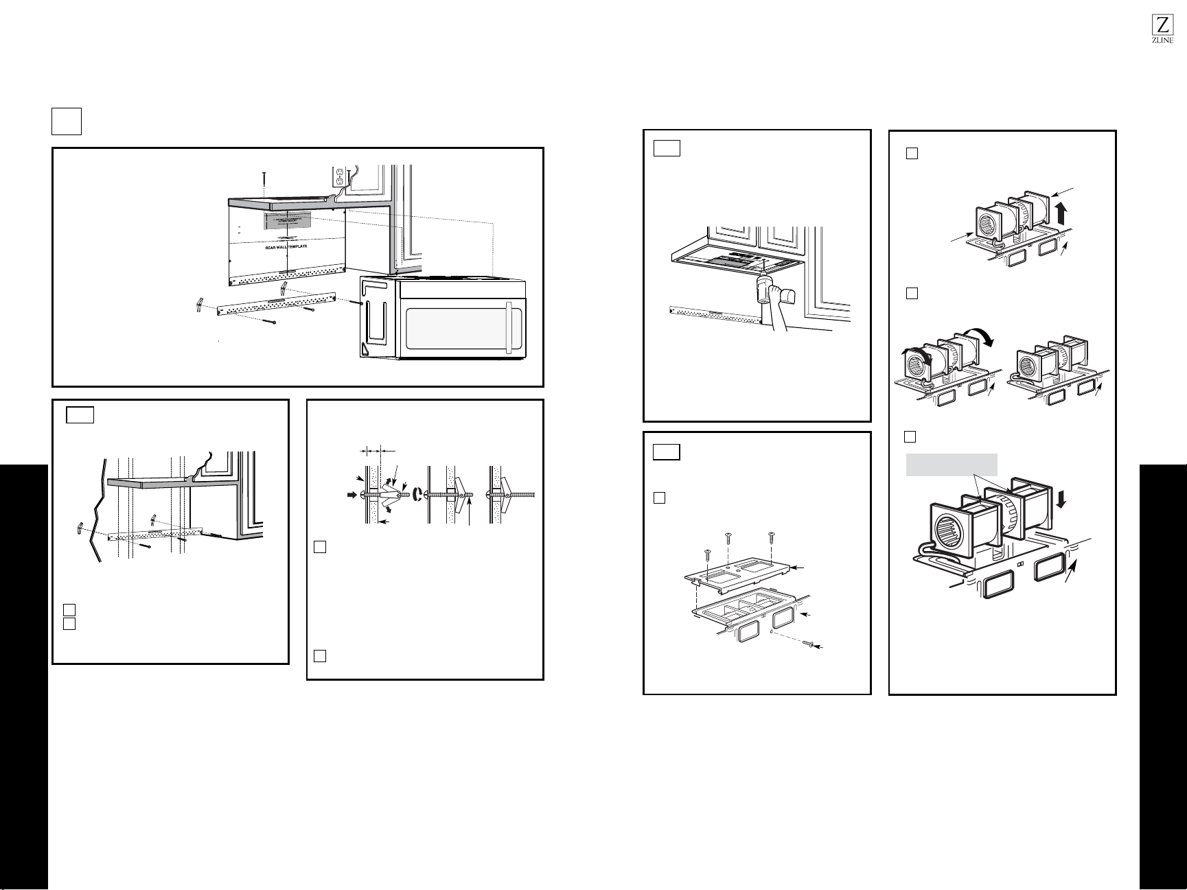
Place the mounting plate against the wall and
insert the toggle wings into the holes in the wall
to mount the plate.
NOTE: Before tightening toggle bolts and wood
screw, make sure the bottom of the mounting plate
touch the bottom of the cabinet when pushed
flush against the wall and that the plate is properly
centered under the cabinet.
CAUTION: Be careful to avoid pinching fingers
between the back of the mounting plate and the wall.
Tighten all bolts. Pull the plate away from the wall
to help tighten the bolts.
3
4
ATTACH THE MOUNTING
PLATE TO THE WALL
A1.
Attach the plate to the wall using toggle bolts.
At least one wood screw must be used to attach
the plate to a wall stud.
Remove the toggle wings from the bolts.
Insert the bolts into the mounting plate
through the holes designated to go into drywall
and reattach the toggle wings to 3/4" onto
each bolt.
1
INSTALLATION OVERVIEW
A1. Attach Mounting Plate to Wall
A2. Prepare Top Cabinet
Mount Microwave Oven
A5.
Adjust Exhaust Adaptor
A6.
Wall
Mounting
Plate
Spacing for Toggles
More Than Wall
Thickness
Bolt End
Toggle
Bolt
Toggle Wings
To use toggle bolts:
2
OUTSIDE TOP EXHAUST (Vertical Duct)
A
IMPORTANT NOTES:
•Make sure the screws for the
blower motor and blower plate
are securely tightened when
they are reinstalled. This will
help to prevent excessive
vibration.
•Make sure the motor wiring has
been properly routed and secured,
and that the wires are not pinched.
A7. Connect Ductwork
A3.
A4.
Check Damper Operation
Adapting Microwave Blower for
Outside Top Exhaust
12"
4"
NOTE: IT IS VERY IMPOR
TANT TO
READ AND FO
LLOWT HE DIRECTIO NS
IN THE INSTALLA TION INSTRU
CTI
ONS
BE
FORE PR O
CEEDING
WITH T HIS
REAR W ALL TEMPLA TE .
This R ea r Wall Te mpl ate s erves to p osition th e bottom
mounting plate a
nd to loc
ate the hor izon
ta
l exhaust
ou
tlet.
1. Use a lev
el
to
c
h
ec
k that the t
emplate is p os
itioned
accurately .
2. Loc
ate andmar k at leas t o u t s e
n
d on th r o t f e le
right s ide o f th e centerl ine.
It is importa nt to u se at leas t one wood
screw mo unted fi rmly in a s
tud
to supp
ort the we ight
of
the microwa ve. Mark t
w
o additional, ev en ly spa ced
locations f or the s uppl ied to ggle bol ts
.
3. Dri
ll holes in th e mark ed locatio ns.
Wher
e there is
a
s rd ,dut ill a 3/16" hole for wood sc rews . F or holes
that
do not lin h t i w pu
e a stud, d rill 5/8" holes for
toggle bolts .
DO
NOT INSTAL L T HE MOU NTING P L ATE
AT THIST IME.
4. Remov e th
e te
mplate from
the rear wall.
5.Re view the Ins ta
ll
a
t s n I n o i truc tion bo ok for y ou
r
install
a
tion situat ion .
Locate and m ark holes to align with holes in t
he
mounting
plate.
IMPORTANT :
LOCAT E AT LEAST ONE STUD
ON EI
THER SIDE OF
THE CENT ERLINE.
MARKT
HE LO
CATIONF OR 2 ADDIT
IO NAL, EV ENLY
SPACE D T
OGGLE
BOLTS IN THE MO UN
TING
PLATE
AREA.
Trim the r e
ar wall tem plat e along the do
tted line.
Darle vu elt a ala ho
ja
pa
rac ons ul tar la
v
e
rsión en E s paño l.
Locate and mar k
hole
s to ali gn with holes in t he
. e talp
g
n i tnu o m
IMPORTANT :
LOC
A
TE AT LEA ST O I E N O D U T S E NTHER SI D
E OF
THE
CENT
E
R
LI
N
E.
O
L E
H
TK R A MCATION FOR 2 ADDITION A L, EV ENL
Y
SPACED TOG GLE BO LTS IN THE MO UN
TING PLATE
AREA.
Trim the rear wall t em plat
e along
the dotted lin e.
3/8"TO EDG E
USE TOP CABINET TEMPLATE
FOR PREPARATION OF TOP
CABINET
You need to drill holes for the top support screws, a
hole large enough for the power cord to fit through,
and a cutout large enough for the exhaust adapter.
A2.
• Read the instructions on the TOP CABINET
TEMPLATE.
• Tape it underneath the top cabinet.
• Drill the holes, following the instructions on the
TOP CABINET TEMPLATE.
CAUTION: Wear safety goggles when drilling holes
in the cabinet bottom.
A3.
Remove the screw that holds the blower plate
to the microwave. Remove and save the screw
holding the blower motor to the microwave.
Blower Plate
Blower Motor
Screw
Back of
Microwave
2
Carefully pull out the blower unit. The wires
will extend far enough to allow you to adjust
the blower unit.
1
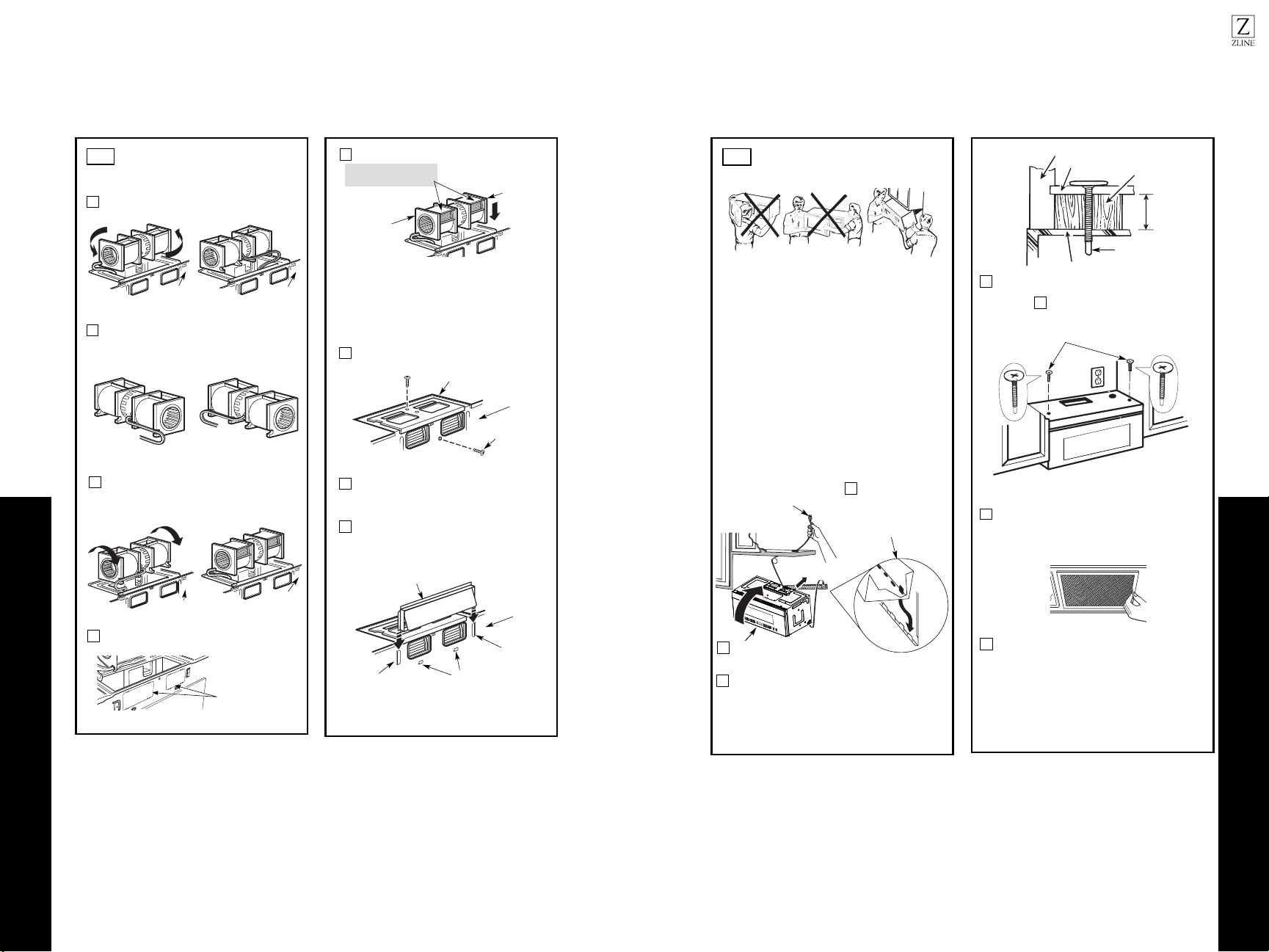
ADAPTING MICROWAVE
BLOWER FOR OUTSIDE
TOP EXHAUST
Roll the blower unit 90° so that fan blade
microwave.
3
Back of
Microwave
Before Rotation After Rotation
Back of
Microwave
openings are facing out the top of the
Back of
Microwave
AFTER: Fan Blade
Place the blower unit back into the opening.
Openings Facing Top
CAUTION: Do not pull or stretch the blower
unit wiring. Make sure the wires are not
pinched, and that they are properly secured.
4
with the top of the unit facing up.
Place the microwave in its upright position,
End B
End A
Back of
Microwave
1615
Outside Top Exhaust
Outside Top Exhaust
INSTALLATION
INSTALLATION
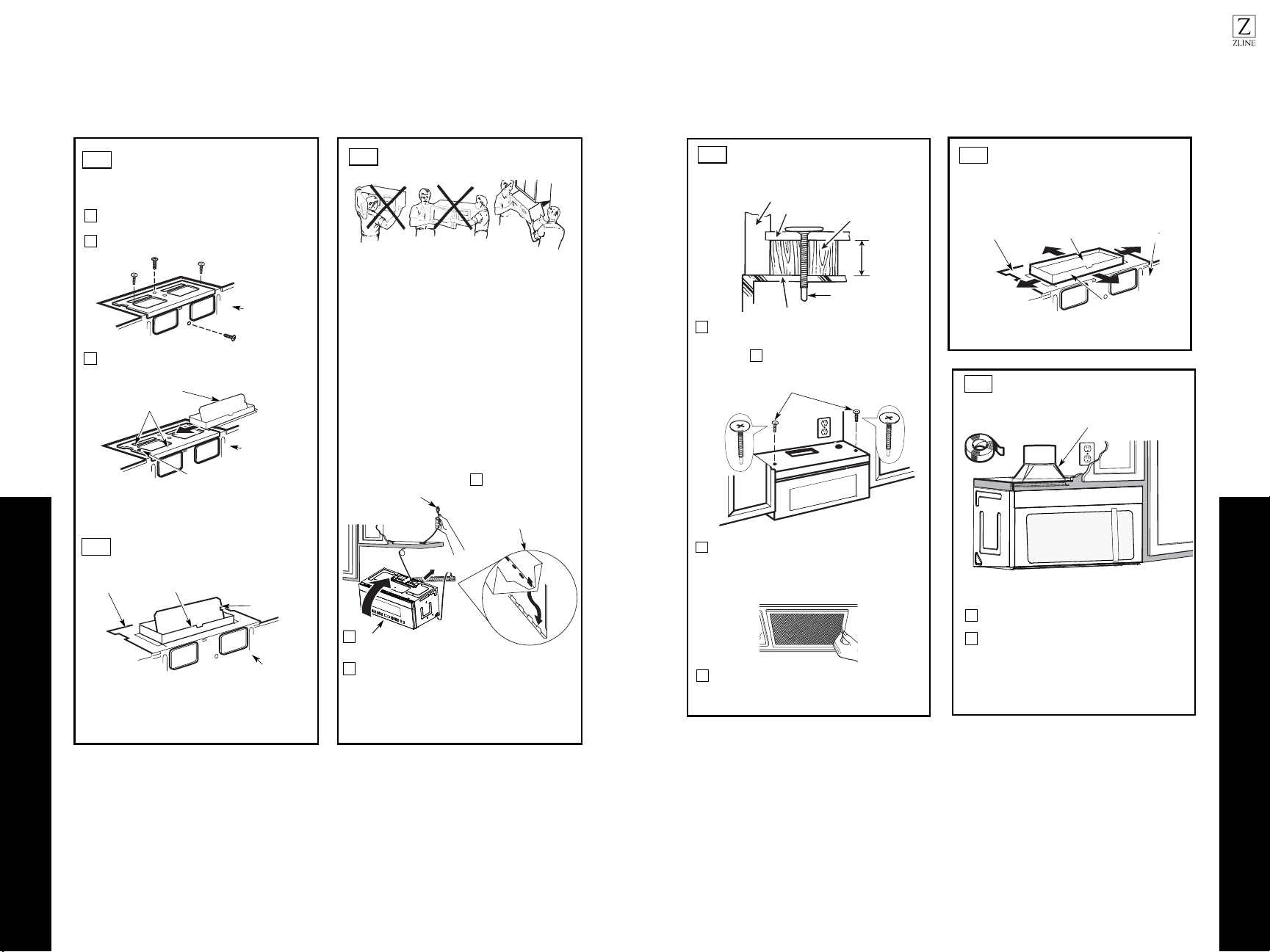
3
MOUNT THE MICROWAVE
OVEN
FOR EASIER INSTALLATION AND PERSONAL
SAFETY, WE RECOMMEND THAT TWO PEOPLE
INSTALL THIS MICROWAVE OVEN.
NOTE: If your cabinet is metal, use the nylon
grommet around the power cord hole to prevent
cutting of the cord.
NOTE: We recommend using filler blocks if the
cabinet front hangs below the cabinet bottom shelf.
IMPORTANT: If filler blocks are
not used, case damage may occur from
overtightening screws.
2
Rotate front of oven up against cabinet
bottom.
Insert a self-aligning screw through top center cabinet
hole. Temporarily secure the oven by turning the
screw at least two full turns after the threads have
engaged (it will be completely tightened later.) Be
sure to keep power cord tight. Be careful not to pinch
the cord, especially when mounting flush to bottom of
cabinet.
NOTE: When mounting the
microwave oven, thread
power cord through hole in
bottom of top cabinet. Keep
it tight throughout Steps
1–3. Do not pinch cord or
lift oven by pulling cord.
Lift microwave, tilt it
forward, and hook
slots at back bottom
edge onto four lower
tabs of mounting
plate.
1
CHECK FOR PROPER
DAMPER OPERATION
Exhaust Adaptor
Blower Plate
Damper
Back of
Microwave
•Make sure tape securing damper is removed
and damper pivots easily before mounting
microwave.
•You will need to make adjustments to assure
proper alignment with your house exhaust
duct after the microwave is installed.
A3.
ADAPTING MICROWAVE
BLOWER FOR OUTSIDE
TOP EXHAUST
Secure blower unit to microwave with the screw
5
removed in Step 1. Make sure the screw is tight.
Replace blower plate with the screw removed in
Step 1. Make sure the screw is tight.
Back of
Microwave
6
7
Back of
Microwave
Guide
Attach the exhaust adapter to the top of the
blower plate by sliding it into the guides of
the blower plate.
Adapter
Locking Tab
Push in securely until it is in the locking tabs.
Take care to assure that the damper hinge is
installed so that the damper swings freely.
A4.
A5.
IMPORTANT: Do not grip or use the handle
or heat shield during installation. Do not
remove the cardboard spacers between the
heat shield and door.
4
Attach the microwave oven to the top cabinet.
8
7
Cabinet Front
Cabinet Bottom Shelf
Tighten the outer two screws to the top of the
microwave oven. (While tightening screws, hold
the microwave oven in place against the wall and
the top cabinet.)
Filler Block
Microwave Oven Top
Equivalent
to Depth
of Cabinet
Recess
Insert 2 self-aligning screws
through outer top cabinet
holes. Turn two full turns on
each screw.
Install grease filters. See Use and Care
packed with the microwave.
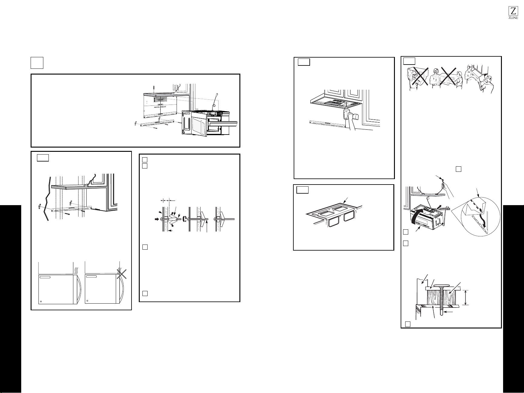
ADJUST THE EXHAUST
ADAPTER
Open the top cabinet and adjust the exhaust adapter
to connect to the house duct.
Back of
Microwave
For Front-to-Back or
Side-to-Side Adjustment,
Slide the Exhaust Adapter
as Needed
Blower Plate
Damper
Self-Aligning Screw
5
MOUNT THE MICROWAVE
OVEN (cont.)
A6.
A5.
CONNECTING DUCTWORK
1
2
A7.
Extend the house duct down to connect to the exhaust
adapter.
Seal exhaust duct joints using furnace duct tape
for
high temperature applications.
House Duct
1817
Outside Back Exhaust
Outside Back Exhaust
INSTALLATION
INSTALLATION
•
•
Remove and save the screw that holds the blower
plate to the microwave. Lift off the blower plate.
Back of
Microwave
P
P
R
R
E
E
P
P
A
A
R
R
I
I
N
N
G
G
T
T
H
H
E
E
R
R
E
E
A
A
R
R
W
W
A
A
L
L
L
L
F
F
O
O
R
R
O
O
U
U
T
T
S
S
I
I
D
D
E
E
B
B
A
A
C
C
K
K
E
E
X
X
H
H
A
A
U
U
S
S
T
T
B1.
You need to cut an opening in the rear wall for
outside exhaust.
• Read the instructions on the REAR WALL TEMPLATE.
• Tape it to the rear wall.
• Cut the opening, following the instructions of the
REAR WALL TEMPLATE.
B2.
OUTSIDE BACK EXHAUST (Horizontal Duct)
B
Blower Plate
R
R
E
E
M
M
O
O
V
V
E
E
B
B
L
L
O
O
W
W
E
E
R
R
P
P
L
L
A
A
T
T
E
E
I
I
N
N
S
S
T
T
A
A
L
L
L
L
A
A
T
T
I
I
O
O
N
N
O
O
V
V
E
E
R
R
V
V
I
I
E
E
W
W
B
B
1
1
.
.
Prepare Rear Wall
B
B
2
2
.
.
Remove Blower Plate
B
B
3
3
.
.
Attach Mounting Plate to Wall
B
B
4
4
.
.
Prepare Top Cabinet
B
B
5
5
.
.
Adjust Blower
B
B
6
6
.
.
Mount the Microwave Oven
I
I
M
M
P
P
O
O
R
R
T
T
A
A
N
N
T
T
N
N
O
O
T
T
E
E
S
S
:
:
3/8" TO EDGE
NO
TE: IT IS VE
RY IMPORT
ANT TO
READ AND FOLLOW THE DIRECTIONS
IN THE INSTALLATIO
N
INSTRUCTIONS
BEFO
RE PROCEED
ING WITH
THIS
REAR
WALL TEMPLATE.
This Rear Wall Templat
e serves to position the bottom
mounting plate and to locate the
horizontal exhaust
outlet.
1. Use a level to check t
hat t
he template is positioned
accurately.
2. Locate and mark at least one stud on the left or
right side of the centerline.
It is important to use at least one wood
screw mounted firmly in a stud to support the weight
of the microwave. Mark
two additional,
evenly spaced
locations for the supplied toggle bolts.
3. Drill holes in the marked locations. Where there is
a stud, drill a 3/16" hole f
or wood screws. For holes
that
do not line up wit
h a stud, drill 5/8" holes for
toggle bolts.
DO NOT INSTALL T
HE MOUNTING PLATE
AT THIS TIME.
4. Remove the template from the rear wall.
5. Review th
e Installation Instruction book for your
installation situation.
Locate and mark holes to align with holes in the
mounti
ng p
late
.
IMPORTANT:
LOCATE
AT LEAST ONE STU
D
ON EITH
ER SIDE OF
THE CENTERLINE.
M
A
RK THE LOC
ATION FOR 2 ADDITIONAL, EVENLY
SPACED TOGGLE BOLTS IN THE MOUNTING PLA
TE
AREA.
Locate and mark hol
es to
align with holes
in the
mounting
plate.
IMPORTA
NT:
LO
CATE AT LEAST ONE STUD O
N EIT
HER SIDE OF
THE CENTERLINE.
MA
RK THE L
OCATION FOR 2 ADDITIONAL, EVENLY
SPACED TOGG
LE BO
LTS IN THE MOUNTING PLATE
AREA.
Trim the rear wall template along the dotted line.
Trim the rear wall template alo
ng
the dotted line.
12"
4"
Darle vuelta a la hoja para consultar la
versión en Español.
Make sure the screws for the blower
motor and blower plate are securely
tightened when they are
reinstalled. This will help to
prevent excessive vibration.
Make sure the motor wiring has been
properly routed and secured, and
that the wires are not pinched.
12"
4"
NO
TE
: IT IS VERY IMPORTANT TO
READ AND FOLLO
WT NOI
T
C
ERIDEH S
IN THE INSTALLATION INSTRUCTIONS
BE
FO
RE PR
O
CEEDINGWITH TH
IS
REAR W
ALL TEMPLATE.
This RearWall Template serves to position the bottom
mou
nting plateand to locate th
e horizontal exhaust
outlet.
1. Use a levelto
c
heck th
at the t
emplate is positioned
accurately.
2. Locate andmark at least o utsen d on th ro tfele
right
side of the centerline.
It is important to use at least one wood
screw mounted firmly
in a stud to support the weight
ofthe microwave. Mark two additional, even
ly
spa
ced
locatio
ns for the supplied to
g
gle bolts.
3. Drill h
oles in th
e marked locations.Where there is
a stud, dril
l a 3/16" hole for wood scr
ews. F
or holes
thatdo
not lin ht
iwpu e a stud, drill 5/8" holes for
toggle bolts.
DO NOT INSTALL
T
HE MO
U
NTI
NG P
L
ATE
AT THISTIME.
4. Remove th
e template fromthe rear wall.
5.Reviewthe Installa tsnInoit ruction book for your
installation situation.
Locate and mark holes to align with holes in the
mounting
plate.
IMPORTANT:
LOCATE
AT LEAST ONE STUD ON EI
THERSIDE OF
THE CENT
ERLINE.
MARKT
HE LO
CATIONFOR 2 ADDITIONAL, EVENLY
SP
ACE
D T
OGGLE
BOLTS IN THE MOUNTING PLATE
AREA.
Trim the r
e
ar wall template alongthe dotted line.
Da
rlevuelta a la hoja para consul
tarla
versiónen Español.
Locate and mark
holes to align with holes in the
.etalpgnitnuom
IMPORTANT:
LOCATE AT LEAST O IE NO DUTSEN THER SI
DE OF
THE
CENT
E
R
LINE
.
OL EHTKRAM
CATION
FOR 2 ADDITIONA
L, EVENLY
SPACEDTOGGLE BOLTS IN THE MO
UN
TING PLATE
AREA.
Trim the rear wall template along
the dotted line.
3/8"
TOEDGE
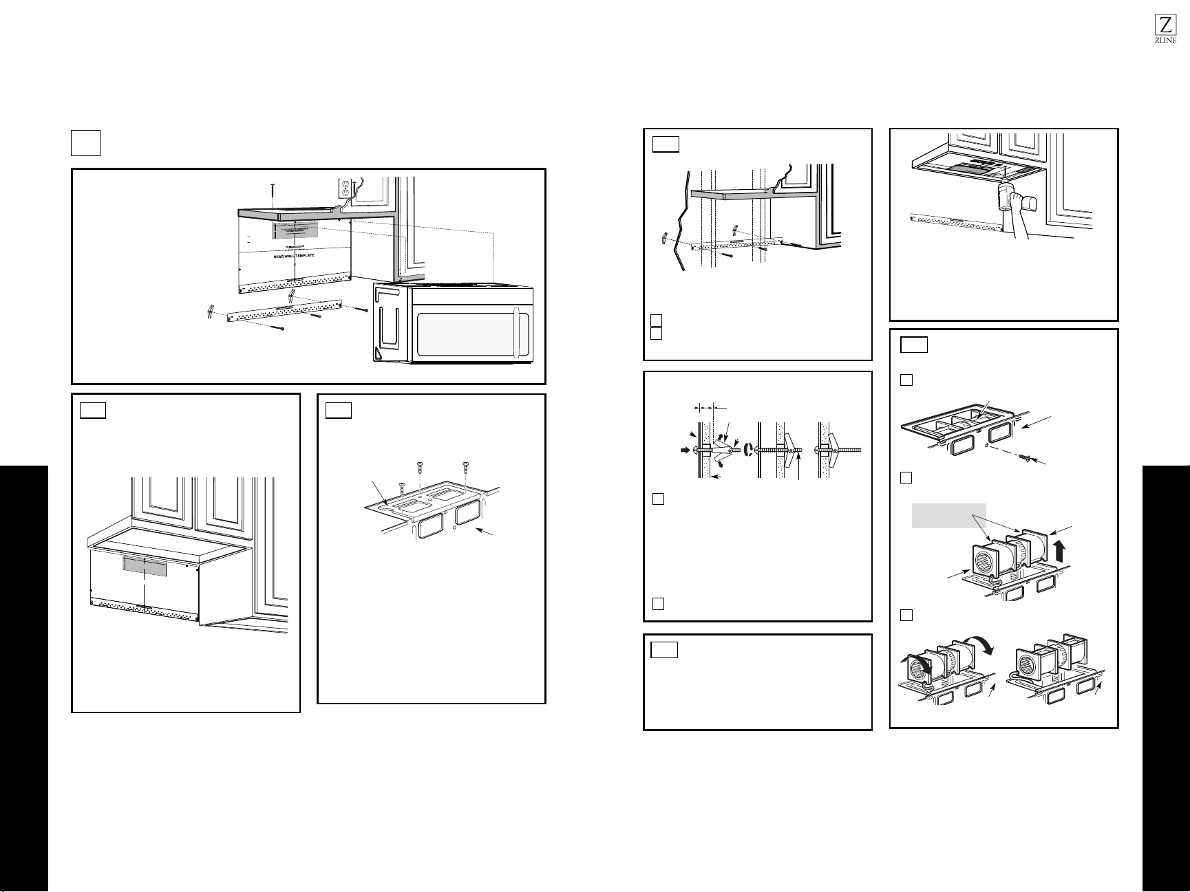
ATTACH THE MOUNTING
PLATE TO THE WALL
B3.
•
Read the instructions on the TOP CABINET
TEMPLATE.
•Tape it underneath the top cabinet.
•Drill the holes, following the instructions on the
TOP CABINET TEMPLATE.
CAUTION: Wear safety goggles when drilling holes in the
cabinet bottom.
Wall
Mounting
Plate
Spacing for Toggles More
Than Wall Thickness
Toggle
Bolt
Toggle Wings
To use toggle bolts:
Bolt End
Attach the plate to the wall using toggle bolts.
At least one wood screw must be used to attach the plate to
a wall stud.
Remove the toggle wings from the bolts.
Insert the bolts into the mounting plate through the holes
designated to go into drywall and reattach the toggle
wings3/4" onto each bolt.
1
2
Place the mounting plate against the wall and insert the
toggle wings into the holes in the wall to mount the plate.
NOTE: Before tightening toggle bolts and wood screw,
make sure the bottom of the mounting plate touch the
bottom of the cabinet when pushed flush against the wall
and that the plate is properly centered under the cabinet.
CAUTION: Be careful to avoid pinching fingers
between the back of the mounting plate and the wall.
Tighten all bolts. Pull the plate away from the wall
to help tighten the bolts.
3
4
2
1
Remove and save screw that holds blower motor
to microwave.
ADAPTING MICROWAVE
BLOWER FOR OUTSIDE
BACK EXHAUST
B5.
End B
End A
will extend far enough to allow you to adjust
the blower unit.
Back of
Microwave
Blower Motor
Blower Motor
Screw
Forward
Openings Facing
Carefully pull out the blower unit. The wires
Before: Fan Blade
USE TOP CABINET TEMPLATE
FOR PREPARATION OF TOP
CABINET
B4.
You need to drill holes for the top support screws and
a hole large enough for the power cord to fit through.
Back of
Microwave
Roll the blower unit 90°
Back of
Microwave
3
Before Rotation After Rotation
2019
INSTALLATION
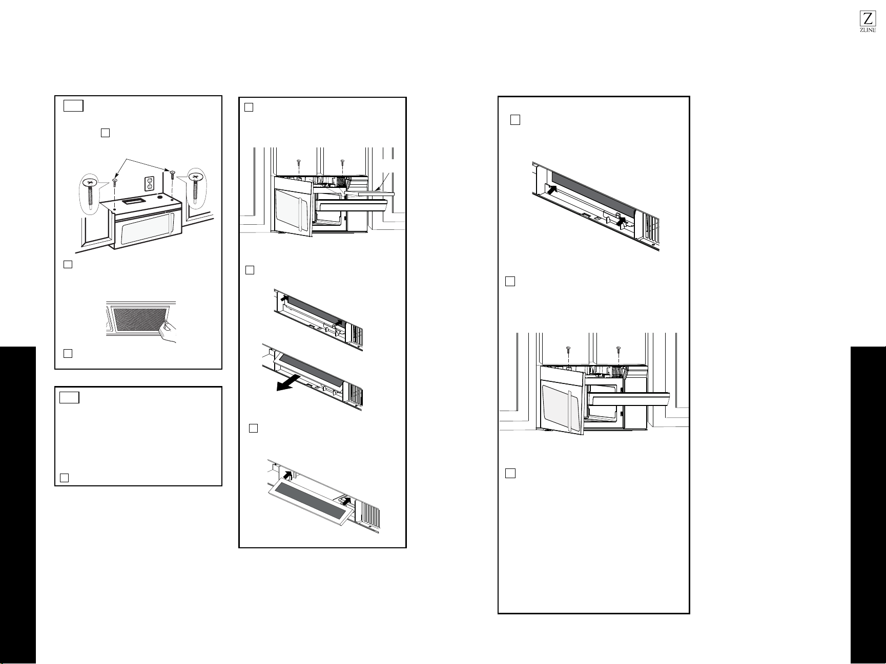
Attach the exhaust adapter to the rear of the
oven by sliding it into the guides at the top
center of the back of the oven.
AFTER: Fan Blade
Openings Facing Back
Place the blower unit back into the opening.
Replace the blower plate in the same position
as before with the screw. Make sure the screw
is tight.
Roll the blower unit 90° so that fan blade
openings are facing out the back of the
microwave.
ADAPTING MICROWAVE
BLOWER FOR OUTSIDE
BACK EXHAUST (cont.)
B5.
Rotate blower unit counterclockwise 180°.
Before Rotation After Rotation
Gently remove the wires from the grooves.
Reroute the wires through grooves on other side
of the blower unit.
Before Rerouting After Rerouting
Wires Routed Through Right Side
Wires Routed Through Left Side
Back of
Microwave
Back of
Microwave
Blower Plate
Blower Motor
Screw
Secure the blower unit to the microwave with
the original screw.
Before Rolling After Rolling
Back of
Microwave
End A
End B
Back of
Microwave
Back of
Microwave
CAUTION: Do not pull or stretch the blower
unit wiring. Make sure the wires are not
pinched, and that they are properly secured.
NOTE: The blower unit exhaust openings should
match exhaust openings on rear of microwave oven.
Push in securely until it is in the lower locking
tabs. Take care to assure that the damper hinge
is installed so that it is at the top and that the
damper swings freely.
Guide
Guide
Adapter
Locking Tabs
Back of
Microwave
4
5
6
11
Back of microwave
Knockout Plates:
Snip all 4 webs on
each knockout panel
and remove the metal
knockouts for rear airflow.
Please take care to
remove any sharp edges
created from removing
the knockout plates.
7
8
9
10
with snips. (For some models)
Remove the knockout plates in the back of the unit
INSTALLATION
Attach the microwave oven to the top cabinet.
3
MOUNT THE MICROWAVE
OVEN
B6.
FOR EASIER INSTALLATION AND PERSONAL
SAFETY, WE RECOMMEND THAT TWO PEOPLE
INSTALL THIS MICROWAVE OVEN.
NOTE: If your cabinet is metal, use the nylon
grommet around the power cord hole to prevent
cutting of the cord.
NOTE: We recommend using filler blocks if the
cabinet front hangs below the cabinet bottom shelf.
IMPORTANT: If filler blocks are not
used, case damage may occur from
overtightening screws.
Insert a self-aligning screw through top center
cabinet hole. Temporarily secure the oven by
turning the screw at least two full turns after the
threads have engaged. (It will be completely
tightened later.) Be sure to keep power cord
tight. Be careful not to pinch the cord, especially
when mounting flush to bottom of cabinet.
8
7
5
Cabinet Front
Cabinet Bottom Shelf
Tighten the outer two screws to the top of the
microwave oven. (While tightening screws, hold
the microwave oven in place against the wall and
the top cabinet.)
Filler Block
Microwave Oven Top
Equivalent
to Depth
of Cabinet
Recess
Insert 2 self-aligning screws
through outer top cabinet
holes. Turn two full turns on
each screw.
Self-Aligning Screw
4
2
Rotate front of oven
up against cabinet
bottom.
NOTE: When mounting the
microwave oven, thread
power cord through hole in
bottom of top cabinet. Keep
it tight throughout Steps
1–3. Do not pinch cord or
lift oven by pulling cord.
Lift microwave, tilt it
forward, and hook
slots at back bottom
edge onto four lower
tabs of mounting
plate.
1
Install grease filters. See Use and Care packed
with the microwave.
IMPORTANT: Do not grip or use the handle
or heat shield during installation. Do not
remove the cardboard spacers between the
heat shield and door.
Outside Back Exhaust
Outside Back Exhaust
2221
Recirculating
Recirculating
INSTALLATION
INSTALLATION OVERVIEW
C1. Attach Mounting Plate to Wall
C2. Prepare Top Cabinet
C4.
C5.
Mount the Microwave Oven
IMPORTANT NOTES:
•Make sure the screws for the blower motor and blower
plate are securely tightened when they are reinstalled.
This will help to prevent excessive vibration.
•Make sure the motor wiring has been properly routed
and secured, and that the wires are not pinched.
Place the mounting plate against the wall and
insert the toggle wings into the holes in the wall
to mount the plate.
NOTE: Before tightening toggle bolts and wood
scr ew make sure the bottom of the mounting plate,
touch the bottom of the cabinet when pushed flush
against the wall and that the plate is properly
centered under the cabinet.
CAUTION: Be careful to avoid pinching fingers
between the back of the mounting plate and the wall.
Tighten all bolts. Pull the plate away from the wall
to help tighten the bolts.
4
3
ATTACH THE MOUNTING
PLATE TO THE WALL
C1.
Attach the plate to the wall using toggle bolts.
At least one wood screw must be used to attach
the plate to a wall stud.
Remove the toggle wings from the bolts.
Insert the bolts into the mounting plate through
the holes designated to go into drywall and
1
Wall
Mounting
Plate
Spacing for Toggles
More Than Wall
Thickness
Bolt End
Toggle
Bolt
Toggle Wings
To use toggle bolts:
2
RECIRCULATING (Non-Vented Ductless)
C
Install or change Charcoal Filter
C3. Check Blower Plate
NOTE:
CabinetCabinet
If the cabinet depth including the cabinet doors
out from wall using adequate materials supporting
150 Ibs to allow proper top vent air exhaust/intake.
12
"
4"
NO
T
E
:IT I
S VER Y I MP
ORTANT T
O
R
EAD AN
D F
O
LL
O
W
T
H
E
DIRE
CTIONS
I
N
T
H
E
INST
ALL
ATIO
N
INS
TR
U
CTIO
N
S
BEF
OR
E PR
O
C
EE
D
I
NG
W
IT
H
T
HIS
RE
AR W
A
LL TE
MPLAT
E
.
Th
is Re
arWallTe
mp
la
t
e
serv
es to
p
o
sition
t
he b
o
ttom
moun
ti
n
g pl
a
tean
d tolocate
t
h
e
ho
rizontal
e
xhaus
t
outle
t.
1
.
Usea
lev
eltoch eck tha t th
e
te
mpla
t
e
isp
o
siti
on
e
d
a
c
c
urately.
2
. L
o
ca
te an
d
ma
rk at
least o
ne
stu
d
o
n
th
e lef
t
or
r
igh
t side o
f
thec
en
te
rline.
I
t
isimpo
rt
a
nt
t
o
u
s
e
at
le
a
st
one
wo
od
screwmou nte
d
fi
r
m
ly
in astud tosu
p
p
o
rt
t
he weight
of
the
m
icrowav
e
.
Mark
t
wo
additional,e
ve
n
lysp
aced
locationsfor the s uppliedt
oggle b
ol
ts.
3. Drill h
oles i
n
th
e marked loca
t
io
n
s
.
Wh
e
re thereis
a stud
,
d
rill
a
3/16
"
h
o
l
efor
wood
sc
rews. F
o
rhole
s
th
a
t
do
not
lin
e u
p
with a
stud
, drill5
/8
"
h
o
le
s
for
to
g
gle bolts.
DO NO
T
I
N
S
TALL TH
E
M
OUNTINGPL ATE
A
T
THIS TIME.
4
. Re
m
o
ve
t
h
e
template from t he rea
r
w
a
l
l
.
5
. Review the
I
n
st
a
l
lat
i
on
In
structi
onbook for yo
u
r
installation situ a
tion.
Loc
a
teand
ma
rk holes to
a
lign with holes in the
mounting plate.
I
MPORT
ANT:
LOCA
TE AT L
E
AST ONE STUD
ON EI
T
H
ER SIDE
OF
THE
CE
N
TE
R
L
I
NE.
MARK T
HEL
O
CA
TION F
O
R2 ADDI TI ONAL, EV EN L Y
SPACED TO
GGLE BOLT S
IN TH
E
MOUN
TING
PLATE
A
REA
.
L
oc
at
e
a
nd
mark hole
s
t
o al
i
gn
wi
t
h hol
es
int
h
e
m
o
un
tin
g
p
lat
e.
IMP
O
RT
A
NT
:
LO
C
AT
E
AT LEA ST
O
NE
ST
UD
ON EITHER SIDE
O
F
T
H
E
CENT
E
RLINE.
MA
RK
T
H
E
LOCA
TION F
O
R
2
A
D
DIT
ION
AL
,
EVENLY
SPACED TO G
G
LE
BO
L
TS
IN
T
H
E
MOUNT
INGPLA T E
AREA.
T
r
im
th
e
re
ar
wa
ll t
e
m
plate
alon
g
the
d
o
t
ted
li
n
e.
Da
r
levuel ta alaho
ja
para
consul
t
arla
v
ers
ió
n
e
nEs
p
añol.
3
/8"
T
OEDG E
Trim t he rear wal l t
em
pla
t
e along
t
h
e dotted lin
e
.
reattach the toggle wings to 3/4” onto each bolt.
is more than 13”, then the unit must be spaced
INSTALLATION
Installation Instructions
Attach the microwave oven to the top cabinet.
Cabinet Front
Cabinet Bottom Shelf
Filler Block
Microwave Oven Top
Equivalent to Depth
of Cabinet Recess
3
MOUNT THE MICROWAVE OVEN
FOR EASIER INSTALLATION AND PERSONAL
SAFETY, WE RECOMMEND THAT TWO PEOPLE INSTALL
THIS MICROWAVE OVEN.
NOTE: If your cabinet is metal, use the nylon grommet around
the power cord hole to prevent cutting of the cord.
NOTE: We recommend using filler blocks if the cabinet
front hangs below the cabinet bottom shelf.
IMPORTANT: If filler blocks are not used, case damage may
occur from overtightening screws.
Insert a self-aligning screw through top center
cabinet hole. Temporarily secure the oven by turning the
screw at least two full turns after the threads have engaged.
(It will be completely tightened later.) Be sure to keep power
cord tight. Be careful not to pinch the cord, especially when
mounting flush to bottom of cabinet.
.
Self-Aligning Screw
4
2
Rotate front of oven up against
cabinet bottom.
Lift microwave, tilt
it forward, and hook
slots at back bottom
edge onto four lower
tabs of mounting
plate.
1
C3.
C4.
CHECK BLOWER PLATE
Blower Plate
•Place the microwave in its upright position, with the
top of the unit facing up.
•Check to see that the blower plate is correctly
installed on the unit.
USE TOP CABINET TEMPLATE
FOR PREPARATION OF TOP
CABINET
C2.
•Read the instructions on the TOP CABINET
TEMPLATE.
•Tape it underneath the top cabinet.
•Drill the holes, following the instructions on the
TOP CABINET TEMPLATE.
CAUTION: Wear safety goggles when drilling holes
in the cabinet bottom.
You need to drill holes for the top support screws and
a hole large enough for the power cord to fit through.
Adjust top template accordingly if the microwave
NOTE:
IMPORTANT: Do not grip or use the handle or heat shield
during installation. Do not remove the cardboard spacers
between the heat shield and door.
NOTE: When mounting the microwave oven, thread
power cord through hole in bottom of top cabinet. Keep
it tight throughout Steps 1–3. Do not pinch cord or lift oven
by pulling cord.
is being spaced out from the wall due to cabinet depth
(including cabinet doors) of more than 13”.
2423
INSTALLATION
5
MOUNT THE MICROWAVE
OVEN (cont.)
8
7
Tighten the outer two screws to the top of the
microwave oven. (While tightening screws, hold
the microwave oven in place against the wall and
the top cabinet.)
Insert2self-aligning screws
through outer top cabinet
holes. Turn two full turns on
each screw.
packed with the microwave.
C4.
e the Use and CareeS .sretlif esaerg llatsnI
C5.
INSTALLING OR CHANGE
THE CHARCOAL FILTER
Unplug microwave oven or disconnect power.
1
NOTE: The charcoal filter is factory installed in some
models. Refer to the Use and Care to see if yours is
factory installed and for replacement information.
For models without the recirculation filter access
3
Open the microwave door and remove the two
eht fo pot no detacol; swercs gnitnuom tnev
microwave using a #1 Phillips screwdriver.
2
4
Remove the charcoal filter by pushing the
top of the filter inwards,then pull it forward
out from the unit.
Slide the top of the new charcoal filter into the
top of the filter cavity.
door, follow these steps to replace or install a charcoal
filter.
Charcoal
Filter
INSTALLATION
Close the microwave door. Plug in microwave
oven or reconnect power.
Reinstall the vent by sliding the bottom of the
vent into place. Push the vent top into position
and slide right into place. Replace the two vent
mounting screws located on top of the microwave
using a #1 Phillips screwdriver.
Press the bottom of charcoal filter to place it
into the correct position.
5
6
7
Recirculating
Recirculating
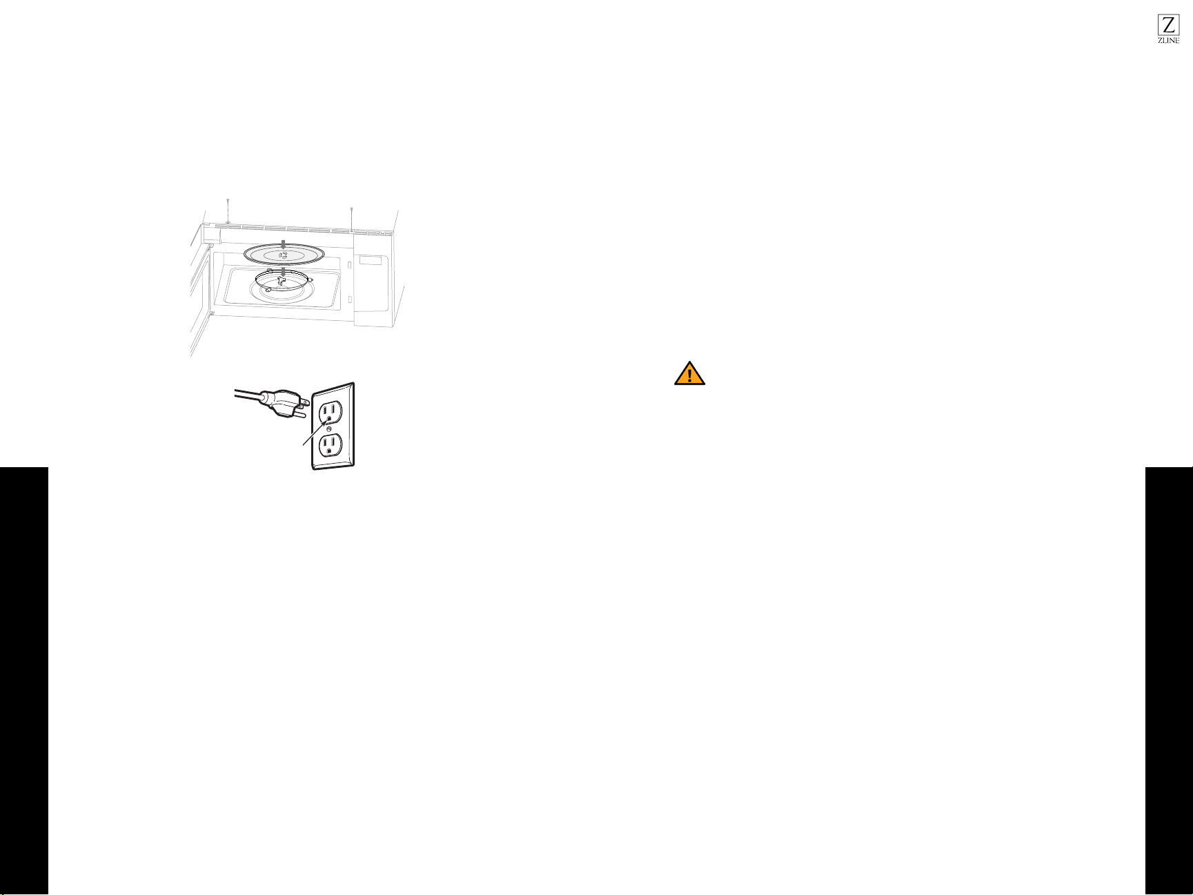
2625
Final Steps
Radio Interference
INSTALLATION
1. Make sure the microwave oven has been installed according to instructions.
2. Remove all packing material from the microwave oven.
3. Install turntable ring and glass tray in cavity.
4. Plug power cord into a separate and dedicated 15- to 20-amp electrical outlet.
5.
Ensure proper
ground exists
before use
Replace house fuse or turn breaker back on.
OPERATION
• Operation of the microwave oven may cause interference to your radio, TV, or
similar equipment.
• When there is interference, it may be reduced or eliminated by taking the
following measures:
• Clean door and sealing surface of the oven.
• Reorient the receiving antenna of radio or television.
• Relocate the microwave oven with respect to the receiver.
• Move the microwave oven away from the receiver.
• Plug the microwave oven into a different outlet so that microwave oven
and receiver are on different branch circuits.
Personal injury hazard
• Tightly-closed utensils could explode. Closed containers should be opened and
plastic pouches should be pierced before cooking.
• There may be certain non-metallic utensils that are not safe to use for
microwaving. If in doubt, you can test the utensil in question by following the
procedure below
• Fill a microwave-safe container with 1 cup of cold water along with
the utensil in question.
• Cook on maximum power for 1 minute.
• Carefully feel the utensil. If the empty utensil is warm, do not use it for
microwave cooking.
• Do not exceed 1 minute cooking time.
CAUTION
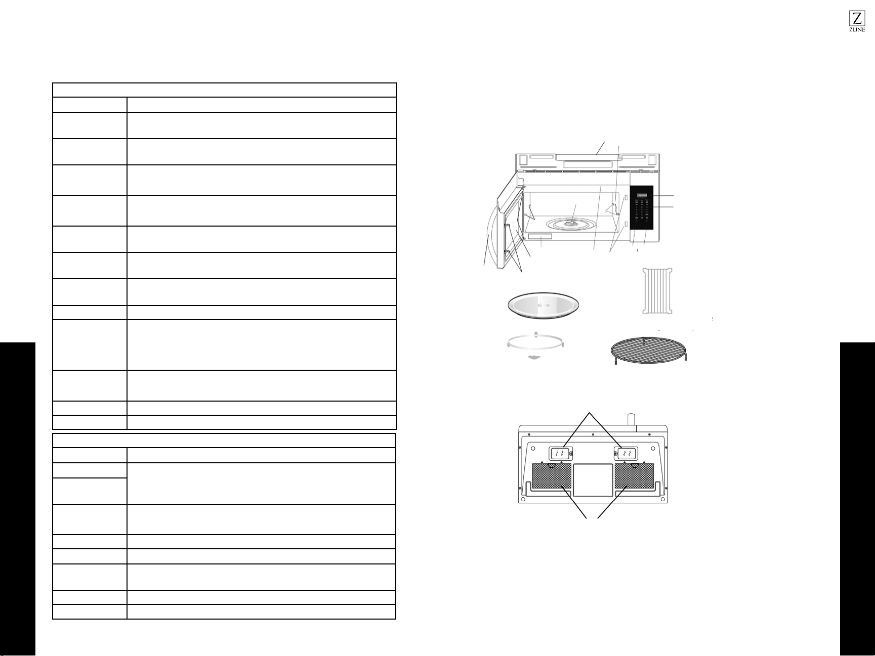
2827
Accessories
Materials in Microwave
OPERATION
MATERIALS YOU CAN USE IN MICROWAVE OVEN
Utensils Remarks
Browning dish
Follow manufacturer* instructions. The bottom of browning dish must be at least
3/16 inch above the turntable. Incorrect usage may cause the turntable to break.
Dinnerware
Microwave-safe only. Follow manufacturer’s instructions. Do not use
cracked or chipped dishes.
Glass jars
Always remove lid. Use only to heat food until just warm. Most glass jars are not
heat resistant and may break.
Glassware
Heat-resistant oven glassware only. Make sure there is no metallic trim. Do not use
cracked or chipped dishes.
Oven cooking bags
Follow manufacturer* instructions. Do not close with metal tie. Make slits to allow
steam to escape.
Paper plates
and cups
Use for short term cooking/warming only. Do not leave oven unattended while
cooking.
Paper towels
Use to cover food for reheating and absorbing fat. Use with supervision for a short-
term cooking only.
Parchment paper Use as a cover to prevent splattering or a wrap for steaming.
Plastic
Microwave-safe only. Follow the manufacturer* instructions. Should be labeled
“Microwave Safe”. Some plastic containers soften, as the food inside gets hot.
“Boiling bags” and tightly closed plastic bags should be slit, pierced or vented as
directed by package. Microwave-safe only. Use to cover food during cooking
Plastic wrap
Microwave-safe only. Use to cover food during cooking to retain moisture. Do not
allow plastic wrap to touch food.
Thermometers Microwave-safe only (meat and candy thermometers).
Wax paper Use as a cover to prevent splattering and retain moisture.
MATERIALS TO BE AVOIDED IN MICROWAVE OVEN
Utensils Remarks
Aluminum tray
May cause arcing. Transfer food into microwave-safe dish.
Food carton with
metal handle
Metal or metal-
trimmed utensils
Metal shields the food from microwave energy. Metal trim may cause arcing.
Metal twist ties May cause arcing and could cause a fire in the oven.
Paper bags May cause a fire in the oven.
Plastic foam
Plastic foam may melt or contaminate the liquid inside when exposed to high
temperature.
Wood Wood will dry out when used in the microwave oven and may split or crack.
Parchment paper Use as a cover to prevent splattering or a wrap for steaming.
OPERATION
1. Microwave Oven Door
2. Door Hinges
3. Waveguide Cover (DO
NOT REMOVE)
4. Turntable motor shaft
5. Microwave oven light
6. Rack holders
7. Safety door latches
8. Handle
9. Light Button
10. Vent button
11 . Control Panel
12. Display Panel
13. Ventilation
14. Menu label
15. Removable Turntable Plate
16. Removable Turntable
Support
17. Rack for 2-level cooking/
reheating
18. Light cover/Filter Access
Door
19. Grease Filters
BACK
FRONT
18
19
BOTTOM
1
14
7
16
17
15
8
2
4
6
6
75
10
11
12
3
13
9
Do not leave rack in microwave unless cooking on rack
FRONT
Remove the oven and all materials from the carton and oven cavity. Your oven comes
with the following accessories:
USING VENT FAN
The pad controls the 2-speed vent fan. If the vent fan is OFF, the first touch of the vent
pad will turn the fan from HIGH > LOW > OFF
USING COOKTOP LIGHT
The pad controls the cooktop light. If the light is OFF, the first touch of the light pad will
turn the light from HIGH > LOW > OFF
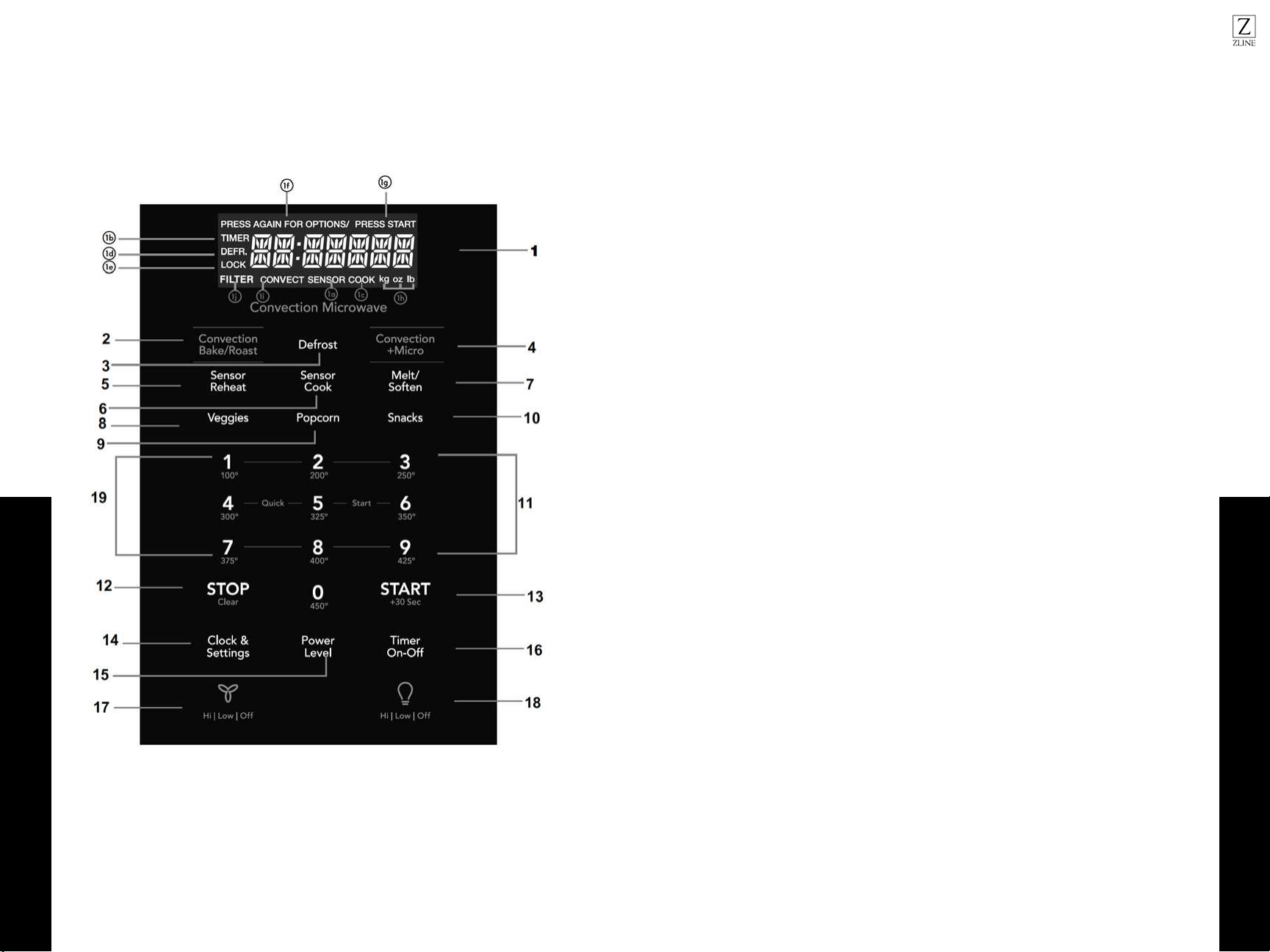
3029
Keys
Keys
OPERATION
OPERATION
1. Display - features as a clock and indicator that show time, cooking time settings,
cook power, sensor, quantities, weights, and cooking functions
1a. SENSOR - when using sensor cook
1b. TIMER - when timer is being set or running
1c. COOK - starting microwave cooking
1d. DEFR - defrosting food
1e. LOCK - control lock
1f. PRESS AGAIN FOR OPTIONS - additional options are available
1g. PRESS START - before a valid function
1h. KG, OZ, LB - when choosing weight
1i. CONVECT - when choosing convect
1j. FILTER - replace filter
2. Convection Bake/Roast
3. Defrost
4. Convection + Micro
5. Sensor Reheat (4 settings)
6. Sensor Cook
7. Melt/Soften
8. Veggies
9. Popcorn
10. Snacks
11 . Numerical Pads
12. Stop/Clear
13. Start (+30 seconds)
14. Clock & Settings
15. Power Level (11 power levels)
16. Timer (On-Off)
17. Exhaust (High/Low/Off) - use to turn the exhaust fan off, or to adjust speed
18. Surface Light - press to activate and adjust brightness of lights
19. Quick start (9 instant key settings)
3231
One Touch Cooking
One Touch Cooking
OPERATION
ONE TOUCH COOKING
POPCORN
The microwave oven lets you pop 3.3, 3.0, 1.75 oz bags of commercially packaged
microwave popcorn. Pop only one package at a time. If you are using a microwave
popcorn popper, follow manufacturer’s instructions.
Touch POPCORN.
1. Press again for options
2. Press START
VEGETABLES
The microwave can cook potatoes, frozen vegetables, and fresh vegetables.
1. Touch VEGGIES
2. Press again for options
3. Press START
FOOD AMOUNT PROCEDURE
Potato
1-4
pieces
Cooking times are based on an average 8 oz. potato. Pierce
with forks in several places. Place on paper towel on turntable.
Press the VEGGIES pad one time for potato. After cooking,
remove from oven and let stand for 5 minutes
Fresh Vegetables
Broccoli
Brussels Sprouts
Cabbage
Cauliflower
Spinach
Zucchini
2 cups
Wash and place in casserole. Don’t add water if the vegetables
have been washed. Cover with lid for tender vegetables. Use
plastic wrap for tender-crisp vegetables. Press VEGGIES twice.
After cooking, stir. Let stand for 2-5 mins.
Fresh Vegetables
Carrots
Corn on cob
Green beans
Winter Squash
Place in casserole. Add 1-4 tbsp. water. Cover with lid for
tender vegetables. Use plastic wrap cover for tender crisp
vegetables. Press VEGGIES twice for fresh vegetables. After
cooking, stir, if possible. Let stand, covered, for 2-5 minutes.
Frozen Vegetables Don’t add water if the vegetables have been washed. Press
VEGGIES three times. After cooking, stir and let stand, covered,
for 3 mins.
OPERATION
ONE TOUCH COOKING
SNACK
Snack Menu is for cooking/heating foods for a short amount of time.
1. Touch SNACKS
2. Press again to cycle through the menu.
• CHOCOLATE CHIP COOKIES
• FROZEN MW PIZZA
• HOT DOGS
• FROZEN KID’S MEAL
• MEAL IN A CUP
• SOUP
3. Press START
4. Press the numerical pad to choose the portions.
5. Press START
MELT/SOFTEN
The oven uses lower power to melt and soften items
1. Touch MELT/SOFTEN.
2. Press again to cycle through the menu:
• BUTTER
• CHOCOLATE
• ICE CREAM
• CREAM CHEESE
3. Press START
4. Press the number keys to set the weight.
5. Press START

3433
Cookware Tips
Convection Cooking
OPERATION
CONVECTION COOKING
There are ten temperatures of convection:
1. 100F
2. 200F
3. 250F
4. 300F
5. 325F
6. 350F
7. 375F
8. 400F
9. 425F
10. 450F
Convection cooking uses a heating element to raise the temperature of the air
inside the oven. Any oven temperature from 100F to 450F may be set. A fan gently
circulates this heated air throughout the oven, over and around the food.
Because the heated air is kept constantly moving, not permitting a layer of cooler air
to develop around the food, some foods cook faster than in regular oven cooking.
For best results, always use the round wire rack when convecting cooking. Reduce
package/recipe temperature 25F for baked goods. The round wire rack is required
for good air circulation and even browning.
USING CONVECTION WITH PREHEATING
1. Press Convection Bake/Roast once (PREHEAT ENTER TEMP)
2. Press the number on the keypad on the desired temperature (see below number.
ex: 375F, press 7...)
3. Press START and the oven will PREHEAT
4. Temperature will show on the display, once it’s done preheating. Open the door
when it’s done.
5. Place the food in the oven and press the number keys to set the cooking time.
6. Press START
OPERATION
USING CONVECTION WITHOUT PREHEATING
1. Press Convection Bake/Roast twice (BAKE ROAST ENTER TEMP)
2. Press the number on the keypad on the desired temperature (see below number.
ex: 375F, press 7...)
3. Press START
4. Place the food in the oven and press the number keys to set the cooking time.
5. Press START
MICROWAVE + CONVECTION COMBINATION
1. Press Convection + Micro (BAKE 325 °F)
2. Press START
3. Place the food in the oven and press the number keys to set the cooking time.
4. Press START
COOKWARE TIPS
• Use the round wire rack during convection baking.
• Avoid opening the oven door during cooking - each time the door is opened, the
oven loses heat and this will cause uneven baking.
• Metal pans are recommended for all types of baked products, but especially
where browning or crusting is important.
• Dark or dull finish metal pans are best for bread and pies because they absorb
heat and produce crisper crust.
• Shiny aluminum pans are best for cakes, cookies, or muffins.
• Glass/glass ceramic casserole or baking dishes are best suited for egg and
cheese recipes.
• For combination cooking, use glass or glass ceramic containers. Be sure not to
use items with metal trim as it may cause arcing (sparking) with oven wall or
oven shelf, damaging the cookware, the shelf, or the oven.

3635
Sensor Cooking
Sensor Cooking
OPERATION
SENSOR COOKING
Sensor cooking has an electronic controlled sensor that detects the vapor (moisture
and humidity) emitted from the food as it heats. The sensor adjusts the cooking times
and power level for various foods and quantities automatically.
BEFORE USING SENSOR COOKING
1. Be sure the exterior of the cooking container and the interior of the oven are dry.
Wipe off any moisture with a dry cloth or paper towel.
2. The oven works with foods at normal storage temperature. For example, popcorn
would be at room temperature.
3. More or less food than the quantity listed in the chart should be cooked
following the guidelines in any microwave cookbook.
4. During the first part of SENSOR COOKING, food name will appear in the
display. Do not open the oven door or press the STOP/CLEAR pad during
this part of the cycle as it will interrupt the process. When the sensor detects
the vapor emitted from the food, remainder of cooking time will appear. Door
maybe opened when remaining cooking time appears in the display. Stir or
season food as desired.
5. If the sensor does not detect vapor properly when popping popcorn, the oven
will turn off and the correct time of day will display. It will also show an ERROR
CODE and the oven will turn off.
6. Check food for temperature after cooking. If additional time is needed, continue
to cook manually
COVERING FOODS
Some cooks cook better when covered. Use
1. Casserole lid
2. Plastic wrap
3. Wax Paper
Be careful when removing any covering to allow steam to escape away from you.
OPERATION
SENSOR COOK MENU
1. Touch SENSOR COOK.
2. Press again to cycle through the menu:
• Bacon
• Frozen Dinner
• Rice
• Frozen Breakfast
• Frozen Pizza
3. Press START
USING SENSOR REHEAT
1. Touch SENSOR REHEAT
2. Press again to cycle through the menu:
• Beverage
• Pizza
• Soup Sauce
• Casserole
3. Press START

3837
Operating Tips
Defrost
OPERATION
OPERATION
AUTO DEFROST
The auto defrost feature provides with the best defrosting method for frozen foods. The
cooking guide will show you which defrost sequence is recommended for the food you
are defrosting.
USING AUTO DEFROST
1. Touch AUTO DEFROST
2. Press again to cycle through the menu:
• Meat
• Poultry
• Fish
3. Press START
4. Press the number keys to set the weight
5. Press START
For added convenience, the AUTO DEFROST includes a built-in beep mechanism that
reminds you to check, turn over, separate, or rearrange the food in order to get the best
defrost results. Three different defrosting levels are provided: (available is 0.1-6 lbs)
1. MEAT
2. POULTRY
3. FISH
MANUAL DEFROST
You can defrost any frozen food, either raw or previously cooked, by using power
level for 30%. For either raw or previously cooked frozen food, the rule of thumb is
approximately 4 minutes per pound. For example, defrost 4 minutes for 1 pound of
frozen spaghetti sauce.
Always stop the oven periodically to remove or separate the portions that are
defrosted. If food is not defrosted at the end of the estimated defrosting time, program
the oven in 1 minute increments on power level 30% until totally defrosted. When using
plastic containers from the freezer, defrost only long enough to remove from the plastic
in order to place in a microwave-safe dish.
OPERATING TIPS
• For best results, remove fish, shell fish, meat and poultry from its original closed
paper or plastic package (wrapper). Otherwise, the wrap will hold steam and juice
close to the food, which can cause the outer surface of the food to cook. Open
containers, such as cartons, before placing in the oven.
• For best results, roll your ground meat into a ball before freezing. During the
DEFROST cycle, the microwave will signal when its time to turn the meat over. Scrape
off any excess frost from the meat and continue defrosting.
• Place food in a shallow container or on a microwave roasting rack to catch the drips.
• The weight to enter is the net weight in pounds and tenths of pounds (the weight of
the food minus the container).
• Before starting, make sure to remove any and all metal twist-ties that often come with
frozen food bags, and replace with strings or elastic bands.
• Always slit or pierce plastic pouches/packaging.
• Bend plastic pouches of food to ensure even defrosting.
• Always underestimate defrosting time. If defrosted food is still icy in the center, return
it to the microwave oven for more defrosting. The length of defrosting time varies
according to how solidly the food is frozen.
• The shape of the package affects how quickly food will defrost. Shallow packages
will defrost more quickly than a deep block.
• As food begins to defrost, separate the pieces. Separated pieces defrost more easily.
• Use small pieces of aluminum foil to shield parts of food, such as chicken wings, leg
tips, fish tails, or areas that start to get warm. Make sure that the foil does not touch
the sides, top, bottom of the oven. The foil can damage the oven lining.
• For better results, let food stand after defrosting.
• Turn over food during defrosting or standing time. Break apart and remove food as
required.
• The rack allows several foods to be cooked or reheated at one time. However, for
the best cooking and reheating, use Turntable ON function and cook with SENSOR
COOKING or AUTO COOKING without the rack. When the rack is used, set time
and power level manually. Allow plenty of space around and between the dishes.
Pay close attention to the cooking and reheating progress. Reposition the foods and
reverse them from the rack to turntable and/or stir them at least once during any
cooking or reheating time. After cooking or reheating, stir if possible. Using a lower
power level will assist in better cooking and reheating uniformity.
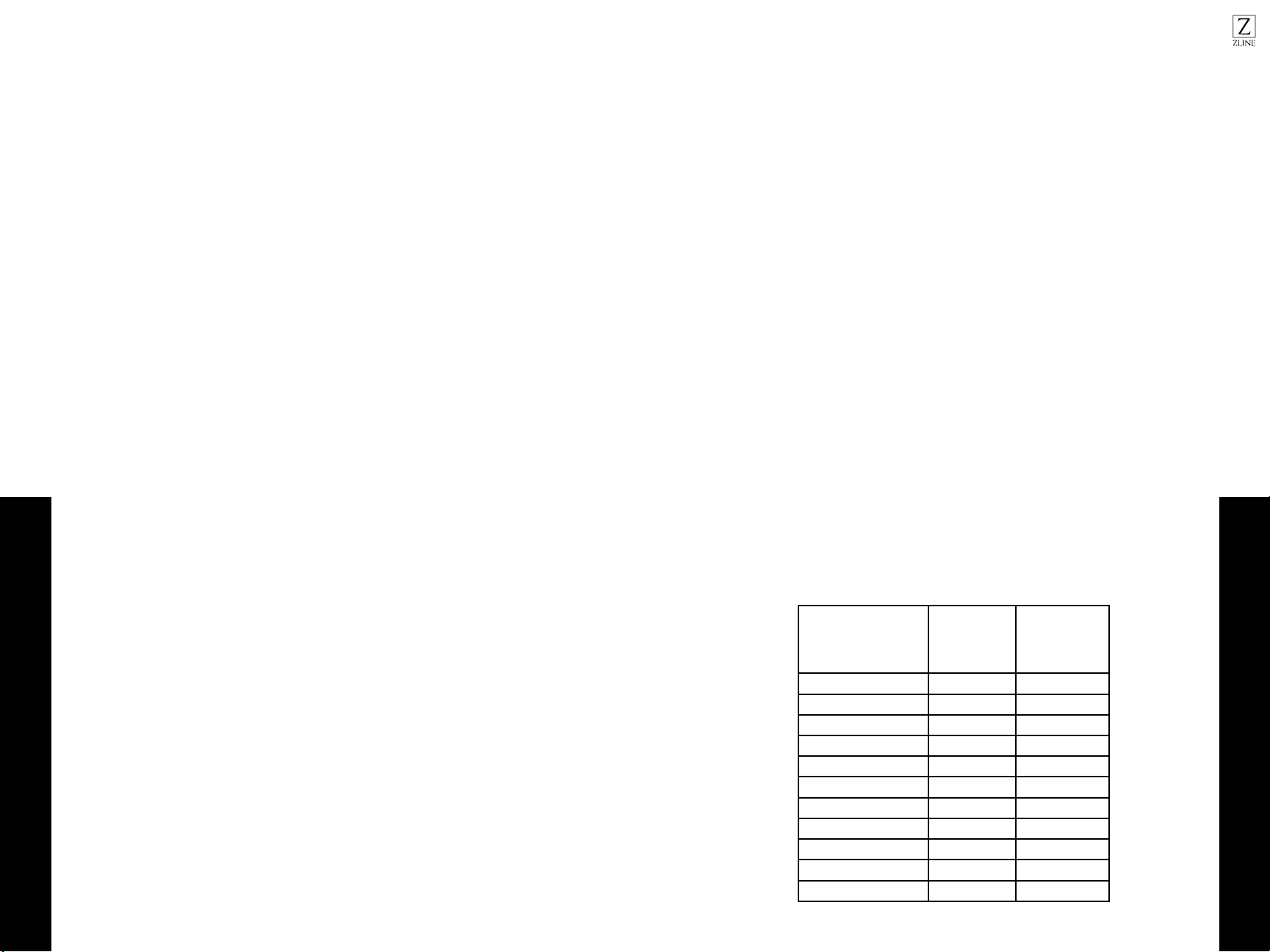
4039
Timed Cooking
Clock
OPERATION
CLOCK & SETTINGS
The microwave oven has settings that allow you to customize the operation for your
convenience. Below are functions showing the various settings. Touch the CLOCK &
SETTINGS to cycle through the menu.
1. Clock
2. Control Lock
3. Power Save
4. Volume: Low/Medium/High/Off
5. Pure Air Filter Reset/Off
6. Language
7. Weight LB/KG
8. Demo
SETTING THE CLOCK
The clock can be disabled when the microwave is first plugged in and the STOP/
CLEAR is selected. To re-enable the clock:
1. Press CLOCK & SETTINGS
2. Enter the time using the number pad
3. Press START
TIME COOKING
1. Press the number on the keypad for the desired time (ex: 5 minutes and 30
seconds, press 5 3 0)
2. Press START
INTERRUPTING COOKING
You can stop the oven during a cycle by opening the door. The oven stops heating
and the fan turns off, but the light stays on.
1. To restart cooking, close the door and Touch START
2. If you do not want to continue cooking, open the door and touch STOP
OPERATION
USING ONE TOUCH START
This is a time saving pad that will automatically start cooking 2 seconds after
selected. Numeric key
1, 2, 3......or 9 can be touched for a 1 minute, 2 minutes or 9 minutes automatic start
cooking feature.
1. Press the number on the keypad for the desired time (ex: 2 minutes, press 2)
2. Press START
Note: “Food” will be displayed if a quick start cooking cycle or +30 sec key is not
selected within 5 minutes of placing food in the microwave. You must open then close
the door again to clear ‘’Food” from the display.
SETTING TIMED COOKING WITH POWER LEVEL
This feature lets you program a specific cook time and power. For best results, there
are 11 power level settings in addition to HIGH (100%) power.
1. Press the number on the keypad for the desired time (ex: 5 minutes and 30
seconds, press 5 3 0)
2. Press POWER LEVEL
3. Press START
PRESS POWER LEVEL
PAD NUMBER OF TIMES
FOR DESIRED POWER
APPROXIMATE
PERCENTAGE
OF POWER
COMMON
WORDS FOR
POWER LEVELS
Power Level x 1 100% High
Power Level x 2 90%
Power Level x 3 80%
Power Level x 4 70% Medium High
Power Level x 5 60%
Power Level x 6 50%
Power Level x 7 40%
Power Level x 8 30% Med Low/Defrost
Power Level x 9 20%
Power Level x 10 10% Low
Power Level x 11 0%

4241
Settings
Settings
OPERATION
SETTING TWOSTAGE COOKING
For best results, some recipes call for different power levels during a cook cycle .
You can program your oven for two power level stages during the cooking cycle.
Suppose you want to set a 2-stage cook cycle. The first stage is a 3 minute cook time
at 80% cook power then a 7 minute cook time at 50% cook power.
1. Press the numbers on the keypad to set cook time for the first stage. (ex: 3
minutes, press 3 0 0)
2. Press POWER LEVEL three times
3. Press the numbers on the keypad to set cook time for the second stage. (ex: 7
minutes, press 7 0 0)
4. Press POWER LEVEL six times
5. Press START
SETTING CONTROL LOCK
1. Press CLOCK & SETTINGS two times to get to CONTROL LOCK
2. Press START
3. To turn off, touch the CLOCK & SETTINGS and touch START
SETTING POWER SAVE ON/OFF
1. Press CLOCK & SETTINGS three times to get to POWER SAVE OFF
2. Press START to toggle between ON & OFF
TURNING SOUND LOW/MED/HIGH/OFF
Audible signals are available to guide you when setting and using your oven.
• A programming tone will sound each time you touch a pad
• Three tones signal the end of a kitchen timer countdown
• Three tones signal the end of a cooking cycle
1. To adjust, press CLOCK & SETTINGS four times to get to VOLUME ON
2. Keep pressing to cycle through the options: ON, OFF, LOW, MED, HIGH
3. To set, press START
OPERATION
SETTING FILTER RESET/FILTER OFF
Select FILTER RESET to turn off “FILTER” icon and reset to remind in 6 months; if you
want to turn off “FILTER” icon notification and not remind at all, select FILTER OFF and
press START
1. Press CLOCK & SETTINGS and cycle through until you get to FILTER RESET
2. Press START to toggle between FILTER RESET/OFF
SETTING LANGUAGE
There are two languages available: ENGLISH and FRENCH
1. Press CLOCK & SETTINGS and cycle through until you get to FRENCH
2. Press START to toggle between ENGLISH and FRANCAIS
SETTING WEIGHT TO LB/KG
There are two weight units available: LB/KG
1. Press CLOCK & SETTINGS and cycle through until you get to LB/KG
2. Press START to toggle between KG to LB
SETTING DEMO MODE ON/OFF
When DEMO mode is on, programming functions will work in a rapid countdown
mode with no cooking power
1. Press CLOCK & SETTINGS and cycle through until you get to DEMO OFF
2. Press START to toggle between ON and OFF
SETTING KITCHEN TIMER
The microwave oven can be used as a kitchen timer. Set up from 99 minutes to 99
seconds. The kitchen timer can be used while the microwave oven is running.
• The timer will not stop if the door is open. To cancel the timer, press TIMER ON-
OFF
1. Press TIMER ON-OFF
2. Use the number keypad for the time to count down to
3. Press TIMER ON-OFF to start counting down
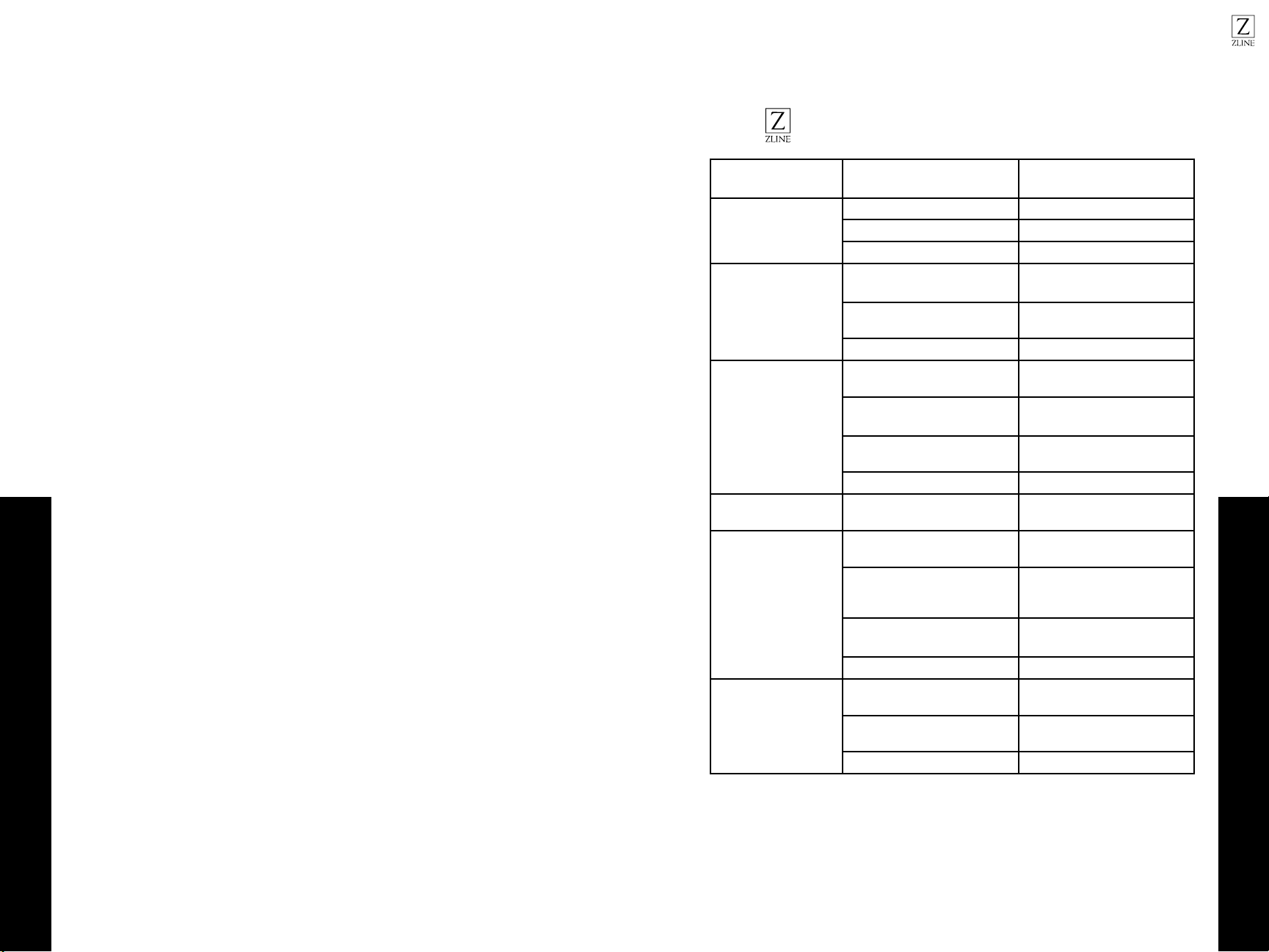
4443
Vent Fan & Cooktop Light
Troubleshooting
OPERATION
USING VENT FAN
The pad controls the 2-speed vent fan. The vent fan will go from HIGH, LOW, OFF.
1. Press the VENT icon
2. To turn off, cycle through the options until the fan is off.
If the temperature from the range or cooktop below the oven gets too hot, the vent fan
will automatically turn on to protect the oven. It may stay on up to an hour to cool the
oven. When this occurs, the vent pad will not turn the fan off.
USING COOKTOP LIGHT
The pad controls the 3-setting cooktop light. The vent fan will go from HIGH, LOW,
OFF.
1. Press the LIGHT icon
2. To turn off, cycle through the options until the fan is off.
TROUBLESHOOTING
FAULT POSSIBLE CAUSE TROUBLESHOOTING
Oven won’t start
Electrical cord is unplugged. Plug into the outlet.
Door is open. Close the door and retry.
Wrong operation is set. Check instructions.
Arcing or sparking
Materials to be avoided in
microwave oven were used.
Use microwave-safe cookware
only.
The oven is operated when
empty.
Do not operate with oven
empty.
Spilled food remains in cavity. Clean cavity with wet towel.
Unevenly cooked food
Materials to be avoided in
microwave oven were used.
Use microwave-safe cookware
only.
Food is not defrosted
completely.
Completely defrost food.
Cooking time, power level is not
suitable.
Use correct cooking time,
power level.
Food is not turned or stirred. Turn or stir food.
Overcooked foods
Cooking time and/or power
level is not suitable.
Use correct cooking time and/
or power level.
Undercooked foods
Materials to be avoided in
microwave were used.
Use correct cooking time and/
or power level.
Oven ventilation ports are
restricted.
Check to see that oven
ventilation ports are not
restricted.
Cooking time and/or power
level is not suitable.
Use correct cooking time and/
or power level.
Food is not turned or stirred. Turn or stir food.
Improper Defrosting
Materials to be avoided in
microwave were used.
Use microwave-safe cookware
only.
Cooking time, power level is not
suitable.
Use correct cooking time,
power level.
Food is not turned or stirred. Turn or stir food.
ZLINE Customer Service is available at 1-614-777-5004.