Loading ...
Loading ...
Loading ...
13www.petsafe.net
EN
FR
ES
NL
IT
DE
Run Through Prevention
This system includes a unique “run-through” prevention so that your dog cannot escape the Pet Area without receiving an
increased level of Static Stimulation. The Receiver Collar automatically increases the Static Stimulation when your dog continues
more than 20% of the way through the pet fencing Boundary Width. For example, if the signal is detected 3 metres from
the wire and your dog enters the Static Stimulation Zone, this feature is activated when he is approximately 2.4 metres from
the Boundary Wire. Your dog will then receive a Static Stimulation that is at an increased level corresponding to the Static
Stimulation level setting on the Receiver Collar. The Receiver Collar is equipped to automatically increase the level of Static
Stimulation the longer your pet remains in the Static Stimulation Zone if the collar is set at level 2 or above.
Over Stimulation Protection
In the unlikely event that your pet “freezes” in the Static Stimulation Zone, this feature limits the Static Stimulation duration to a
maximum of 30 seconds. While the system locks out further Static Stimulation, the warning tone will continue until the pet leaves
the Static Stimulation Zone.
Function and Response Table
Note: Begin training with Static Stimulation Level 2 and only increase if your pet does not respond to the Static Stimulation.
Indicator Light
Response
Static Stimulation
Level
Receiver Collar Function Temperament of Pet
1 Red Flash 1 No Static Stimulation, Tone Only
2 Red Flashes 2 Low Static Stimulation Timid
3 Red Flashes 3 Medium Static Stimulation Timid or Average
4 Red Flashes 4 Medium High Static Stimulation Average or High Energy
5 Red Flashes 5 High Static Stimulation High Energy
Flashes 1 Red Flash every
20 seconds
Low Battery
STEP 6
Set the Boundary Width and Test the
Receiver Collar
With the Boundary Wire in place and properly connected, it is time to set the containment eld and
test the system.
The Receiver Collar should NOT be on your dog when
the system is tested.
Note: The Receiver Collar is waterproof, which can make the tone hard to hear.
The ashing Test Light when held to the Contact Points indicates the Receiver Collar is delivering
Static Stimulation.
To best utilize the automatic Run-Through Prevention feature, the containment Boundary Width should
extend at least 1.8 m to 3 m (6 ft to 10 ft) on each side of the Boundary Wire (total Boundary Width of 3.7 m to 6 m (12 ft to 20 ft).
1. Apply Power to the Fence Transmitter with the supplied Power Adapter.
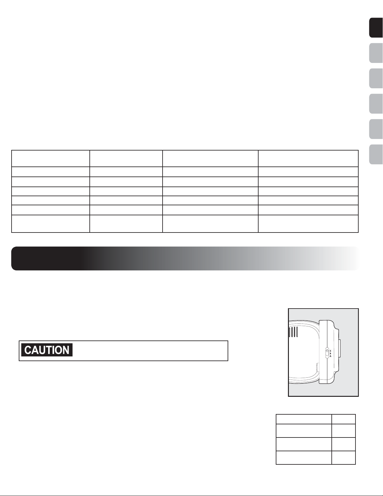
2. Set the Boundary Width Control Switch (located on the side of the Fence Transmitter) (6A)
to the A, B, or C setting based on the total length of Boundary Wire used. Setting B is used
for most properties. The following table will indicate the proper setting.
3. The width of the containment eld is adjusted using the transmitter’s Boundary Width
Control knob. Turn the knob counter clockwise until the alarm sounds and the Loop Indicator
Light is no longer lit. Turn the knob clockwise and increase by 2 numbers. The alarm
should turn OFF and the light should turn ON.
6A
Amount of Wire Setting
Greater than 731 m
(2400 feet)
A
Up to 396 m
(1300 feet)
B
396 m to 731 m
(1300 feet to 2400 feet)
C
Loading ...
Loading ...
Loading ...