Loading ...
Loading ...
Loading ...
Operation
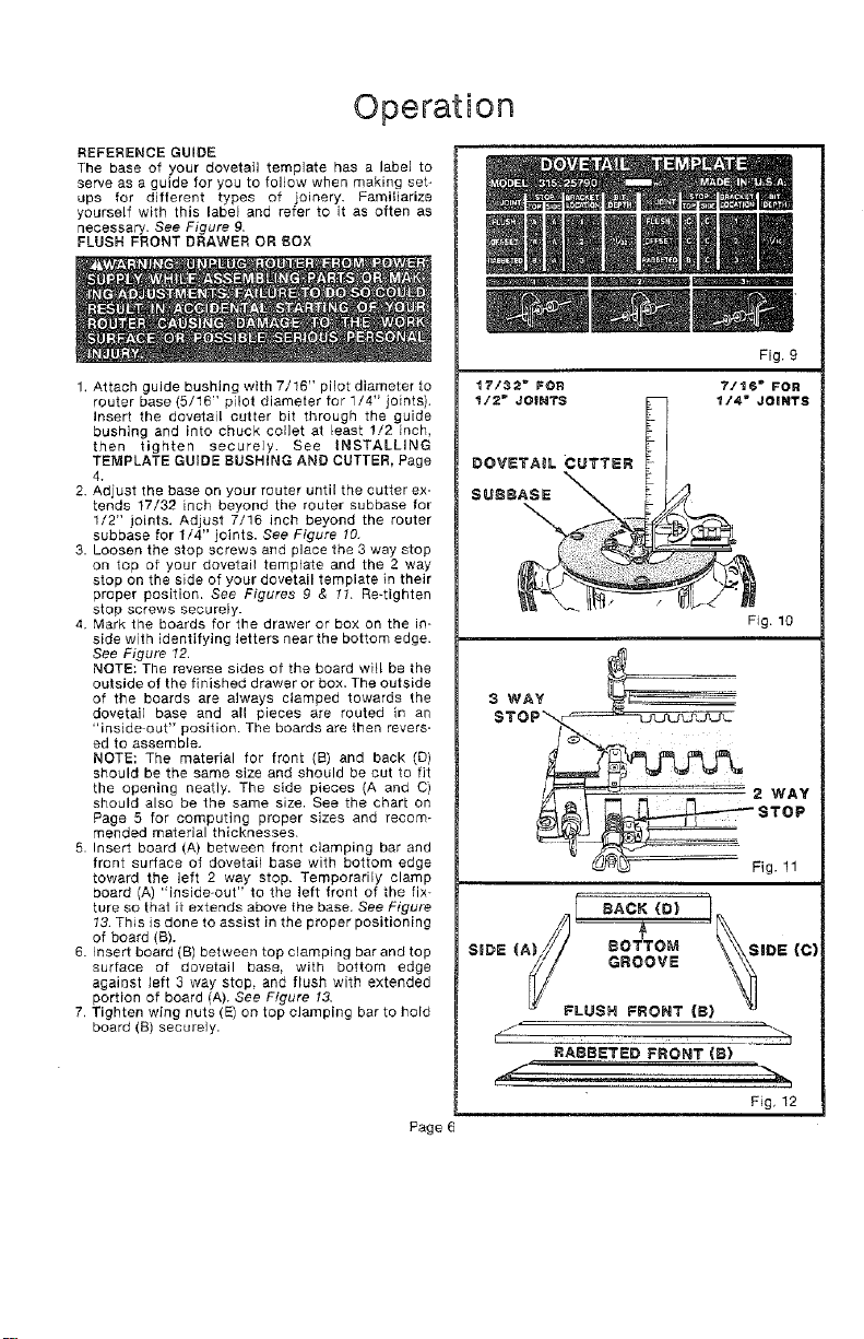
REFERENCE GUIDE
The base of your dovetail template has a label to
sewe as a guide for you to follow when making set_
ups for different types of joinery. Familiarize
yourself with this label end refer to it as often as
necessary. See Figure g,
FLUSH FRONT DRAWER OR BOX
1. Attach guide bushing with 7/16" pilot diameter to
router base {5/16" pilot diameter for 1/4" joints).
Insert the dovetail cutter bit through the guide
bushing and into chuck collet at least !/2 inch,
then tighten securely. See INSTALLING
TEMPLATE GUIDE BUSHING AND CUTTER, Page
4.
2. Adjust the base on your router until the cutter ex-
tends 17/32 inch beyond the router subbase for
1/2" joints. Adjust 7/16 inch beyond the router
subbase for 1/4" joints. See Figure 10.
3. Loosen the stop screws and place the 3 way stop
on top af your dovetail template and the 2 way
stop on the side of your dovetail template in their
proper position. See Figures 9 & 11. Re-tighten
stop screws securely.
4. Mark the boards for the drawer or box on the in-
side with identifying letters near the bottom edge.
See Figure 12.
NOTE: The reverse sides of the board will be the
outside of the finished drawer or box. The outside
of the boards are always clamped towards the
dovetail base and all pieces are routed in an
"inside out" position. The boards are then revers-
ed to assemble.
NOTE: The material for front (B) and back (D)
should be the same size and should be cut to fit
the opening neatly. The side pieces (A and C)
should also be the same size. See the chart on
Page 5 for computing proper sizes and recom-
mended material thicknesses.
5. Insert board (A) between front clamping bar and
front surface of dovetail base with bottom edge
toward the left 2 way stop. Temporarily clamp
board (A) "inside-out" to the left front of the fix-
ture so that it extends above the base. See Figure
13. This is done to assist in the proper positioning
of board (B).
6. Insert board (B) between top clamping bar and top
surface of dovetail base, with bottom edge
against left 3 way stop, and flush with extended
portion of board (A). See Figure 13.
7. Tighten wing nuts (E) on top clamping bar to hold
board (B) securely.
Page
Fig. 9
17/32 _ FOR 7/t6 _ FOR
1/2" JOINTS _ _/4" JOINTS
DOVETAIL CUTTER
SUSS
Fig. 10
S WAY
Fig. 11
sAcK r
(A)/, BOTTOM
SiDE V/ SiDE (C)
y GROOVE
LUSH FRONT (8}
j ' "_,
RABBETED FRONT (S)
Fig, 12
Loading ...
Loading ...
Loading ...