Loading ...
Loading ...
Loading ...
OPERATION
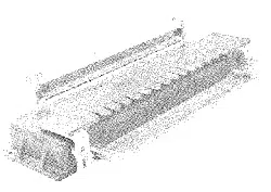
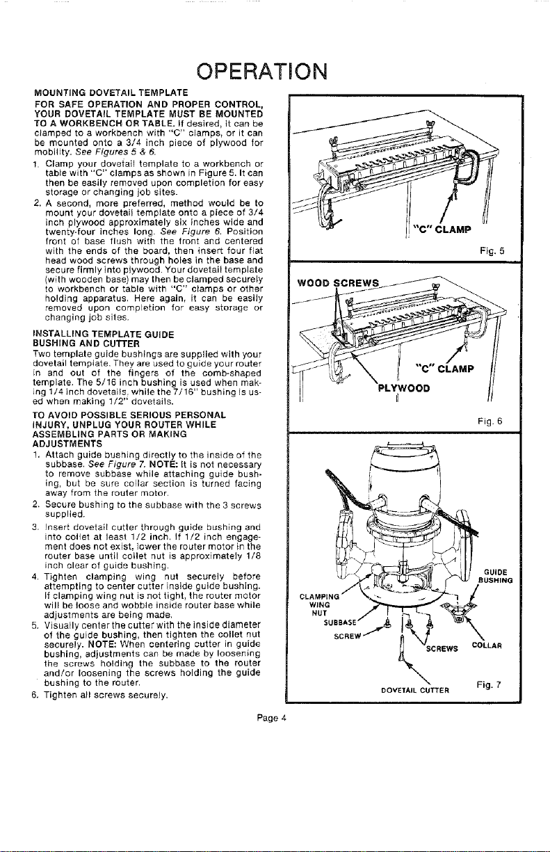
MOUNTING DOVETAIL TEMPLATE
FOR SAFE OPERATION AND PROPER CONTROL,
YOUR DOVETAIL TEMPLATE MUST BE MOUNTED
TO A WORKBENCH OR TABLE. If desired, it can be
clamped to a workbench with "C" clamps, or it can
be mounted onto a 3/4 inch piece of plywood for
mobility. See Figures 5 & 6.
1. Clamp your dovetail template to a workbench or
tab}e with "C" clamps as shown in Figure 5. It can
then be easily removed upon completion for easy
storage or changing job sites.
2. A second, more preferred, method would be to
mount your dovetai_ template onto a piece of 3/4
inch plywood approximately six inches wide and
twenty-four inches long. See Figure 6. Position
front of base flush with the front and centered
with the ends of the board, then insert four fiat
head wood screws through holes in the base and
secure firmly into plywood. Your dovetail template
(with wooden base) may then be clamped securely
to workbench or table with "C" clamps or other
holding apparatus. Here again, it can be easily
removed upon completion for easy storage or
changing job sites.
INSTALLING TEMPLATE GUIDE
RUSHING AND CUTTER
Two template guide bushings are supplied with your
dovetail template. They are used to guide your router
in and out of the fingers of the comb-shaped
template. The 5/16 inch bushing is used when mak-
ing 1/4 inch dovetails, while the 7/16" bushing is us-
ed when making 1/2" dovetails.
1"O AVOID POSSIBLE SERIOUS PERSONAL
INJURY, UNPLUG YOUR ROUTER WHILE
ASSEMBLING PARTS OR MAKING
ADJUSTMENTS
1. Attach guide bushing directly to the inside of the
subbase, See Figure 7. NOTE: It is not necessary
to remove subbase while attaching guide bush-
ing, but be sure collar section is turned facing
away from the router motor.
2. Secure bushing to the subbase with the 3 screws
supplied.
3. Insert dovetail cutter through guide bushing and
into collet at least 1/2 inch, If 1/2 inch engage-
ment does not exist, lower the router motor in the
router base until collet nut is approximately 1/8
inch clear of guide bushing.
4. Tighten clamping wing nut securely before
attempting to center cutter inside guide bushing.
If clamping wing nut is not tighL the router motor
will be loose and wobble inside router base while
adjustments are being made.
5. Visually center the cutter with the inside diameter
of the guide bushing, then tighten the collet nut
securely. NOTE: When centering cutter in guide
bushing, adjustments can be made by loosening
the screws holding the subbase to the router
and!or loosening the screws holding the guide
bushing to the router.
6, Tighten all screws securely.
Fig. 5
WOOD SCREWS
"C" CLAMP
PLYWOOD
r_
Fig. 6
SCREWS COLLAR
DOVEfAIL CUTTER Fig. 7
Page 4
Loading ...
Loading ...
Loading ...