OWNERS
MANUAL
MODEL NO.
315.25790
CAUTION:
Read Rules for
Safe Operation
and Instructions
Carefully
SAVE THIS
MANUAL FOR
FUTURE REFERENCE
i:_:i!:ii:i_i_iiiiil
_ __....._i! ¸ .......
:!
..... _,_
i
}
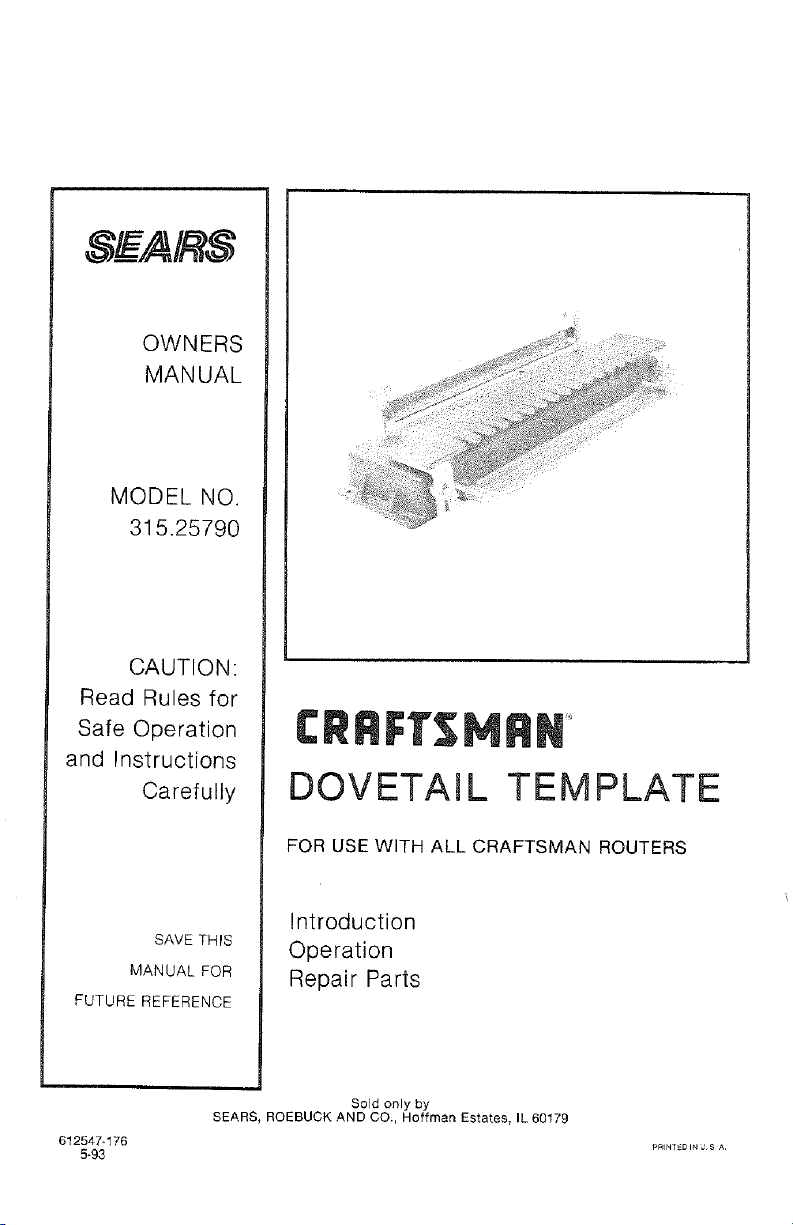
TEMPLATE
FOR USE WITH ALL CRAFTSMAN ROUTERS
Introduction
Operation
Repair Parts
Sold only by
SEARS, ROEBUCK AND CO., Hoffman Estates, IL 60179
612647-176 Pa_NT_DI._SA
5"93
RULES FOR SAFE OPERATION
2.
3.
4.
5.
6.
7.
8.
9.
10.
11.
12.
13.
14.
15.
16.
17.
18,
DaSCONNECT TOOLS. When not in use, before assembling, before servicing, or
when changing attachments, blades, bits, cutters, etc,, all tools shoutd be discon-
nected.
BE SURE ALL ADJUSTMENTS ARE PROPERLY SET AND SECURELY FASTENED.
KEEP GUARDS IN PLACE and in working order.
KEEP WORK AREA CLEAN. Cluttered areas and benches invite accidents.
AVOID DANGEROUS ENVIRONMENT. Don't use power tool in damp or wet Iooa-
tions or expose to rain. Keep work area we!l tit.
KEEP CHILDREN AWAY. Atl visitors should wear safety glasses and be kept a safe
distance from work area. Do not let visitors contact tool or extension cord.
STORE iDLE TOOLS. When not in use, tools should be stored in a dry, high or
locked-up place -- out of the reach of children.
WEAR PROPER APPAREL, No loose clothing or jewelry to get caught in moving
parts. Rubber gloves and footwear are recommended when working outdoors, Also,
wear protective hair covering to contain long hair.
USE SAFETY GLASSES with all tools, Also face or dust mask if operation is dusty.
SECURE WORK. Use clamps or a vise to hold work, It's safer than using your hand
and it frees both hands to operate tool.
DON'T OVERREACH. Keep proper footing and balance at all times. Do not use on a
ladder or unstable support.
NEVER USE iN AN EXPLOS0VE ATMOSPHERE. Normal sparking of the motor could
ignite fumes.
KEEP TEMPLATE DRY, CLEAN, AND FREE FROM OIL AND GREASE,
STAY ALERT, Watch what you are doing and use common sense. Do not operate
tool when you are tired, Do not rush.
DRUGS, ALCOHOL, MEDICATION. Do not operate tool while under the influence of
drugs, alcohol, or any medication.
CHECK FREQUENTLY DURING OPERATmON TO INSURE REQUIRED POSIT_ON
AND TO PREVENT HOLDING MECHANISM FROM BECOMING LOOSENED.
SECURE Dovetail Template to a workbench. See Figures 5 & 6, Page 4.
SAVE THESE mNSTRUCT]ONS.
The operation of any Power Tool con result in tereign objects being thrown into your
eyes which can result in severe eye damage, Before cornmeneirmg power tool opera-
tion, always wear safety goggles or safety glasses with side shields and a full face
shield when needed. We recommend Wide Vision Salary Mask for use over
eyeglasses or standard safety glasses with side shields, available at Sears Catalog
Order or Retail Stores,
Page 2
INTRODUCTION
ASSEMBLY
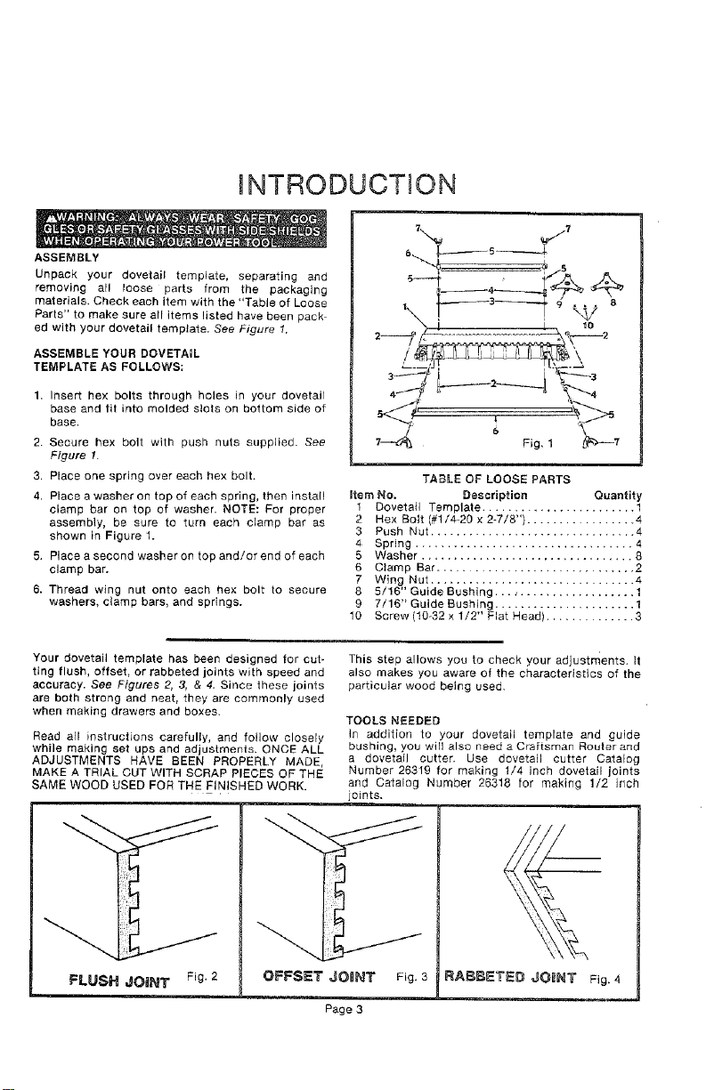
Unpack your dovetail template, separating and
removing all loose parts from the packaging
materials. Check each item with the "Table of Loose
Parts" to make sure all items listed have been pack
ed with your dovetail template. See Figure 1.
ASSEMBLE YOUR DOVETAIL
TEMPLATE AS FOLLOWS:
1. Insert hex bolts through holes in your dovetail
base and tit into molded slots on bottom side of
base.
2. Secure hex bolt with push nuts supplied. See
Figure 1.
3. Place one spring over each hex bolt.
4. Place a washer on top of each spring, then install
clamp bar on top of washer. NOTE: For proper
assembly, be sure to turn each clamp bar as
shown in Figure 1.
5. Place a second washer on top and/or end of each
clamp bar.
6. Thread wing nut onto each hex bolt to secure
washers, clamp bars, and springs.
Item No.
1
2
3
4
5
6
7
8
9
10
TABLE OF LOOSE PARTS
Description Quantity
Dovetail Template ........................ 1
Hex Bolt (#1/4-20 x 2-7/8") ................. 4
Push Nut ................................ 4
Spring .................................. 4
Washer ................................. 8
Clamp Bar ............................. 2
Wing Nut ................................
5/16" Guide Bushing...., .................. 1
7/16" Guide Bushing ...................... 1
Screw (10o32 x 1/2" Flat Head) .............. 3
Your dovetail template has been designed for cut-
ting flush, offset, or rabbeted joints with speed and
accuracy. See Figures 2, 3, & 4. Since these joints
are both strong and neat, they are commonly used
when making drawers and boxes.
Read atl instructions carefully, and follow closely
while making set ups and adjustments. ONCE ALL
ADJUSTMENTS HAVE BEEN PROPERLY MADE,
MAKE A TRIAL CUT WITH SCRAP PIECES OF THE
SAME WOOD USED FOR THE FINISHED WORK.
This step allows you to check your adjustments, it
also makes you aware of the characteristics of the
particular wood being used,
TOOLS NEEDED
In addition to your dovetail template and guide
bushing, you will also need a Craftsman Rouler and
a dovetail cutter. Use dovetail cutter Catalog
Number 26319 for making 1/4 inch dovetail joints
and Catalog Number 26318 for making 1/2 inch
joints.
FLUSH JOINT Fig.2 OFFSET JOnNT
Fig, 3
Page 3
OPERATION
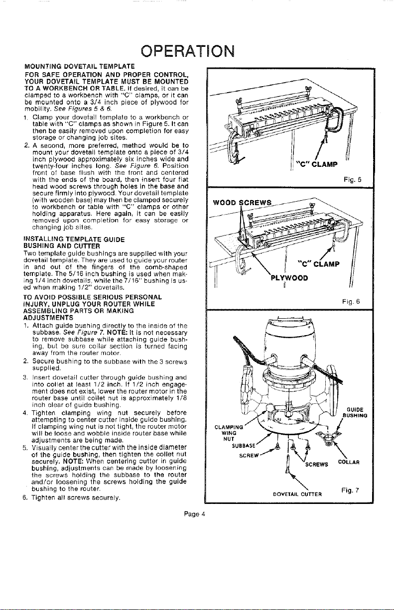
MOUNTING DOVETAIL TEMPLATE
FOR SAFE OPERATION AND PROPER CONTROL,
YOUR DOVETAIL TEMPLATE MUST BE MOUNTED
TO A WORKBENCH OR TABLE. If desired, it can be
clamped to a workbench with "C" clamps, or it can
be mounted onto a 3/4 inch piece of plywood for
mobility. See Figures 5 & 6.
1. Clamp your dovetail template to a workbench or
tab}e with "C" clamps as shown in Figure 5. It can
then be easily removed upon completion for easy
storage or changing job sites.
2. A second, more preferred, method would be to
mount your dovetai_ template onto a piece of 3/4
inch plywood approximately six inches wide and
twenty-four inches long. See Figure 6. Position
front of base flush with the front and centered
with the ends of the board, then insert four fiat
head wood screws through holes in the base and
secure firmly into plywood. Your dovetail template
(with wooden base) may then be clamped securely
to workbench or table with "C" clamps or other
holding apparatus. Here again, it can be easily
removed upon completion for easy storage or
changing job sites.
INSTALLING TEMPLATE GUIDE
RUSHING AND CUTTER
Two template guide bushings are supplied with your
dovetail template. They are used to guide your router
in and out of the fingers of the comb-shaped
template. The 5/16 inch bushing is used when mak-
ing 1/4 inch dovetails, while the 7/16" bushing is us-
ed when making 1/2" dovetails.
1"O AVOID POSSIBLE SERIOUS PERSONAL
INJURY, UNPLUG YOUR ROUTER WHILE
ASSEMBLING PARTS OR MAKING
ADJUSTMENTS
1. Attach guide bushing directly to the inside of the
subbase, See Figure 7. NOTE: It is not necessary
to remove subbase while attaching guide bush-
ing, but be sure collar section is turned facing
away from the router motor.
2. Secure bushing to the subbase with the 3 screws
supplied.
3. Insert dovetail cutter through guide bushing and
into collet at least 1/2 inch, If 1/2 inch engage-
ment does not exist, lower the router motor in the
router base until collet nut is approximately 1/8
inch clear of guide bushing.
4. Tighten clamping wing nut securely before
attempting to center cutter inside guide bushing.
If clamping wing nut is not tighL the router motor
will be loose and wobble inside router base while
adjustments are being made.
5. Visually center the cutter with the inside diameter
of the guide bushing, then tighten the collet nut
securely. NOTE: When centering cutter in guide
bushing, adjustments can be made by loosening
the screws holding the subbase to the router
and!or loosening the screws holding the guide
bushing to the router.
6, Tighten all screws securely.
Fig. 5
WOOD SCREWS
"C" CLAMP
PLYWOOD
r_
Fig. 6
SCREWS COLLAR
DOVEfAIL CUTTER Fig. 7
Page 4
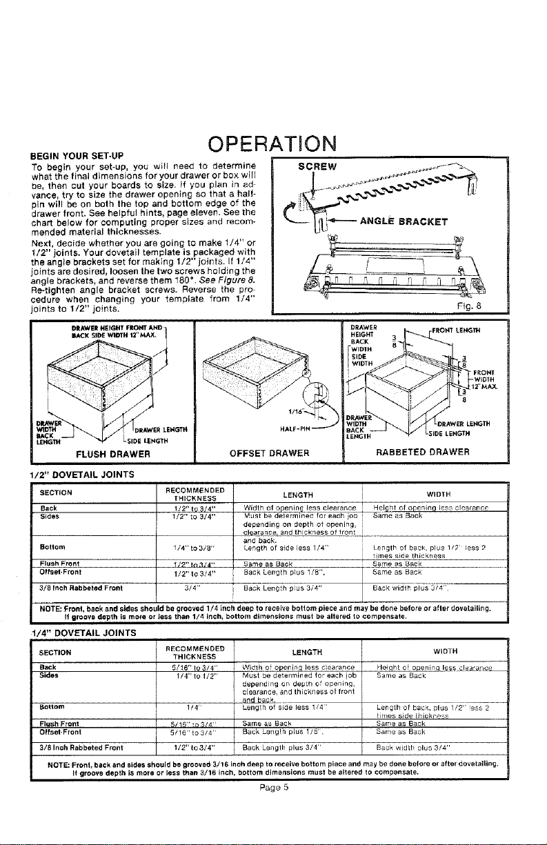
BEGIN YOUR SET-UP
OPERATION
To begin your set-up, you will need to determine
what the final dimensions for your drawer or box will
be, then cut your boards to size. if you plan in ad
vance, try to size the drawer opening so that a half-
pin will be on both the top and bottom edge of the
drawer front. See helpful hints, page eleven. See the
chart below for computing proper sizes and recom-
mended material thicknesses.
Next, decide whether you are going to make 1/4" or
1/2" joints. Your dovetail template is packaged with
the angle brackets set for making 1/2" joints. If 1/4"
joints are desired, loosen the two screws holding the
angle brackets, and reverse them 180 ° . See Figure 8.
Re-tighten angle bracket screws. Reverse the pro
cedure when changing your template from 1/4"
joints to 1/2" joints.
SCREW
L£NGTH LSIDE LENGTH
FLUSH DRAWER
OFFSET DRAWER
LENGTH
RABBETED DRAWER
/2" DOVETAIL JOINTS
SECTION
Back
Sides
Bottom
RECOMMENDED
THICKNESS
/2" t9 _/4"
1/2" to 3/4"
Flush Front
Offset.Front
3/8Inch Rabbeted Front
1/4"to 3/8"
1/?"in 314""
1/2"to 3/4"
3/4"
LENGTH WIDTH
Width of openin_ less clearance He!ght of openinc] less clearance
Must be determined, for each io_3 _ Same as Back
depending on depth of opening,
clearance, and thickness of fron[_._ ......
and back.
Length of side less 1/4" Length of back, plus 1/2 less 2
times side thickness
S_me as Back Same as Back
Back Length plus 1/8", Same as Back
Back 3/4" Back width plus 3/4'
Length plus
NOTE: Pronl, back and sides should be grooved 1/4 inch deep to receive bottom piece and may be done belore or after dovetailing,
If groove depth is mo_e or less than 1/4 inch, bottom dimensions must be altered to compensate.
1/4" DOVETAIL JOINTS
SECTION
Back
Sides
Bottom
Fl_sh Front
Offset.Front
3/8 Inch Rabbeted Front
RECOMMENDED
THICKNESS
5/t6" to $/4'
1/4" to 1/2"
1/4"
5/16"to 3/4"
1/2"to 3/4"
LENGTH
Width of opening less c ea,ance
Must be determined for each lob
depending on deptB of opening,
c_e_,ran_e, and thickness Of front
and b6g_
Lenglh of side less 1/4'
Same as Back
Back Length plus 1/8',
Back Lenglh plus 3/4"
WIDTH
Heiqht of openinq le_ea_arlcL
Same as Back
Length of back, ulus 1/2" ess 2
times side thickness
Same as Back
Same as B_ck
Back width olus 3/4"
NOTE: Front, back and sides should be grooved 3/16 inch deep to receive bottom piece and may be done before or Mter dovetaging,
R groove depth is more or less than 3/16 inch, bottom dimensions must be altered to compensale.
Page 5
Operation
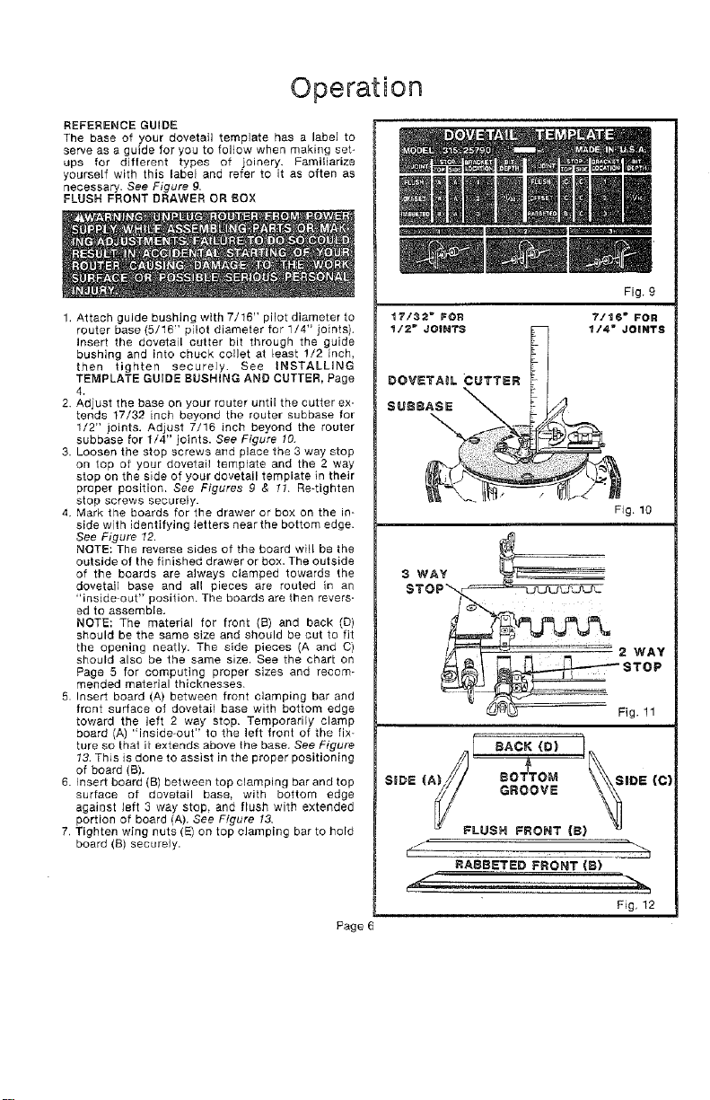
REFERENCE GUIDE
The base of your dovetail template has a label to
sewe as a guide for you to follow when making set_
ups for different types of joinery. Familiarize
yourself with this label end refer to it as often as
necessary. See Figure g,
FLUSH FRONT DRAWER OR BOX
1. Attach guide bushing with 7/16" pilot diameter to
router base {5/16" pilot diameter for 1/4" joints).
Insert the dovetail cutter bit through the guide
bushing and into chuck collet at least !/2 inch,
then tighten securely. See INSTALLING
TEMPLATE GUIDE BUSHING AND CUTTER, Page
4.
2. Adjust the base on your router until the cutter ex-
tends 17/32 inch beyond the router subbase for
1/2" joints. Adjust 7/16 inch beyond the router
subbase for 1/4" joints. See Figure 10.
3. Loosen the stop screws and place the 3 way stop
on top af your dovetail template and the 2 way
stop on the side of your dovetail template in their
proper position. See Figures 9 & 11. Re-tighten
stop screws securely.
4. Mark the boards for the drawer or box on the in-
side with identifying letters near the bottom edge.
See Figure 12.
NOTE: The reverse sides of the board will be the
outside of the finished drawer or box. The outside
of the boards are always clamped towards the
dovetail base and all pieces are routed in an
"inside out" position. The boards are then revers-
ed to assemble.
NOTE: The material for front (B) and back (D)
should be the same size and should be cut to fit
the opening neatly. The side pieces (A and C)
should also be the same size. See the chart on
Page 5 for computing proper sizes and recom-
mended material thicknesses.
5. Insert board (A) between front clamping bar and
front surface of dovetail base with bottom edge
toward the left 2 way stop. Temporarily clamp
board (A) "inside-out" to the left front of the fix-
ture so that it extends above the base. See Figure
13. This is done to assist in the proper positioning
of board (B).
6. Insert board (B) between top clamping bar and top
surface of dovetail base, with bottom edge
against left 3 way stop, and flush with extended
portion of board (A). See Figure 13.
7. Tighten wing nuts (E) on top clamping bar to hold
board (B) securely.
Page
Fig. 9
17/32 _ FOR 7/t6 _ FOR
1/2" JOINTS _ _/4" JOINTS
DOVETAIL CUTTER
SUSS
Fig. 10
S WAY
Fig. 11
sAcK r
(A)/, BOTTOM
SiDE V/ SiDE (C)
y GROOVE
LUSH FRONT (8}
j ' "_,
RABBETED FRONT (S)
Fig, 12
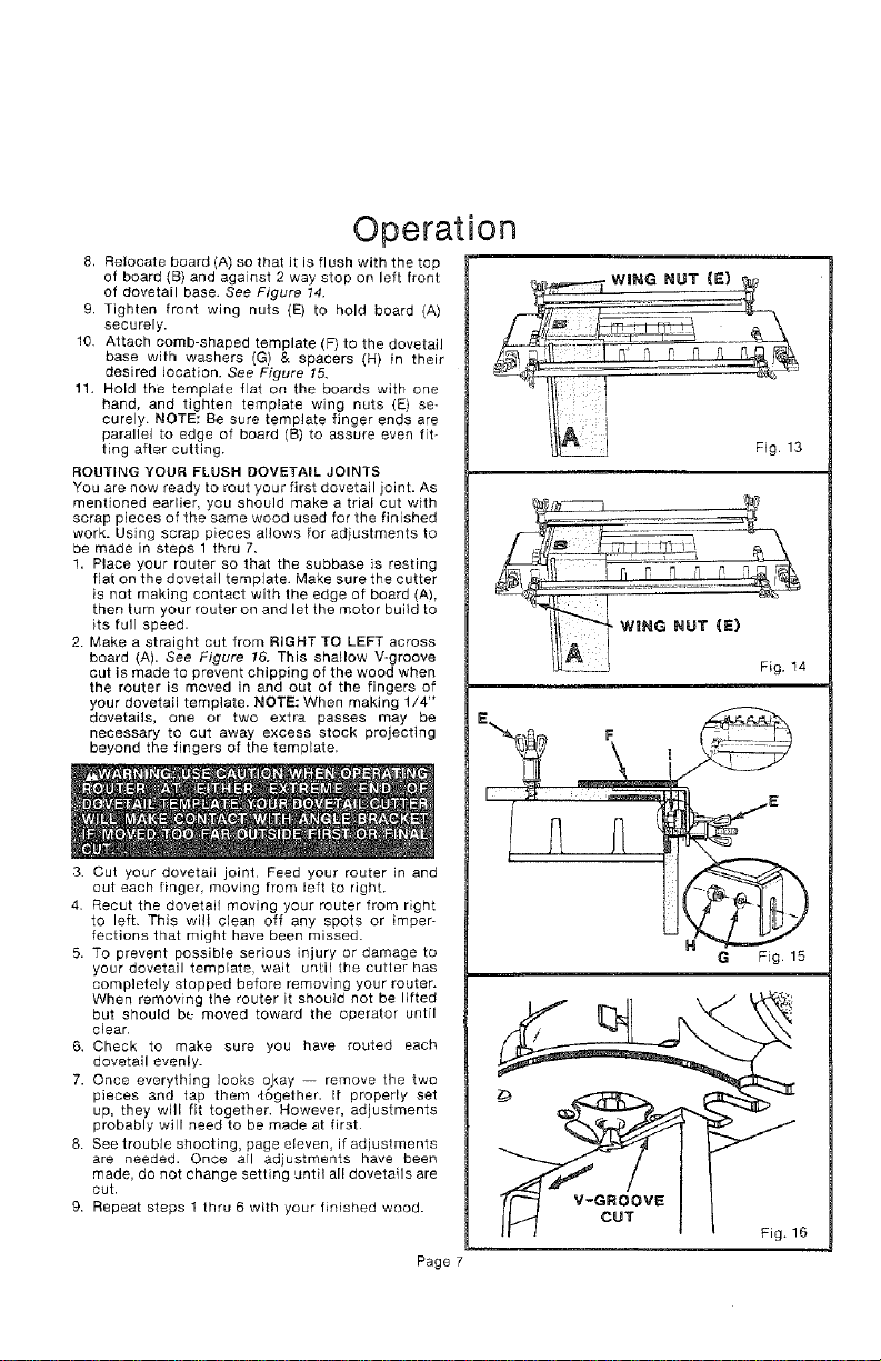
Operation
8. Relocate board (A) so that it is flush with the top
of board (B) and against 2 way stop on left front
of dovetail base. See Figure 14.
9. Tighlen front wing nuts {E) to hold board (A)
securely.
10 Attach comb-shaped template (F) to the dovetail
base with washers (G) & spacers (H) in their
desired location. See Figure 15.
11. Hold the template fiat on the boards with one
hand, and tighten template wing nuts (E) se-
curely. NOTE: Be sure template finger ends are
parallel to edge of board (B) to assure even fit-
ting after cutting.
ROUTING YOUR FLUSH DOVETAIL JOINTS
You are now ready to rout your first dovetail joint. As
mentioned earlier, you should make a trial cut with
scrap pieces of the same wood used for the finished
work. Using scrap pieces allows for adjustments to
be made in steps 1 thru 7,
1, Place your router so that the subbase is resting
fiat on the dovetail template. Make sure the cutter
is not making contact with the edge of board (A),
then turn your router on and let the motor build to
its full speed.
2. Make a straight cut from RIGHT TO LEFT across
board (A). See Figure !6. This shallow V-groove
cut is made to prevent chipping of the wood when
the router is moved in and out of the fingers of
your dovetail template. NOTE: When making 1/4"
dovetails, one or two extra passes may be
necessary to cut away excess stock projecting
beyond the fingers of the template.
3. Cut your dovetail joint. Feed your router in and
out each finger moving from left to right.
4. Recur the dovetail moving your router from right
to left. This will clean off any spots or imper-
fections that might have been missed.
5. TO prevent possible serious injury or damage to
your dovetail template, wait until the cutler has
completely stopped before removing your router.
When removing the router it should not be lifted
but should be moved toward the operator until
clear.
6. Check to make sure you have routed each
dovetail evenly.
7. Once everything looks okay -- remove the two
pieces and tap them 4ogether. It properly set
up, they will fit together. However, adjustments
probably will need to be made at first
8. See trouble shooting, page eleven, if adjustments
are needed. Once all adjustments have been
made, do not change setting until all dovetails are
cut.
9. Repeat steps I thru 6 with your finished wood.
Page
Fig. 13
Fig. 14
V-GROOVE
CUT
Fig. 16
Operation
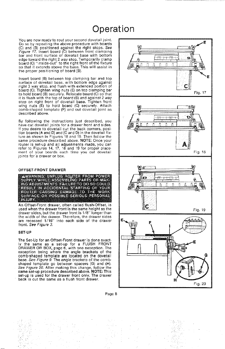
YOU are now ready to rout your second dovetait joint,
Do so by repeating the above procedure with boards
(C) and (B) positioned against the right stops, See
Figure !7. Insert board (C) between front clamping
bar and front surface of dovetail base with bottom
edge toward the right 2 way stop. Temporarily clamp
board (C) "inside-out" to the right front of the fixture
so that it extends above the base. This will assist in
the proper positioning of board (B),
Insert board (B) between top clamping bar and top
surface of dovetail base, with bottom edge against
right 3 way stop, and flush with extended portion of
board (O). Tighten wing nuts (E) on top clamping bar
to hold board (B) securely. Reiocale board (C) so that
it is flush with the top of board (B) and against 2 way
stop on right front of dovetail base. Tighten front
wing nuts (E) to hold board (C) securely. Attach
comb-shaped template (F) and cut dovetail joint as
described above.
By following the instructions just described, you
have cut dovelail joints fora drawer front and sides.
If you desire to dovetail cut the back corners, posi.
tion boards (A and D) and (O and D) in the dovetail fix-
ture as shown in Figures 18 and 19. Then follow the
same )rocedure described above, NOTE: Once your
router is set-up and all adjustments made, you can
refer to Figures 14 17, 18 and 19 for proper place-
ment of your boards each time you cut dovetail
joints for a drawer or box,
OFFSET-FRONT DRAWER
An Offset-Front drawer, often called flush-Offset, is
used when the drawer front is the same height as the
drawer sides, but the drawer front is 1/8" longer than
the width of the drawer. Therefore, the drawer sides
are recessed 1/16" into each side of the drawer
front. See Figure 3.
SET-UP
The Set-Up for an Offset-Front drawer is done exact-
ly the same as a set-up for a FLUSH FRONT
DRAWER OR BOX, page 6, with one exception, The
exception being where the angle brackets of the
comb-shaped template are Iocateci on the dovetail
base. See Figure 9. The angle brackets of the comb-
shaped template go between spacers (G) and (H).
See Figure 20. After making this change, follow the
same set-up procedure described above. NOTE: This
set-up is used for the drawer front only. The drawer
back is out the same as a flush front drawer.
E
L IL
Fig, 17
Fig. 18
Fig. 19
I
H
Fig. 20
Page 8
:i:i_I:, •
:!' :i
OPERATION
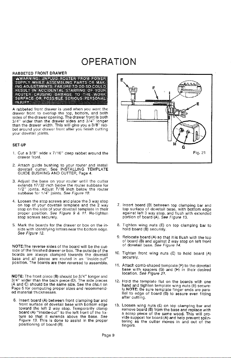
RABBETED FRONT DRAWER
A rabbeted front drawer is used when you want the
drawer front to overlap the top, bottom, and both
sides of the drawer opening. The drawer front is both
3/4" wider than the drawer sides and 3/4" longer
than the drawer width. This will give you a 3/8" rab-
bet around your drawer front after you finish cutting
your dovetail joints.
SET.UP
1. Cut a 3/8" wide x 7/16" deep rabbet around the
drawer front.
2. Attach guide bushing to your router and install
dovetail cutter. See INSTALLING TEMPLATE
GUIDE BUSHING AND CUTTER, Page 4.
3. Adjust the base on your router until the cutter
extends 17/32 inch below the router subbase for
1/2" joints, Adjust 7/16 inch below the router
subbase for 1/4" joints. See Figure 10.
4, Loosen the stop screws and place the 3 way stop
on top of your dovetail template and the 2 way
stop on the side of your dovetail template in their
proper position. See Figure g & 1t Re-tighten
stop screws securely.
5. Mark the boards for the drawer or box on the in- 8.
side with identifying letters near the bottom edge.
See Figure 12.
9.
NOTE:The reverse sides of the board will be the out-
side of the finished drawer or box. The outside of the
boards are always clamped towards the dovetail
base and all pieces are routed in an "inside out"
position. The boards are then reversed to assemble.
NOTE: The front piece (B) should be 3/4" longer and
3/4" wider than the back piece (D). The side pieces
(A and C) should be the same size. See the cha, t on
Page 5 for computing proper sizes and recommend-
ed material thicknesses.
6. Insert board (A) between front clamping bar and
front surface of dovetail base with bottom edge
toward the left 2 way stop. Temporarily clamp
board (A) "inside-out" to the left front of the fix-
ture so that it extends above the base. See
Figure 13. This is done to assist in the proper
positioning of board (B).
E
F
10.
tl.
12.
13.
Insert board (B) between top clamping bar and
top surface of dovetail base, with bottom edge
against left 3 way stop, and flush with extended
portion of board (A), See Figure 13.
Tighten wing nuts (E) on top clamping bar to
hold board (B) securely.
Relocate board (A) so that it is flush with the top
of board (B) and against 2 way stop on left front
of dovetail base. See Figure 14.
Tighten front wing nuts (E) to hold board (A)
securely.
Attach comb-shaped template (F) to the dovetail
base with spacers (G) and (H) in their desired
location. See Figure 2!,
Hold the template flat on the boards with one
hand and tighten template wing nuts (E) secure-
ly.NOTE: Be sure template finger ends are para-
llel to edge of board (B) to assure even fitting
after cutting.
Loosen wing nuts (E) on top clamping bar and
remove board (B) from the base and replace with
a sc_:ap piece of the same wood. This will pro-
vide support for board (A) and help prevent splin-
terin_ as the cutter moves in and out of the
fingers.
Page 9
OPERATION
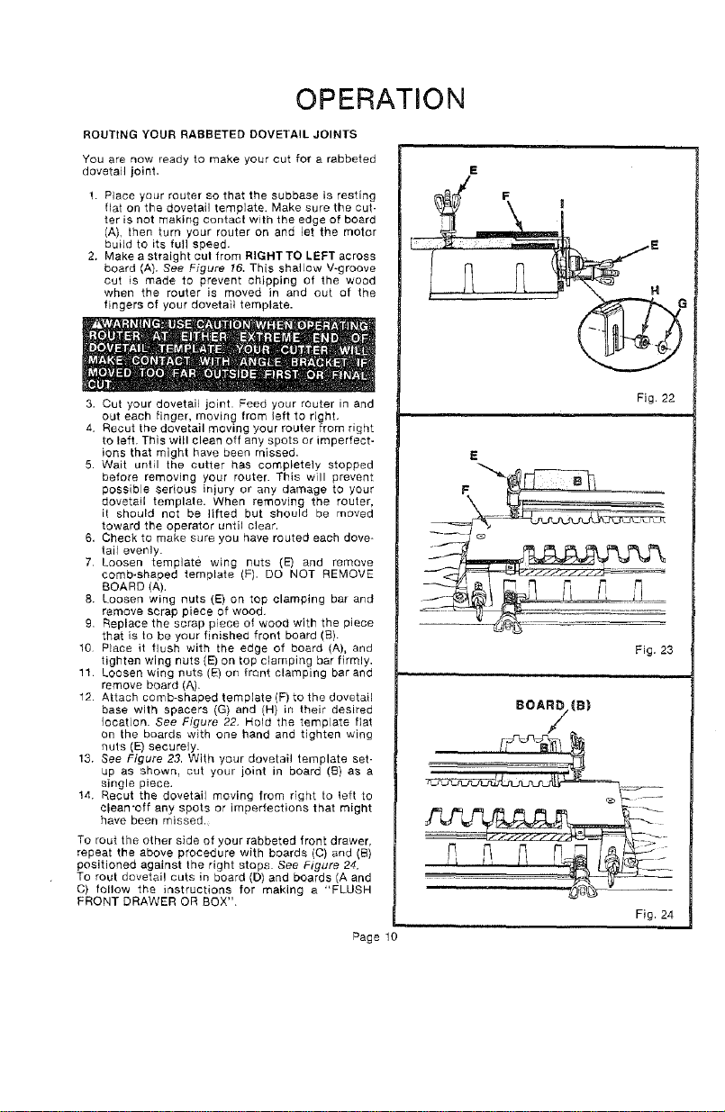
ROUTING YOUR RABBETED DOVETAIL JOINTS
You are now ready to make your cut for a rabbeted
dovetail joint.
1. Place your router so that the subbase is resting
flat on the dovetail template. Make sure the cut-
ter is not making contacl with the edge of board
(A), then turn your router on and let the motor
build to its full speed.
2. Make a straight cut from RIGHTTO LEFT across
board (A}. See Figure 16, This shallow V-groove
cut is made to prevent chipping of the wood
when the router is moved in and out of the
fingers of your dovetail template.
3. Cut your dovetail joint. Feed your router in and
out each finger, moving from left to right.
4. Recut the dovetail moving your router from right
to left. This will clean off any spots or imperfect-
ions that might have been missed.
5. Wait until the cutter has completely stopped
before removing your router. This will prevent
possible serious injury or any damage to your
dovetail templale. When removing the router,
it should not be lifted but should be moved
toward the operator until clear.
6, Check to make sure you have routed each dove-
tail evenly.
7. Loosen template wing nuts (E) and remove
comb-shaped template (F). DO NOT REMOVE
BOARD (A).
8. Loosen wing nuts (E) on top clamping bar and
remove scrap piece of wood.
9. Replace the scrap piece of wood with the piece
that is to be your finished front board (B).
10 Place it flush with the edge of board (A), and
tighten wing nuts (E) on top clamping bar firmly.
11. Loosen wing nuts (E) on front clamping bar and
remove board (A).
12. Attach comb-shaped template (F) to the dovetail
base with spacers (G) and (H} in their desired
location. See Figure 22. Held the template fiat
on the boards with one hand and tighten wing
nuts (E) securely.
13. See Figure 23. With your dovetail template set-
up as shown, cut your joint in board (B) as a
single piece.
14. Recut the dovetail moving from right to left to
clean*off any spots or imperfections that might
have been missed.
To rout the other side of your rabbeted front drawer,
repeat the above procedure with boards (C) and (B}
positioned against the right stops. See Figure 24.
To rout dovetail cuts in board (D) and boards (A and
C) follow the instructions for making a "FLUSH
FRONT DRAWER OR BOX".
Page 10
Fig 22
=
E
F
Fig, 23
Fig. 24
HELPFUL HINTS
• Once all adjustments are made, do not make any
urther changes until all dovetails are cut.
• Always clamp workpiece securely for cutting,
° Rout dovetails from the front on_y,
• A safe operator is one who thinks ahead,
• Do not raise or lower your router or cutter while
the bit is between the dovetail template fingers.
Keep router base fiat against template.
• Always wear eye protection when routing.
• Make certain the ends of all boards are square.
• Make eet-up adjustments carefully. Then double
check. Measure twice and cut once.
• DO NOT use warped boards.
• Keep cutters clean and properly sharpened.
• Be consistent when selecting the thickness of
your boards.
= Don't let familiarity make you careless.
= Always bevel the drawer front for an offset-front
drawer.
o Study all safety rules and do the job safely.
t Plan your drawer opening so that the boards will
be in increments of 7/8 {nch for 1/2 inch joints, or
29/64 inch increments for 1/4 inch joints. This wi{l
allow a half-pin to be on both the top and bottom
edge of the drawer front. Don't forget to allow for
clearances.
• NEVER place your hands in jeopardy.
• Make certain clamps can't loosen while in use.
• Test dlfficuit set-ups on scrap -- Don't waste
lumber.
• Plan each operation before you begin.
• THINK SAFETY BY THINKING AHEAD.
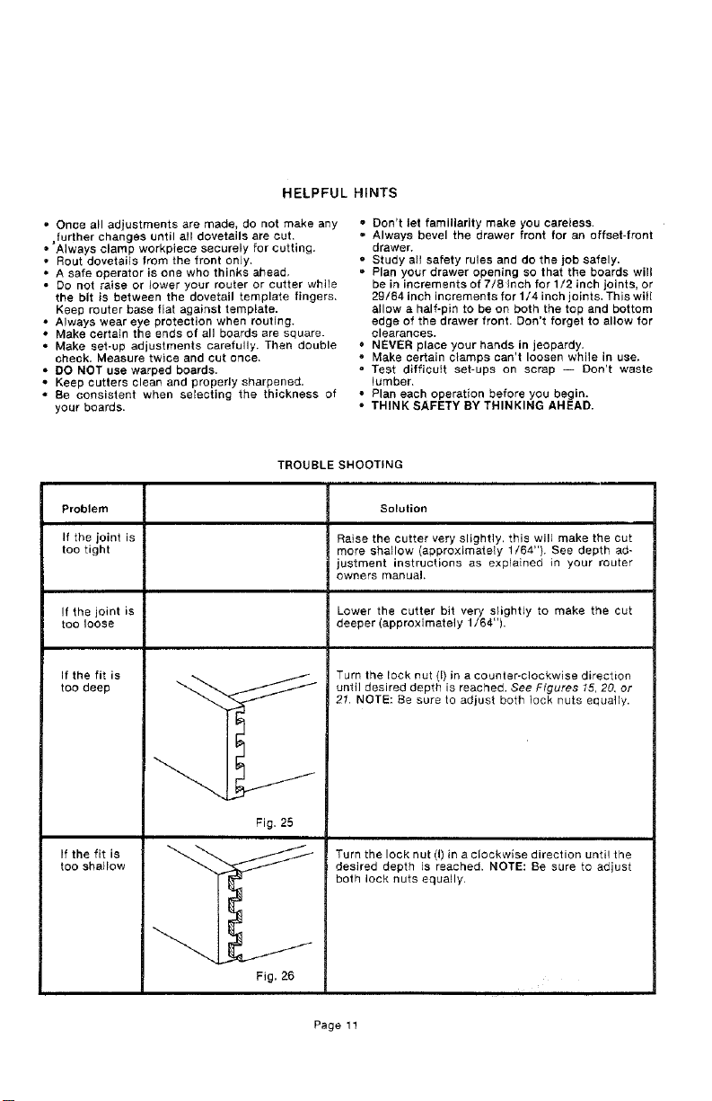
TROUBLE SHOOTING
Problem Solution
If the joint is Raise the cutter very slightly, this will make the cut
too tight more shallow (approximately 1/64"). See depth ad-
justment instructions as explained in your router
owners manual,
!f the joint is Lower the cutter bit very slightly to make the cut
too loose deeper (approximately 1/64").
If the fit is
too deep
If the fit is
too shallow
Fig. 26
Turn the lock nut (I) in a counter-clockwise direction
until desired depth is reached. See Ffgures 15, 20, or
21. NOTE: Be sure to adjust both lock nuts equally.
Turn the lock nut (I) in a clockwise direction until the
desired depth is reached. NOTE: Be sure to adjust
both lock nuts equally,
Page 11
o
o,I
rr
I.g
Z
,.,I
0
r-,
Z
=E
I--
u.
<
n,*
_,o
\
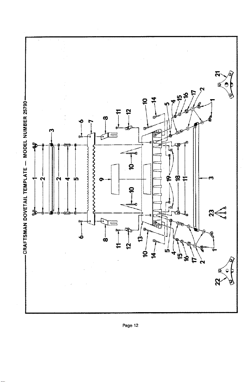
Page 12

W
W
k-
0.
LO
W
Z 0
d
.J
V.
o
0
k-
0
...... . • . • . . . , . . , .....
.... r • • • • ....... , .....
_ : : :_- ' • : : ' : : : • :o° : _9"
NN
d
Z
E
I=1
E
0
Page 13

NOTES
Page'14

NOTES
Page 15
OWNERS
MANUAL
MODEL NO.
315.25790
HOW TO ORDER
REPAIR PARTS
R
DOVETAIL TEMPLATE
FOR USE WITH ALL CRAFTSMAN ROUTERS
ALWAYS MENTION CATALOG NUMBER 25790
WHEN COMMUNICATING WITH US REGARDING
YOUR CRAFTSMAN DOVETAIL TEMPLATE.
WHEN ORDERING REPAIR PARTS, ALWAYS GIVE
THE FOLLOWING INFORMATION:
, PART NUMBER
,_ MODEL NUMBER
315.25790
PART DESCRIPTION
e NAME OF ITEM
DOVETAIL TEMPLATE
AIr parts listed may be ordered from any Sears Ser-
vice Center and most Sears stores.
If the parts you need are not stocked locally, your
order will be electronically transmitted to a Sears
Repair Parts Distribution Center for handling.
SEARS, ROEBUCK AND CO., Hoffman Estates, IL 60179
