NOTE:
Product may vary slightly from the item pictured due to model upgrades. This manual may be subject to updates or changes.
Up to date manuals are available through our website at www.lifespanfitness.com.au
Read all instructions carefully before using this product.
Retain this owner’s manual for future reference.
IMPORTANT
All nuts and bolts are to be checked and tightened on a regular basis. This includes pedals and
other moving parts. Failure to do so may cause damage to your threads and void your warranty.
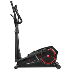
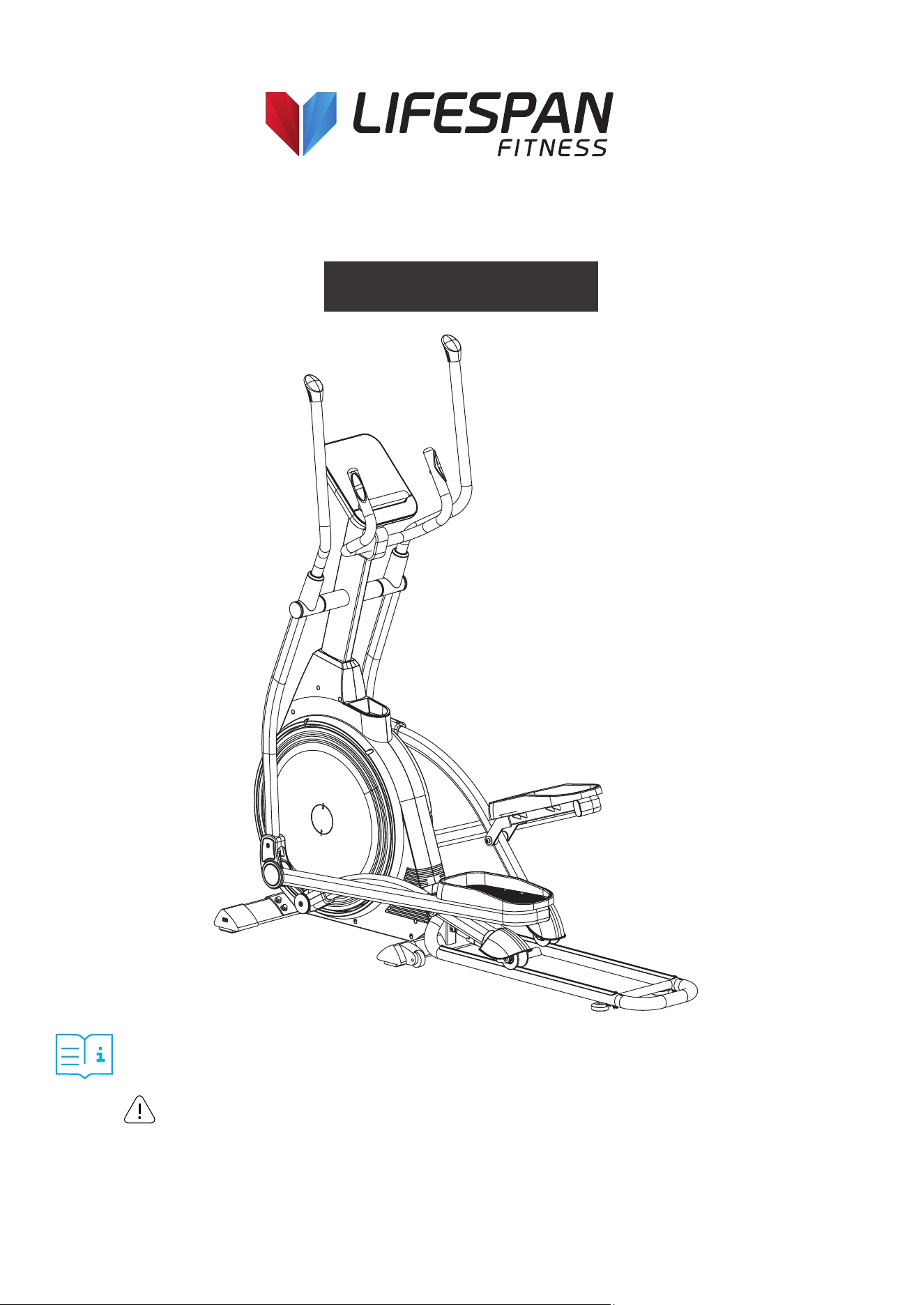
XT-39 Folding Cross Trainer
USER MANUAL

2
TABLE OF
CONTENTS
I. Important Safety Instructions . . . . . . . . . . . . . . . . . . . . . . . . . . . . . . . 03
II. Care Instructions . . . . . . . . . . . . . . . . . . . . . . . . . . . . . . . . . . . . . . . . . . . . . 04
III. Exploded Diagram . . . . . . . . . . . . . . . . . . . . . . . . . . . . . . . . . . . . . . . . . . . . 05
IV. Parts List . . . . . . . . . . . . . . . . . . . . . . . . . . . . . . . . . . . . . . . . . . . . . . . . . . . . . . 06
V . Assembly Instructions . . . . . . . . . . . . . . . . . . . . . . . . . . . . . . . . . . . . . . . 07
VI. Folding Guide . . . . . . . . . . . . . . . . . . . . . . . . . . . . . . . . . . . . . . . . . . . . . . . . 13
VII. Operation Manual . . . . . . . . . . . . . . . . . . . . . . . . . . . . . . . . . . . . . . . . . . . . 15
VIII. Exercise Guide . . . . . . . . . . . . . . . . . . . . . . . . . . . . . . . . . . . . . . . . . . . . . . . 23
IX. Warranty . . . . . . . . . . . . . . . . . . . . . . . . . . . . . . . . . . . . . . . . . . . . . . . . . . . . . . 25
| TABLE OF CONTENTS

3IMPORTANT SAFETY INSTRUCTIONS |
I. IMPORTANT SAFETY
INSTRUCTIONS
WARNING: Read all instructions before using this machine.
It is important your machine receives regular maintenance to prolong its useful life. Failing to
regularly maintain your machine may void your warranty.
Please keep this manual with you at all times.
• It is important to read this entire manual before assembling and using the equipment. Safe and
effective use can only be achieved if the equipment is assembled, maintained, and used properly.
PLEASE NOTE: It is your responsibility to ensure that all users of the equipment are informed of all
warnings and precautions.
• Before starting any exercise program, you should consult your doctor to determine if you have any
medical or physical conditions that could put your health and safety at risk, or prevent you from
using the equipment properly. Your doctor’s advice is essential if you are taking medication that
affects your heart rate, blood pressure or cholesterol level.
• Be aware of your body’s signals. Incorrect or excessive exercise can damage your health. Stop
exercising if you experience any of the following symptoms: pain, tightness in your chest, irregular
heartbeat, and extreme shortness of breath, lightheadedness, dizziness, or feelings of nausea. If you
do experience any of these symptoms, you should consult your doctor before continuing with your
exercise program.
• Keep children and pets away from the equipment. This equipment is designed for adult use only.
• Use the equipment on a solid, flat level surface with a protective cover for your floor or carpet.
To ensure safety, the equipment should have at least 2 meters of free space around it.
• Before using the equipment, check that the nuts and bolts are securely tightened. If you hear any
unusual noises coming from the equipment during use and assembly, stop immediately. Do not use
the equipment until the problem has been rectified.
• Wear suitable clothing while using the equipment. Avoid wearing loose clothing that may get caught
vin the equipment or that may restrict or prevent movement.
• This equipment is designed for indoor and family use only.
• Care must be taken when lifting or moving the equipment so as not to injure your back.

4 | CARE INSTRUCTIONS
• Always keep this instruction manual and assembly tools at hand for reference.
• The equipment is not suitable for therapeutic use.
• The pulse or heart rate sensors are not medical devices. Various factors, including the user’s
movement, may affect the accuracy of heart rate readings. The pulse sensors are intended only as
exercise aids in determining heart rate trends in general.
II. CARE INSTRUCTIONS
a. Lubricate moving joints with grease after periods of usage.
b. Be careful not to damage plastic or metal parts of the machine with heavy or sharp objects.
c. The machine can be kept clean by wiping it down using dry cloth.
d. All nuts and bolts are to be checked and tightened on a regular basis. This includes pedals and other
moving parts. Failure to do so may cause damage to your thread and void your warranty.
5 EXPLODED DIAGRAM |
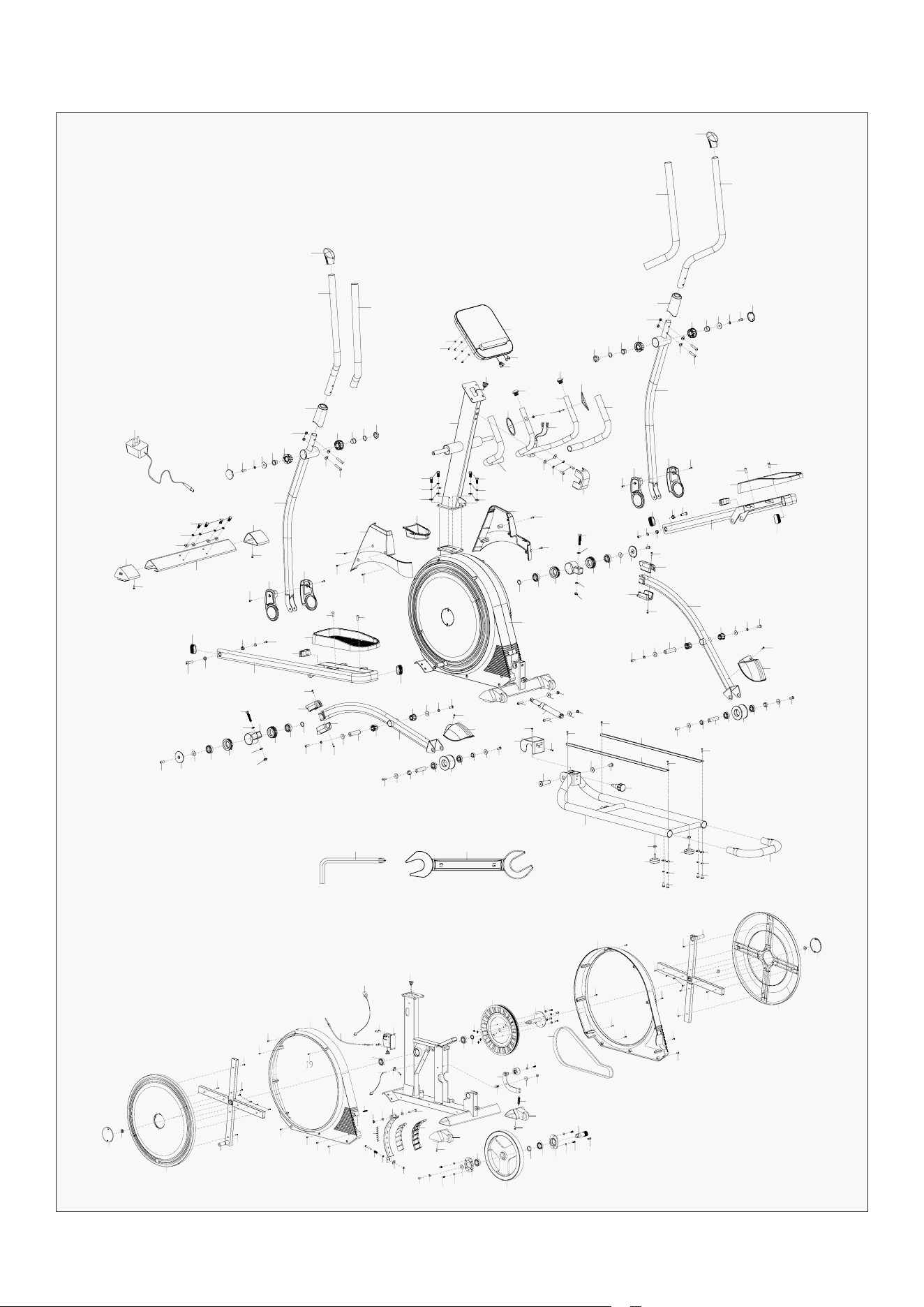
III. EXPLODED DIAGRAM
21
22R
23
24
32
31
33
11
12
34
26
31
32
28
25R
36R
36L
16R
37
37
42
49
10
41
40
18
51
45
46
30
20
47
47
48
48
10
26
51
18
12
18
59
11
46
53
53
52
46
11
12
54R
12
39
38R
43
44
12
12
35
35
13
18
19
12
11
11
11
10
17
10
10
9
5
6
8
1a
1
1b
2
3
80
14
29
30
31
32
27
28
25L
61R
63
11
10
61L
62
60
35
36L
36R
35
19
19
18
12
12
37
44
42
43
41
40
37
40
38L
18
51
49
10
26
48
47
46
45
12
10
50
48
47
30
51
12
11
18
46
52
53
12
12
12
18
59
65
66
78
77
79
66
68
35
69
70
71
71
12
46
55
35
35
72
72
73
73
75
75
74
S13-S15
B
A
S5
11
11
76
76
55
46
12
56
57
57
58
67
35
10
26
26
10
11
46
53
46
46
55
55
55
57
57
58
54L
39
16L
62
24
26
32
31
33
11
12
34
125
23
21
22L
15
4
8
6
7
15
5
27
30
29
81
82
83
84
19
19
19
19
19
18
85L
123
124
19
19
18
18
18
98
96
120
119
86
18
122
121
18
96
95
99
100
101
102
103
104
88
12
11
109
110
86
63
62
46
26
93
90
91
92
19
19
19
19
19
19
19
84
83
81
82
18
18
18
18
85R
88
89
87
86
62
111
112
118L
114
113
115
112
110
116
117
118R
108
106
105
107
41
109
97
94
26

6
IV. PARTS LIST
HARDWARE PACKAGE
No. Description Qty
1 Computer
1
2 Washer D4
4
3 Bolt M4
4
4 Middle handlebar
1
5 Grip foam
2
6 Handle pulse plate
2
7 Screw ST4.2*19
2
8 End cap ф25*26
2
9 Handle pulse wire
2
10 Washer d8*Φ20*2
16
11 Spring washerd8
21
12 Bolt M8*20*S5
19
13 Cover
1
14 Handlebar post
1
15 Bolt M8*25*S13
4
16L/R Handlebar post cover
1
17 Supporter
1
18 Screw ST4.2*16
21
19 Screw ST4.2*19
25
20 Main frame
1
21 End cap
2
22 Handlebar L/R
1
23 Grip foam
2
No. Description Qty
24 Handlebar cover
2
25L/R Reciprocating bar L/R
1
26 Nylon nut M8*H7.5*S13
10
27 Arc washerd8*Φ20*2*R16
4
28 Bolt M8*40*15*S5
4
29 Spacer Φ30*Φ20*9
2
30 Wave washerd19*Ф25*0.3
4
31 BushingΦ27*1*Φ19.2*16
4
32 BushingΦ50*Φ21*20
4
33 Washer d8*Φ32*2
2
34 Handlebar cover
2
35 Screw ST4.2*13
8
36 Swing bar cover L/R
2
37 End cap PT25*50
4
38 Linkage L/R
1
39 Bolt Φ10*34*M6*15*S6
2
40 BushingΦ18*1.5*Φ14.6*5*Φ10.1
4
41 Washer d6*Φ16*1.5
3
42 Bolt M6*15*S5
2
43 End cap J60*30*15
2
44 Pedal
2
45 Cover
2
46 Washer d8*Φ25*2
11
| PARTS LIST
#10 D8*ф20*2 - 4pcs
#11 D8 - 4pcs
#15 M8 *25*S13 - 4pcs
#18 ST4.2*16 - 2pcs
#19 ST4.2*19 - 3pcs
#26 M8*H7.5*S13 - 4pcs
A S5
B S13 - S15
#27 D8*ф20*2*R16 - 4pcs
#28 40*15*2*S5 - 4pcs
#35 ST4.2*13 - 2pcs

7ASSEMBLY INSTRUCTIONS |
No. Description Qty
47 BearingR12
4
48 BushingΦ60*16.6Φ41.18*13.11
4
49 Bolt M8*50*20*S14
2
50 Connector
2
51 Cover
4
52 Shaft
2
53 BushingΦ32*3.3*Φ28*20.5*Φ19.1
4
54L/R
Linkage
1
55 Spacerφ22*φ17.1*8.8
4
56 Shaft for transportation wheel
2
57 Bearing6003
4
58 Roller
2
59 Wheel cover
2
60 Front stabilizer
1
61/l/R
End cap L/R
1
62 Screw ST4.2*16
4
63 Bolt M8*20*S13
5
64 Rail
1
65 Cover
1
66 Screw ST4*19
2
67 Knob M16
1
68 Spindle
1
69 Washer d10*Φ25*2
1
70 Bolt M10*20*S6
1
71 Alum plate
2
72 Nut M8*H5.5*S14
2
73 Footpad
2
74 Handlebar
1
75 Arc washerd8*Φ20*2*R19
4
76 Bolt M8*16*S5
4
77 Gas spring
1
78 Bolt M8*30*S5
1
79 Bolt M8*45*20*S5
1
80 Trunk wire 1
1
81 Crank cover
2
82 Nut M10*1.25*H7.5*S14
2
83 Turntable
2
84 Crank
2
85 Chain cover
1
86 Bearing6004
3
87 SpacerΦ25*Φ20.2*4
1
No.
Description
Qty
88 Nylon nut M6*H6*S10
5
89 Belt plate
1
90 Shaft
1
91 Spring washerd6
4
92 Bolt M6*16*S5
4
93 Belt
1
94 Plastic connector
1
95
Bolt M8*55*13*S14
1
96 Washer d8*Φ16*1.5
2
97 Magnetic plate
1
98 Screw ST3.0*10
8
99 Magnetic location grid
2
100 Magnet
7
101 Bolt M6*65*S10
1
102
Spring
1
103 Nut M6*H5*S10
1
104 Washer φ6*φ18*2
1
105 Idler rod
1
106 Idler
1
107 Bolt M6*12*S10
1
108 Spring
1
109 Bolt M5*16
4
110 Washer d5*Φ13*1
4
111 Washer d8*Φ28*2
1
112 Bearing holder
2
113 Flywheel
1
114 SpacerΦ30*Φ25*6.5
1
115 Bearing61905
1
116 Flat key 8*7*25
1
117 Flywheel axle
1
118L/R End cap L/R
1
119 Sensor holder
1
120 Sensor
1
121 Trunk wire 2
1
122 Motor
1
123 Resistance control cable
1
124 Adapter trunk wire
1
125 Adapter
1
A Wrench S5
1
B Spanner S13-15
1
8 | ASSEMBLY INSTRUCTIONS
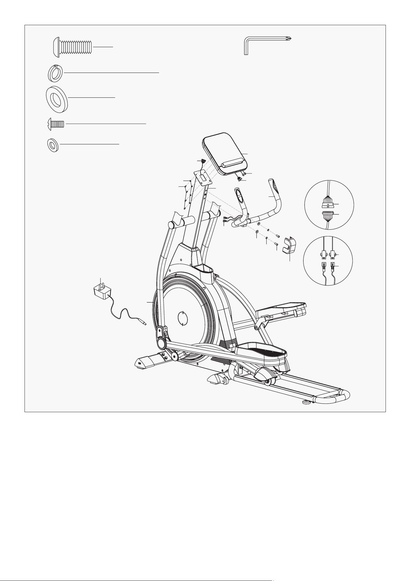
V. ASSEMBLY INSTRUCTIONS
1. Connect trunk wire 1 (80) on the handlebar post (14) with trunk wire 2 (121) on the main frame (20)
well, then put the wires inside of main frame (20).
2. Fix handlebar post (14) to main frame (20) with bolts (15), spring washers (11) andw ashers (10) using
spanner (B).
3. Secure handlebar post covers (16L/R) with screws (19), then secure them on the handlebar post (14)
with screws (18) and tighten with wrench (A).
NOTE: Some nuts and bolts are attached on the parts, and you will need to remove and
re-attach it to the connecting parts.
STEP 1
#10 D8*ф20*2 - 4pcs
#11 D8 - 4pcs
#15 M8 *25*S13 - 4pcs
#18 ST4.2*16 - 2pcs
#19 ST4.2*19 - 3pcs
A S5
B S13 - S15
14
17
15
16R
18
19
80
121
11
10
20
19
19
18
16L
121
80
10
11
15
9ASSEMBLY INSTRUCTIONS |
#10 D8*ф20*2 - 4pcs
#11 D8 - 4pcs
#63 M8 *20*S13 - 4pcs
#12 M8 *20*S5 - 4pcs
B S13 - S15
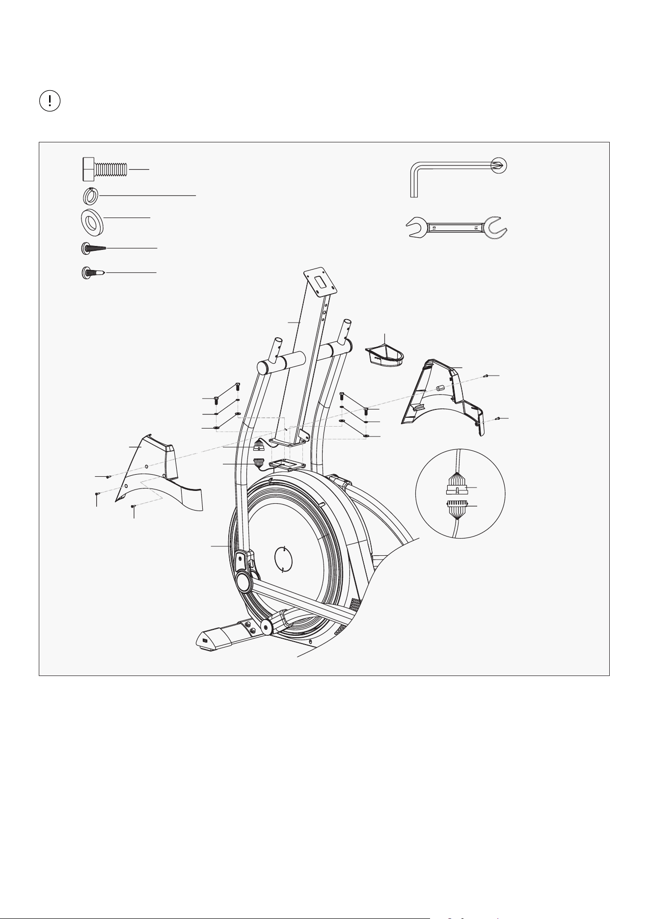
1. Remove bolts (63), spring washers (11) and
washers (10) from front stabilizer (60) with
spanner (B).
2. Attach front stabilizer (60) to main frame
(20) with bolts (63), spring washers (11) and
washers (10) with spanner (B).
1. Remove bolts (12) from pedal (44) by wrench
(A), then attach pedal (44) to Linkage (38L/R)
with bolts (12) by wrench (A).
STEP 2
STEP 3
20
63
63
11
11
10
10
60
A S5
12
12
44
38R
38L
12
44
12
10 | ASSEMBLY INSTRUCTIONS
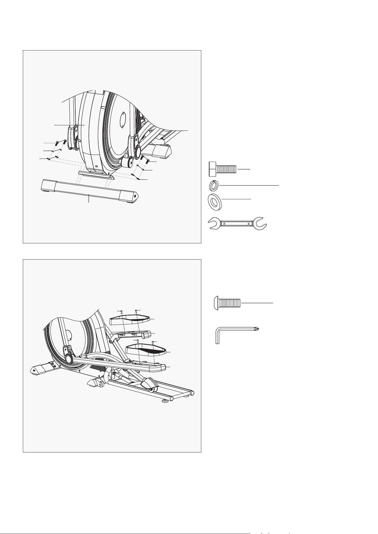
STEP 4
1. As showed in Figure I, pull knob (67) out loosely and rotate counterclockwise about 90 degrees to fold
rail (64).
2. Take out bolts (76), spring washers (11) and washers (75) from handlebar (74) by wrench (A).
3. Insert handlebar (74) into rail (64), secure them using bolts (76), spring washers (11) and washers (75)
by wrench (A).
4. Secure screws (35) in rail (64) by wrench (A).
A S5
74
35
35
75
75
64
67
76
76
11
11
#75 D8*ф20*2*13 - 2pcs
#35 ST4.2*13 - 2pcs
#11 D8 - 4pcs
#76 M8 *16*S5 - 4pcs
11ASSEMBLY INSTRUCTIONS |
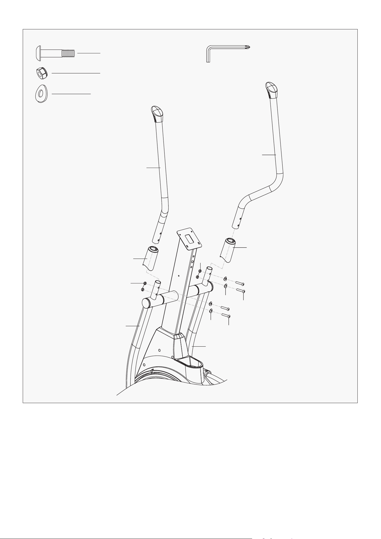
1. Put handlebar covers (24) into handlebar (22L/R),
2. Attach handlebar (22L/R) to reciprocating bar (25L/R) with bolts (28), arc washers (27) and nylon nut
(26) by wrench (A).
STEP 5
A S5
#28 M8 *10*15*S5 - 4pcs
#26 M8 *H7.5*S13 - 4pcs
#27 D8 *ф20*2*R16 - 4pcs
22L
22R
24
24
26
26
28
28
27
27
25R
25L
12
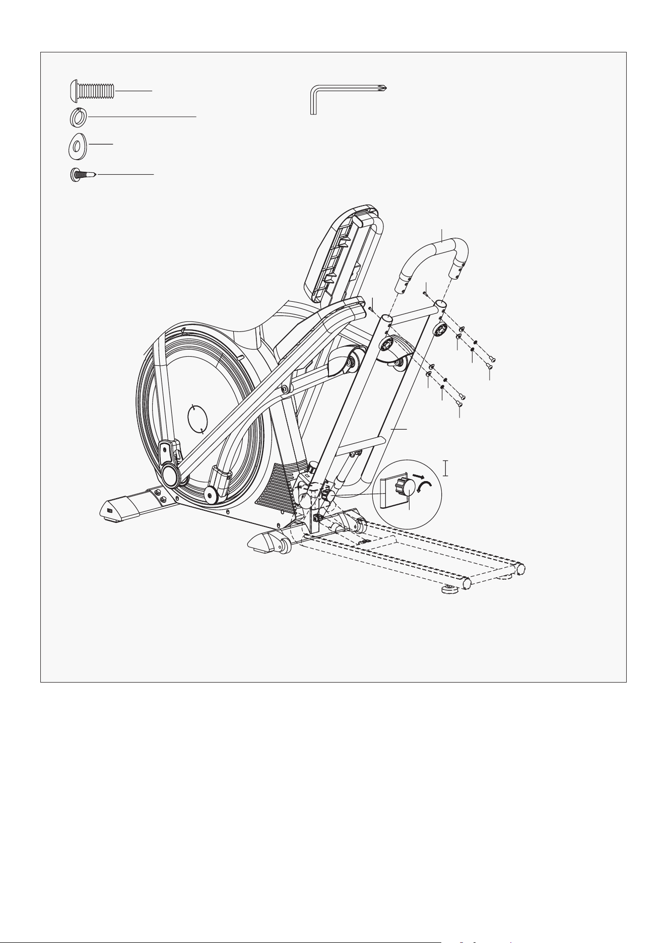
STEP 6
1. Remove bolts (12), spring washer (11) and washers (10) from handlebar post (14) with spanner (A).
2. Draw the handle pulse wire (9) through the hole of handlebar post (14).
3. Fix middle handlebar (4) to handlebar post (14) with bolts (12), spring washer (11) and washers (10)
from handlebar post (14) using spanner (A).
4. Connect computer wire (1a) with handle pulse wire (9) and computer wire (1b) with trunk wire (80).
5. Take out the bolts (3) and washers (2) from the back of computer (1) with spanner (A). Then attach
computer (1) to handlebar post (14) with bolts (3) and washers (2) using spanner (A).
6. Insert adapter wire (125) to power hole on the main frame (20), then plug the adapter into an outlet.
Attention: Turn off the power when equipment is not in use.
| ASSEMBLY INSTRUCTIONS
A S5
#12 M8 *20*S5 - 2pcs
#11 D8 - 2pcs
#10 D8 *ф20*2 - 2pcs
#2 D4 *ф12*1 - 4pcs
#3 M4*12 - 4pcs
1
1a
1a
1b
1b
4
14
80
2
3
9
10
20
125
11
12
13 9
80
13ASSEMBLY INSTRUCTIONS |
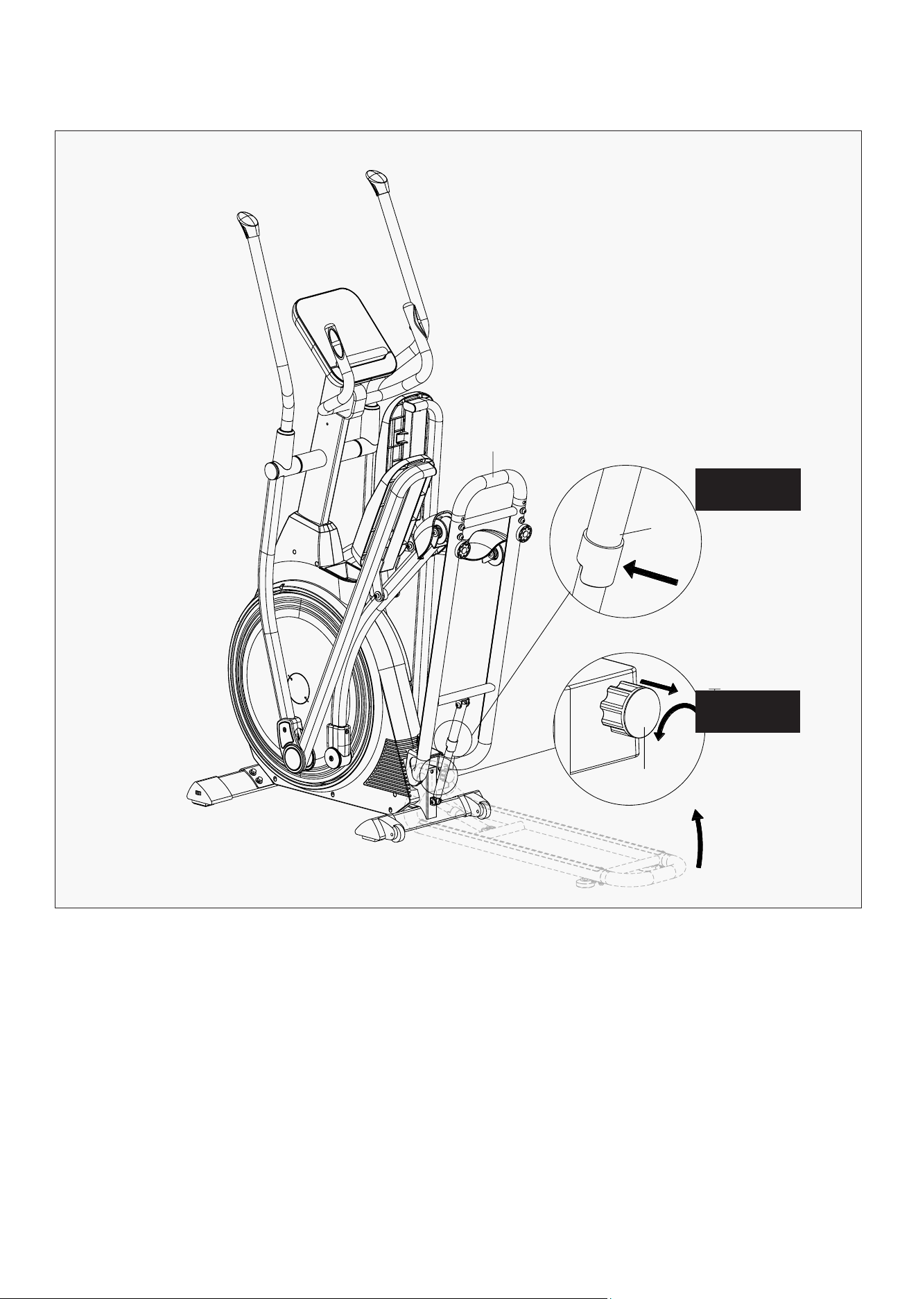
VI. FOLDING GUIDE
The cross trainer can be folded away for storage when not in use.
Folding Instructions:
As shown in Figure I, pull knob (67) out loosely and rotate it counterclockwise about 90 degrees, then
pull the handlebar (74) up until the gas spring (77) is fully extended and clicks into place. Ensure the rail
is fixed.
Un-folding Instructions:
As showed in Figure II, hold the handlebar (74), then tap on the gas spring (77) to release. It will than
gently lower until the rail touches the ground. Turn the knob (67) counterclockwise about 90
degrees, the knob (67) will reset automatically, and you can use it.
74
77
67
Figure II
Figure I
14 | ASSEMBLY INSTRUCTIONS
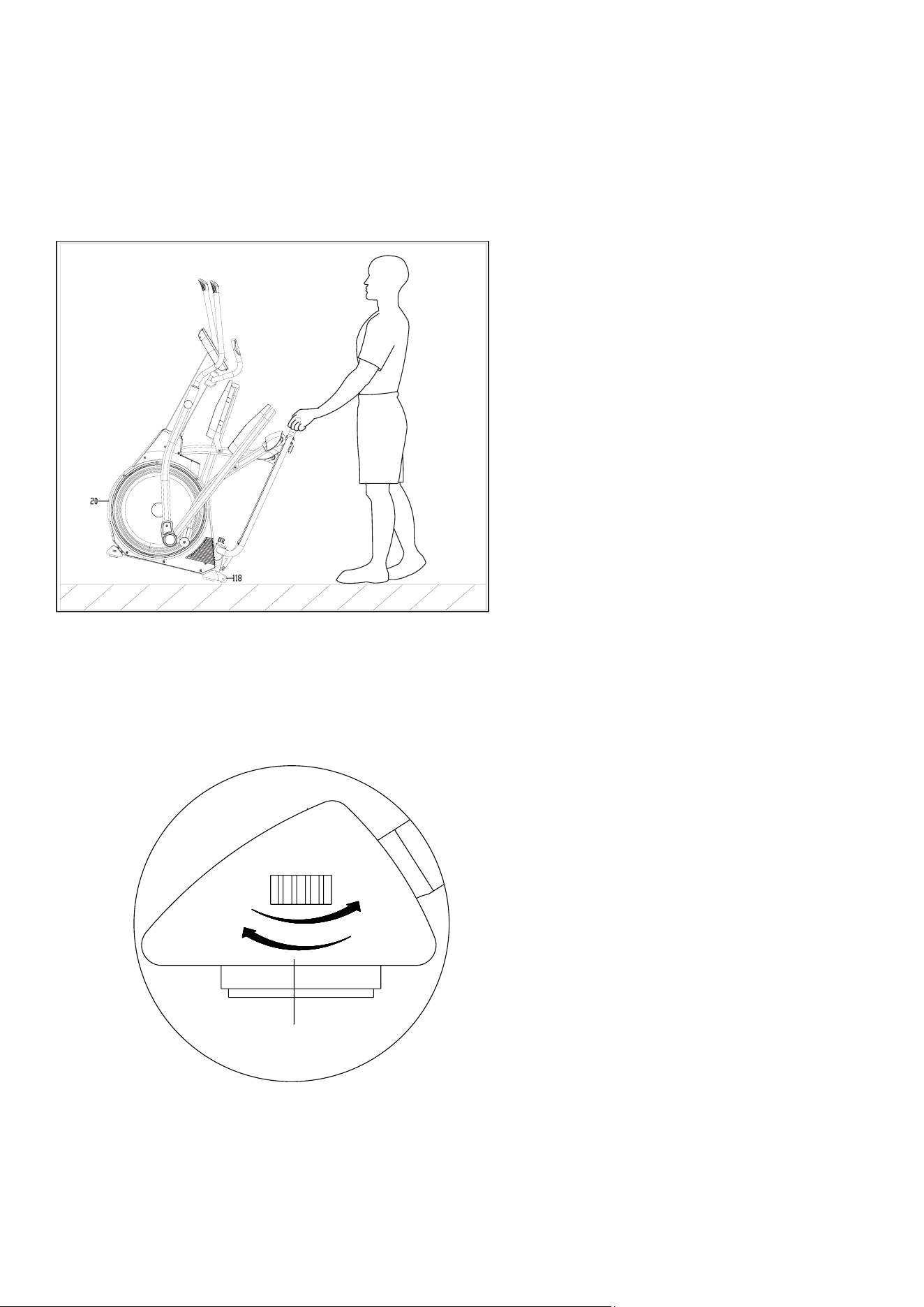
TRANSPORTING & FLOOR LEVELERS
1. Moving the Machine
2. Adjusting the Floor Levelers
To move the machine, push the handlebar
until the transportation wheels (118) on the
main frame (20) touch the ground. With the
wheels on the ground, you can transport the
bike to the desired location at ease.
When the equipment is on an uneven
surface, you can adjust both foot pads on
end cap (61) as pictured. Turning it left or
right will make the pads come down more or
go back up.
15OPERATION MANUAL |
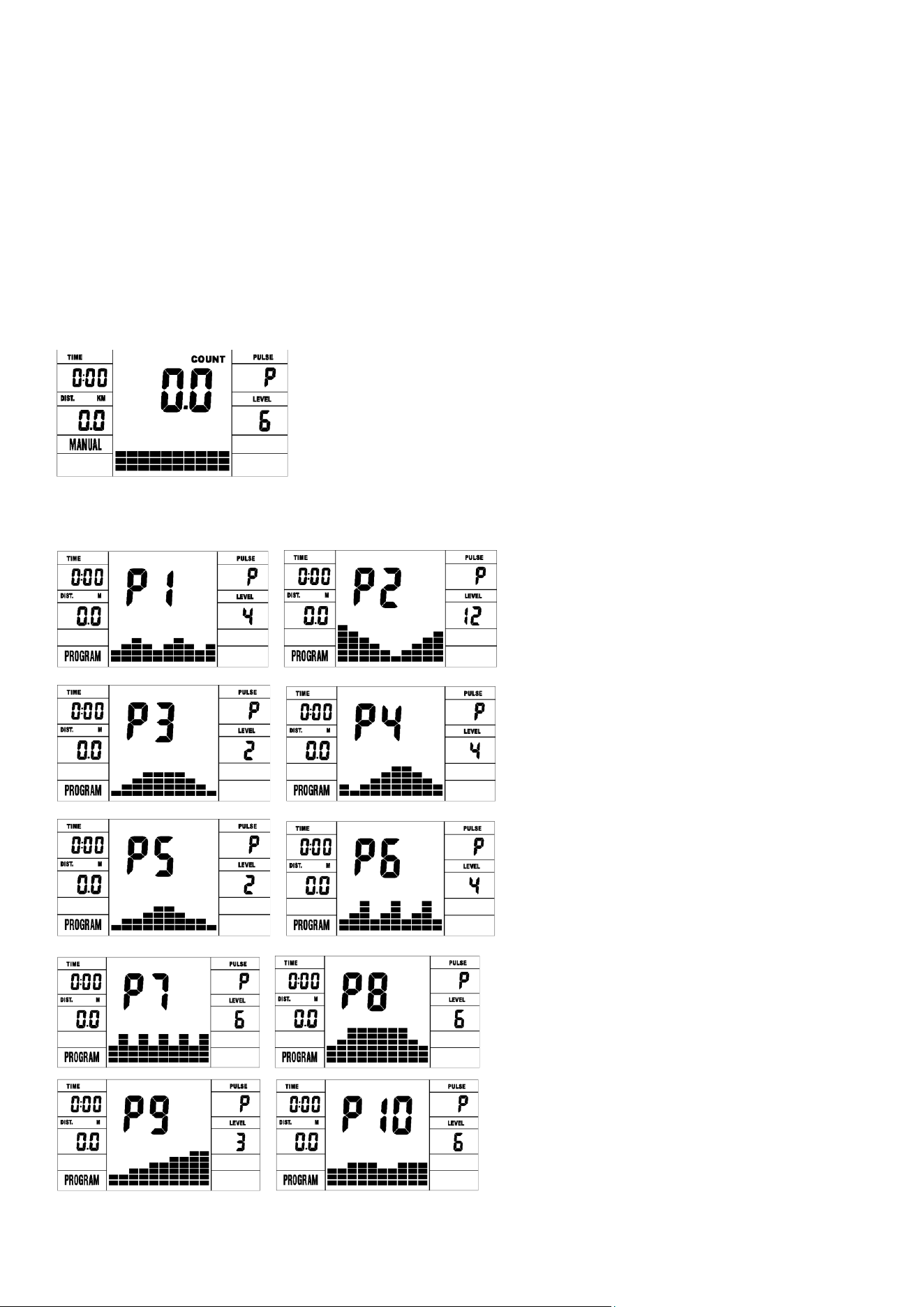
FUNCTION
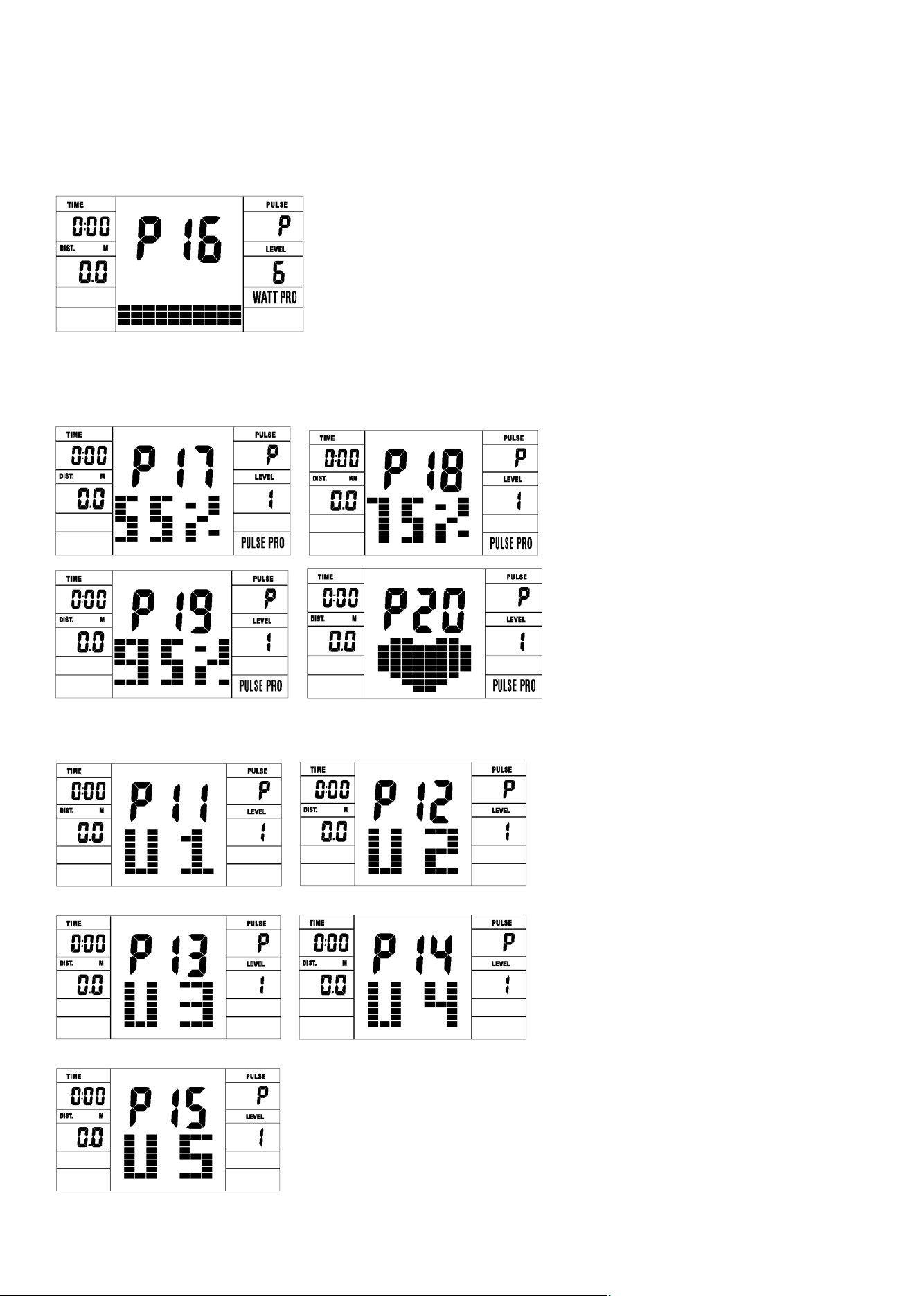
1. Program: 21 programs as following
A: 1 Manual Program
B: 10 Preset Program Profile (PROGRAM: P1-P10)
VII. MOTORIZED COMPUTER
OPERATION MANUAL
16 | OPERATION MANUAL
P1: ROLLING P2:VALLEY P3: FATBURN P4:RAMP P5:MOUNTAIN
P6: INTERVAL P7:CARDIO P8:ENDURANCE P9:SLOPE P10:RALLY
C: 1 Watt Control Program (WATT PRO: P16)
D: 4 Heart Rate Control Program: (PULSE PRO: P17-P20) 55%H.R, 75%H.R, 95%H.R
and TARGET H.R
E: 5 User Setting Programs: CUSTOM1 to CUSTOM5 (P11 ~ P15)

17
1. Record the user’s data of 5 User Setting Programs.
2. Display Speed (RPM), TIME and WATT., CAL and DIST, at the same time.
3. The computer will turn off automatically if there is no operation, speed signal and pulse signal over
4 minutes. Meanwhile, it will store your current exercise data and urn the loading resistance to the
minimum. Once you press any button or in motion, the computer will turn on automatically.
4. There are 10 columns of loading bars , and 8 bars in each column. Each column represents 1 minutes
workout (without the change of TIME value), and each bar represent 2 levels of loading.
• In "stop" mode, press ENTER button to enter into program selection and setting value which flash in
related window.
A: When you choose the program, press Enter to confirm the one you like.
B: When in setting, press ENTER to confirm the value that you would like to preset.
• During the start mode, press ENTER to choose display the speed or RPM, or switch automatically.
• Press START/STOP button to start or stop the programs.
• During any mode, hold down this button for 2 seconds to totally reset the computer.
• In stop mode and the dot matrix character flash, press this button to select the program up. If the
related window value flash, press this button to increase the value.
• During the start mode, press this button to increase the training resistance.
BUTTONS
1. ENTER:
2. START/STOP:
3. UP:
OPERATION MANUAL |

18 | OPERATION MANUAL
• In stop mode and the dot matrix character flash, press this button to select the program down. If the
related window value flash, press this button to decrease the value.
• During the start mode, press this button to decrease the training resistance.
1. To press or rotate of UP, DOWN button should be followed by different model.
2. It is suggested to cover your finger within the marked region to select functions in case of any wrong
action.
1. Turn on the computer. Plug in one end of the adaptor to the AC electrical source and connect the other
end to the computer.
The computer will beep and enter into initial mode.
2. Program select and value setting
A. Press UP, DOWN button to select the program that you like.
B. Press ENTER button to confirm the selected program and enter time setting window.
C. The time will flash, and then press UP, DOWN button to set up your desired time. Press ENTER to
confirm the value.
D. The distance will flash, and then press UP, DOWN button to set up the desired distance value. Press
ENTER to confirm the value.
E. The calories will flash, and then press UP, DOWN to set up the desired calories to be consumed. Press
ENTER to confirm the value.
F. Press START/ STOP to begin exercise.
• First test your current heart rate and show your heart rate value, press this button to enter into pulse
recovery testing.
• When you are in pulse recovery mode, press this button to exit.
• Manual Program and Preset Program P1-P10
4. DOWN:
5. RECOVERY:
NOTE:
OPERATION
19OPERATION MANUAL |
• Watt Control Program (WATT PRO:P16)
• HEART RATE CONTROL PROGRAM: 55%H.R, 75% H.R and 95% H.R (PULSE PRO: P17-P19)
A. Press UP, DOWN to select the watt control program.
B. Press ENTER to confirm the selected watt control program, and enter into time setting window.
C. The time will flash, and then press UP, DOWN button to set up the desired time,. Press ENTER to
confirm the value.
D. The distance will flash, and then press UP, DOWN button to set up the desired distance value. Press
ENTER to confirm the value.
E. The calories will flash, and then press UP, DOWN button to set up the desired calories to be consumed.
Press ENTER to confirm the value.
F. The watt display will flash, and then press UP, DOWN button to set up the watt to do the exercise.
Press ENTER to confirm the value.
G. Press START/ STOP to begin exercise.
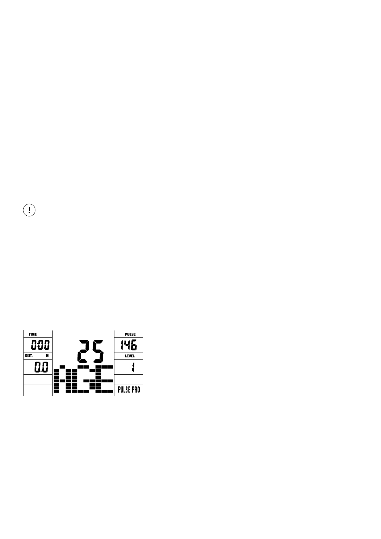
The maximum heart rate depends on different age and this program will ensure you do the healthy
exercise within maximum heart rate.
A. Press UP , DOWN button to choose the heart rate control program.
B. Press ENTER to confirm the heart rate control program, and enter into AGE setting window.
C. The time will flash, and then press UP, DOWN button to set up the desired time. Press ENTER to
confirm the value.
D. The distance will flash, and then press UP, DOWN button to set up the desired distance value. Press
ENTER to confirm the value.
E. The calories will flash, and then press UP, DOWN button to set up the desired calories to be consumed.
Press ENTER to confirm the value.
F. The age will flash, and then press UP, DOWN button to set the user’s age. Press ENTER to confirm the value.
NOTE: The WATT value is decided by the TORQUE and RPM. In this program, the WATT value
will keep at constant value. It means that if you peddle quickly, the load resistance will
decrease and if you peddle slowly, the load resistance will increase to ensure you at the
same watt value.

20| OPERATION MANUAL
G. When the target heart rate control program flash, the computer will display the user’s target heart
rate according to user’s age.
H. Press START/ STOP to begin exercise.
• HEART RATE CONTROL PROGRAM: TARGET HEART RATE (PULSE PRO: P20)
The user can set any target heart rate to do the exercise.
• User Profile Programs: CUSTOM1-CUSTOM5 (P11-P15)
A. Press UP, DOWN button to select TARGET HEART RATE program.
B. Press ENTER to confirm your choice and enter time setting window.
C. The time display will flash, and then press UP, DOWN button to set the desired time to do the exercise.
Press ENTER to confirm the value.
D. The distance will flash, and then press UP, DOWN button to set up the desired distance value. Press
ENTER to confirm the value.
E. The calories will flash, and then press UP, DOWN button to set up the desired calories to be consumed.
Press ENTER to confirm the value.
F. The target heart rate will flash, and then press UP, DOWN button to set up your target heart rate. Press
ENTER to confirm the value.
G. Press START/ STOP to begin exercise.
NOTE: During exercise, the user’s heart rate value depends on resistance level and speed. The heart rate
control program is to ensure your heart rate within the preset value. When the computer detect your
current heart rate is higher than preset, it will decrease the resistance level automatically or you may
slow down exercise. If your current heart rate is lower than preset, it will increase resistance and you
may speed up.
A. Press UP, DOWN button to select the user.
B. Press ENTER to confirm your choice, and enter into time setting window.
C. The time display will flash, and then press UP, DOWN button to set up the desired time to do the
exercise. Press ENTER to confirm the value.
D. The distance will flash, and then press UP, DOWN button to set up the desired distance value. Press
ENTER to confirm the value.
E. The calories will flash, and then press UP, DOWN button to set up the desired calories to be consumed.
Press ENTER to confirm the value.
F. The first resistance level will flash, and then press UP, DOWN button to set the desired load resistance.
Press ENTER to confirm. Then repeat above operation to set the resistance from 2 to 10.
21
G. Press START/ STOP to begin exercise.
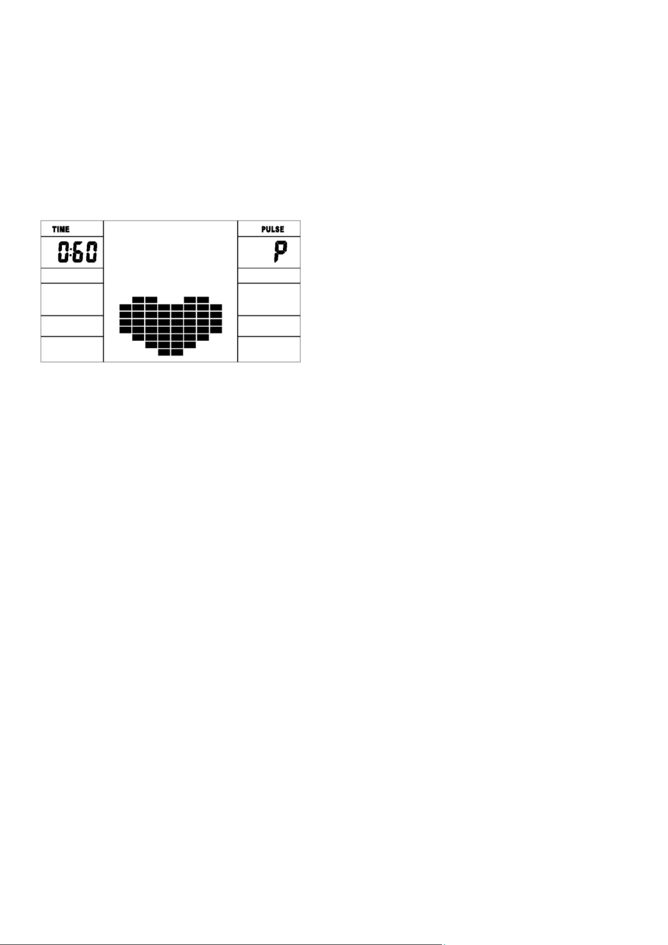
The pulse recovery test is to compare your heart rate before and after exercise. It is target to determine
your heart strength via the measuring. Please do the test as below:
A. Both your hands hold the pulse sensor or via wireless transmitter belt to test the pulse(if applicable),
the computer will display your current pulse value.
B. Press RECOVERY to enter the pulse recovery test and the computer program will enter the stop status.
C. Keep pulse detecting.
D. Time will count down from 60 seconds to 0 second.
E. When time reaches 0, the test result (F1-F6) appears on the display.
F1=Excellent F2=Good F3=Fair F4=below average F5= No Good F6= Poor
F. If the computer does not detect your current heart rate first, pressing RECOVERY will not enter into
pulse recovery test. During the pulse recovery test, press RECOVERY to exit the test and return to the
stop status.
3. Pulse Measurement
Please place both your palms on the contact pads and the computer will show your current heart beat
rate in beats per minute (BPM) on the LCD after 3~4 seconds. During the measurement, heart icon will
flash with simulative ECG showing.
Remark: During the process of pulse measurement, because of the contact jamming, the measurement
value may not be stable when start, then it will return to normal level. The measurement value cannot
be regarded as the basis of medical treatment.
NOTE: If the computer is also equipped with wireless heart rate measuring via the transmitter belt, and
with hand pulse function, the hand-measurement-signal-detecting is preferred.

22
Speed KM/H(M/H): showing your current speed. Range: 0.0-99.9 KM/H(M/H).
RPM: showing the current rotate per minute. Range : 0-999.
TIME: the accumulative exercise time, range : 0:00-99M59S.
the preset time range is 5:00-99M00S. The computer will start to count down from preset time to 0:00
with average time for each resistance level. When it reaches to zero, the program will stop and computer
alarm. If you do not preset the time, it will run with one minute decrement each resistance level.
DIST: the exercise accumulative distance. Range : 0.0-99.9-999KM(MILE) the preset distance range :1.0-
99.0-999. When the distance reaches 0, the program will stop and the computer will alarm.
CALORIE: he exercise accumulative calories burnt. Range : 0.0-99.9-999 the preset calories range :10.0-
90.0-990. When the calorie reaches 0, the program will stop and the computer will alarm.
PULSE: showing the exercise heart rate value.
Range: 60-240BPM(beat per minute)
Colorful screen: Computer dormancy after, light and screen put out together.
RESISTANCE LEVEL: showing level. Range:1-16
WATT: show the exercise watt, the interval should be 10,between 30-350.
BLUETOOTH & APP: Download the App and connect with Bluetooth.
ADAPTOR
INPUT: AC 230-240V
OUTPUT: 8VDC 500MA
SPECIFICATIONS
23
VIII. EXERCISE GUIDE
PLEASE NOTE:
Before beginning any exercise program, consult your physician. This is important especially if you are
over the age of 45 or individuals with pre-existing health problems.
The pulse sensors are not medical devices. Various factors, including the user’s movement, may
affect the accuracy of heart rate readings. The pulse sensors are intended only as an exercise aid in
determining heart rate trends in general.
Exercising is great way to control your weight, improving your fitness and reduce the effect of aging and
stress. The key to success is to make exercise a regular and enjoyable part of your everyday life.
The condition of your heart and lungs and how efficient they are in delivering oxygen via your blood to
your muscles is an important factor to your fitness. Your muscles use this oxygen to provide enough
energy for daily activity. This is called aerobic activity. When you are fit, your heart will not have to work
so hard. It will pump a lot fewer times per minute, reducing the wear and tear of your heart.
So as you can see, the fitter you are, the healthier and greater you will feel.
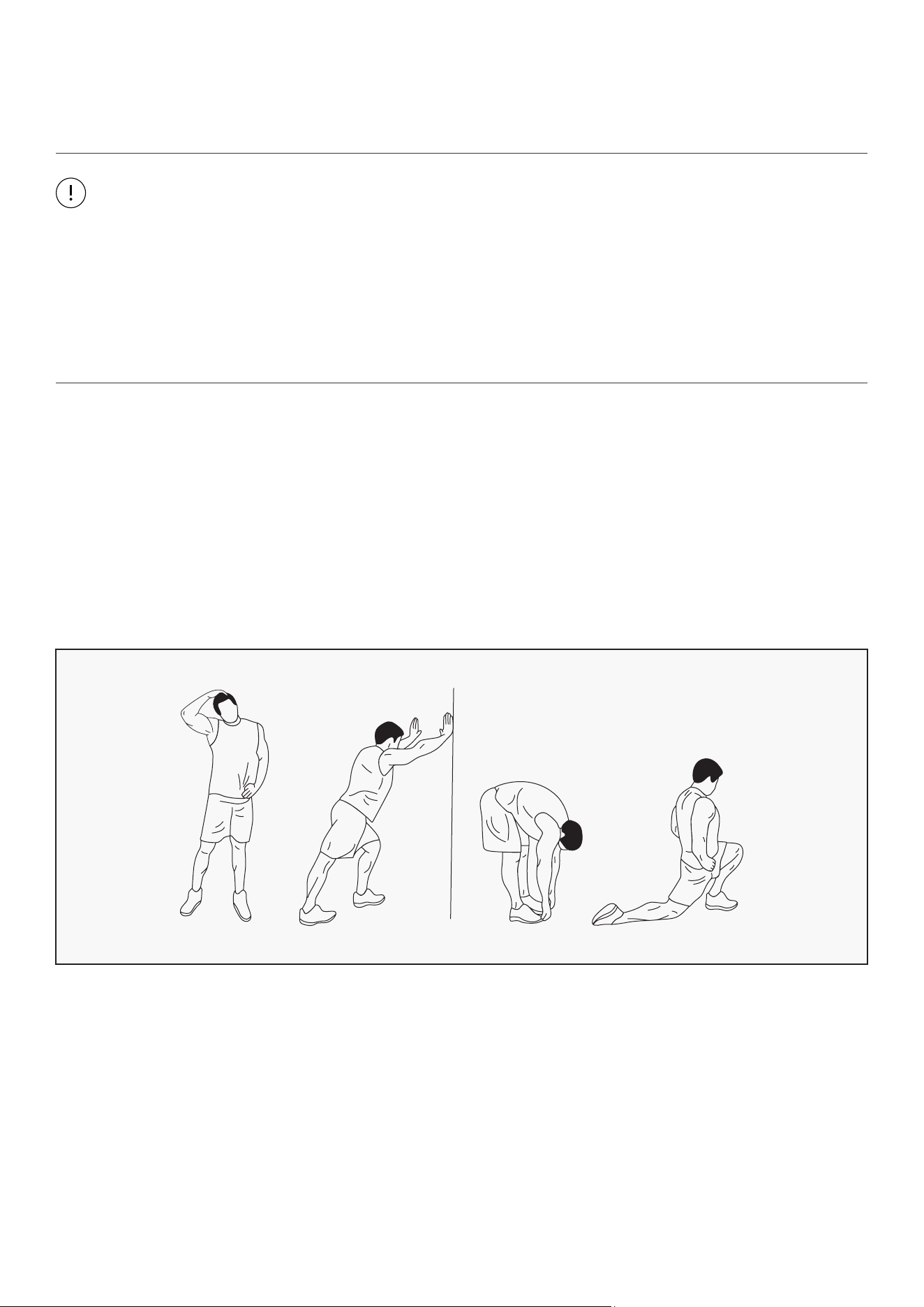
WARM UP
Start each workout with 5 to 10 minutes of stretching and some light exercises. A proper warm-up
increases your body temperature, heart rate and circulation in preparation for exercise. Ease into your
exercise.
After warming up, increase the intensity to your desired exercise program. Be sure to maintain your
intensity for maximum performance. Breathe regularly and deeply as you exercise.
EXERCISE GUIDE |
24
COOL DOWN
Finish each workout with a light jog or walk for at least 1 minute. Then complete 5 to 10 minutes of
stretching to cool down. This will increase the flexibility of your muscles and will help prevent post-
exercise problems.
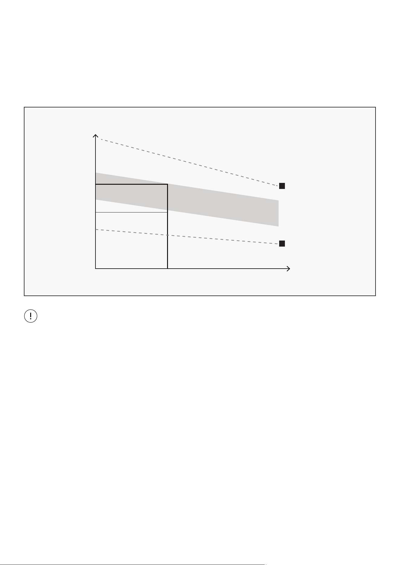
WORKOUT GUIDELINES
This is how your pulse should behave during general fitness exercise. Remember to warm up and
cool down for a few minutes.
TARGET ZONE
MAXIMUM
85%
70%
COOL DOWN
AGE
HEART RATE
200
180
160
140
120
100
80
20 25 30 35 40 45 50 55 60 65 70 75
| EXERCISE GUIDE

25
IX. WARRANTY
AUSTRALIAN CONSUMER LAW
Many of our products come with a guarantee or warranty from the manufacturer. In addition, they come
with guarantees that cannot be excluded under the Australian Consumer Law. You are entitled to a
replacement or refund for a major failure and compensation for any other reasonably foreseeable loss
or damage.
You are entitled to have the goods repaired or replaced if the goods fail to be of acceptable quality and
the failure does not amount to a major failure. Full details of your consumer rights may be found at
www.consumerlaw.gov.au.
Please visit our website to view our full warranty terms and conditions:
http://www.lifespanfitness.com.au/warranty-repairs
WARRANTY AND SUPPORT
Any claim against this warranty must be made through your original place of purchase.
Proof of purchase is required before a warranty claim may be processed.
If you have purchased this product from the Official Lifespan Fitness website, please visit
https://lifespanfitness.com.au/warranty-form
For support outside of warranty, if you wish to purchase replacement parts or request a repair or
service, please visit https://lifespanfitness.com.au/warranty-form and fill in our Repair/Service
Request Form or Parts Purchase Form.
Scan this QR code with your device to go to lifespanfitness.com.au/warranty-form
WARRANTY |


WWW.LIFESPANFITNESS.COM.AU