X-02
Cross Trainer
USER MANUAL
NOTE:
Product may vary slightly from the item pictured due to model upgrades. This manual may be subject to updates or changes.
Up to date manuals are available through our website at www.lifespanfitness.com.au
Read all instructions carefully before using this product.
Retain this owner’s manual for future reference.
IMPORTANT
All nuts and bolts are to be checked and tightened on a regular basis. This includes pedals and
other moving parts. Failure to do so may cause damage to your threads and void your warranty.

2
TABLE OF
CONTENTS
I. Important Safety Instructions . . . . . . . . . . . . . . . . . . . . . . . . . . . . . . . 03
II. Care Instructions . . . . . . . . . . . . . . . . . . . . . . . . . . . . . . . . . . . . . . . . . . . . . 04
III. Parts List . . . . . . . . . . . . . . . . . . . . . . . . . . . . . . . . . . . . . . . . . . . . . . . . . . . . 05
IV. Exploded Diagram . . . . . . . . . . . . . . . . . . . . . . . . . . . . . . . . . . . . . . . . . . . 07
V. Assembly Instructions . . . . . . . . . . . . . . . . . . . . . . . . . . . . . . . . . . . . . . . 08
VI. Tension Adjustment . . . . . . . . . . . . . . . . . . . . . . . . . . . . . . . . . . . . . . . . . 14
VII. Display Manual . . . . . . . . . . . . . . . . . . . . . . . . . . . . . . . . . . . . . . . . . . . . . . . 15
VIII. Warranty . . . . . . . . . . . . . . . . . . . . . . . . . . . . . . . . . . . . . . . . . . . . . . . . . . . . . 17
IX. Hand Pulse Technology . . . . . . . . . . . . . . . . . . . . . . . . . . . . . . . . . . . . . . . . 18
| TABLE OF CONTENTS

3
I. IMPORTANT SAFETY
INSTRUCTIONS
WARNING: Read all instructions before using this machine.
It is important your machine receives regular maintenance to prolong its useful life. Failing to
regularly maintain your machine may void your warranty.
Please retain this manual properly for future reference.
• It is important to read this entire manual before assembling and using the equipment. Safe and
effective use can only be achieved if the equipment is assembled, maintained and used properly.
PLEASE NOTE: It is your responsibility to ensure that all users of the equipment are informed of all
warnings and precautions
• Before starting any exercise program you should consult your doctor to determine if you have any
medical or physical conditions that could put your health and safety at risk, or prevent you from
using the equipment properly. Your doctor’s advice is essential if you are taking medication that
affects your heart rate, blood pressure or cholesterol level.
• Be aware of your body’s signals. Incorrect or excessive exercise can damage your health. Stop
exercising if you experience any of the following symptoms: pain, tightness in your chest, irregular
heartbeat, and extreme shortness of breath, lightheadedness, dizziness or feelings of nausea. If you
do experience any of these symptoms, you should consult your doctor before continuing with your
exercise program.
• Keep children and pets away from the equipment. This equipment is designed for adult use only.
• Use the equipment on a solid, flat level surface with a protective cover for your floor or carpet.
To ensure safety, the equipment should have at least 2 meters of free space around it.
• Before using the equipment, check that the nuts and bolts are securely tightened. If you hear any
unusual noises coming from the equipment during use and assembly, stop immediately. Do not use
the equipment until the problem has been rectified.
• Wear suitable clothing while using the equipment. Avoid wearing loose clothing that may get caught
in the equipment or that may restrict or prevent movement.
• This equipment is designed for indoor and family use only.
• Care must be taken when lifting or moving the equipment so as not to injure your back.
IMPORTANT SAFETY INSTRUCTIONS |
4
• Always keep this instruction manual and assembly tools at hand for reference.
• The equipment is not suitable for therapeutic use.
• The pulse or heart rate sensors are not medical devices. Various factors, including the user’s
movement, may affect the accuracy of heart rate readings. The pulse sensors are intended only as
exercise aids in determining heart rate trends in general.
II. CARE INSTRUCTIONS
• Lubricate moving joints with grease after periods of usage.
• Be careful not to damage plastic or metal parts of the machine with heavy or sharp objects.
• The machine can be kept clean by wiping it down using dry cloth.
• All nuts and bolts are to be checked and tightened on a regular basis. This includes pedals and other
moving parts. Failure to do so may cause damage to your thread and void your warranty.
| CARE INSTRUCTIONS
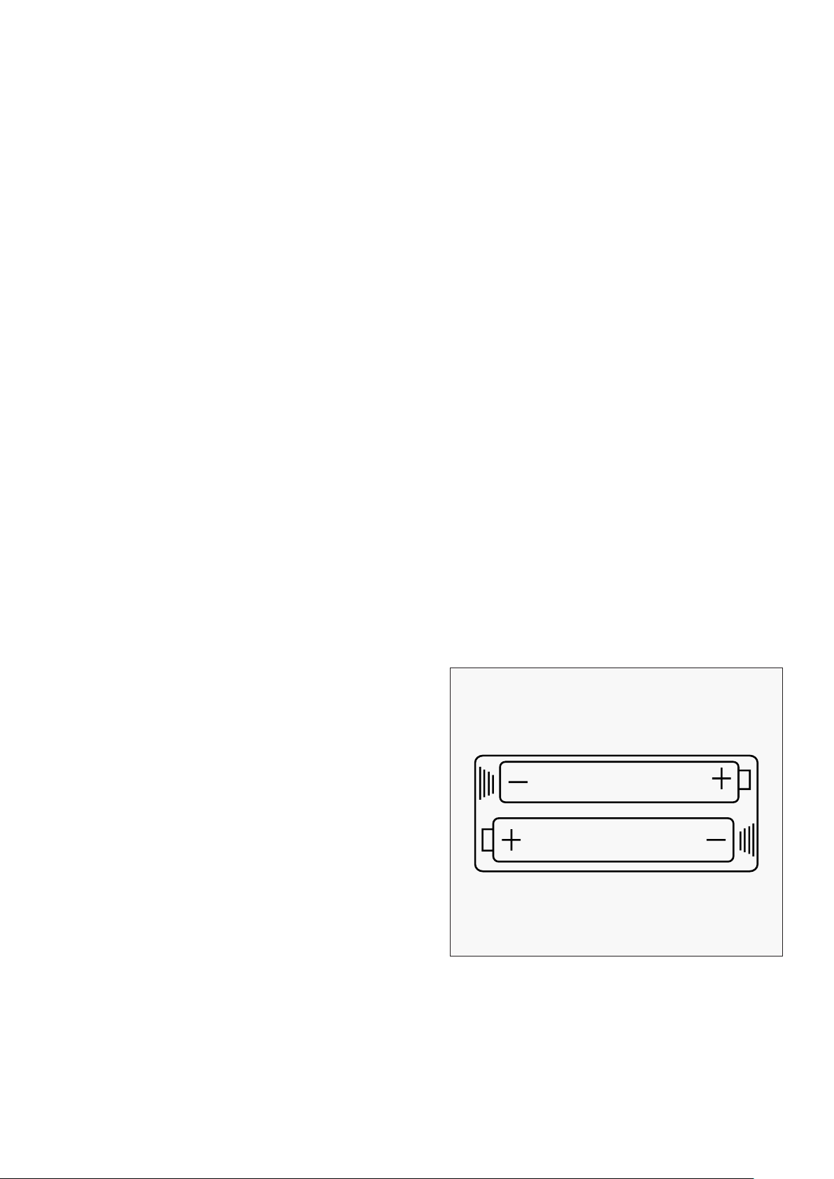
• Batteries are to be installed or replaced by adult only.
• Do not use rechargeable batteries. Do not mix
different battery types. Do not mix old and new
batteries. Do not mix alkaline, standard (Carbon-
Zinc), or rechargeable (Nickel-Cadmium) batteries.
• Remove batteries when product is not in use.
• Remove exhausted batteries from product and
dispose of in accordance with the
manufacturer’s recommendation.
• Do not attempt to recharge non-rechargeable
batteries.
• Batteries are to be inserted with correct polarity.
• The supply terminals are not to be short-circuited.
• Do not dispose of batteries in fire, batteries may
explode or leak.
BATTERY USAGE

5PARTS LIST |
NO. Name Qty
1
Main Frame 1
2
Front stabilizer 1
3
Rear stabilizer 1
4L/R
Swing bar 1pr.
5
Arc washer 4
Φ10x1.5xΦ25xR28
6L/R
Pedal tube 1pr.
7L/R
Handle bar 1pr.
8L/R Chain cover
1pr.
9
Fan wheel 1
10
Small plastic cover 1
11L/R
Pedal 1pr.
12 Long axle 1
13
End cap 4
14 Foam grip 2
15 End cap 10
16 Plastic bushing 4
17 knob 4
18 Transport wheel 2
19 Alloy bushing 10
20
Alloy bushing
4
21
Bushing
2
22
Fan wheel axle
1
23
Hex thin nut M10x1xB5
4
24
Adjusting bolt Φ16x1xΦ28
1
25
Flange nut M10x1xB10xΦ20
2
NO. Name Qty
26
Sensor
1
27
Crank
1
28
Connecting tube
2
29
Washer
1
30
2-Slot nut
1
31
Collar ball
2
32 Collar housing 2
33
Hex nut 2
34
Chain 1
35
Tension belt 1
36
Tension controller 1
37 Extension wire 1
38 Cross taping screw ST4.8x20 2
39 Cross taping screw ST4.8x18 3
40 Cross screw ST4.8x20 1
41 Flat washer D8x3xΦ38 2
42 Adjusting bolt 2
43 Hex bolt M8x20 2
44 Hex bolt M10x45xL20 4
45
Nylon nut M10
6
46
Carriage bolt M10xL57xL20
4
47
Acorn nut M10
4
48L/R
Nylon nut B0.5x20
1pr.
49
Fixed bar
1
50
Computer
1
51
Spring washer Φ13B2
2
III. PARTS LIST

6 | PARTS LIST
NO. Name Qty
52
Adjusting washer 2
Φ10.5x3xΦ18
53
Hex bolt M8x2x145 2
54
Cross taping screw ST4.8x40 4
55
Washer 1
56
D shape washer
2
Φ28xΦ16.2x14xB5
57
Allen bolt M10x18 2
58 Pulse sensor wire
2
59
Hex bolt M6xL45xL12 2
60
Nylon nut M6 2
61
Hex bolt M10xL55xL25 2
62L/R
Pedal hinge bolt 1pr.
63
Plastic cap S17 4
64
Cross screw 2
65
Saddle 1
66 Flat washer D8 3
67 Nylon nut M8 3
68 Saddle post 1
69 Decorative sleeve 1
70
Tri-knob
1
NO. Name Qty
71
Cap
6
72
Chain wheel
1
73
Handlebar post
1
74
Flat washer
2
75
Nylon nut M8
2
76
Arc washer
4
d8x1.5xΦ19xR13
77
Plastic cap S19
2
78
3-Slot Nut
1
79
Pulse extension wire
2
80
Cap
2
81 Dumbbell bracket 2
82
Cross screw M6x16 4
83
Dumbbell 2lbs 2
84
Dumbbell 3lbs 2
85
Connect chips 2
86 Rope 2
87 Flat washer D8xΦ16x1.5 2
88 Allen bolt M8x16 2
89 Cap 2
7EXPLODED DIAGRAM |
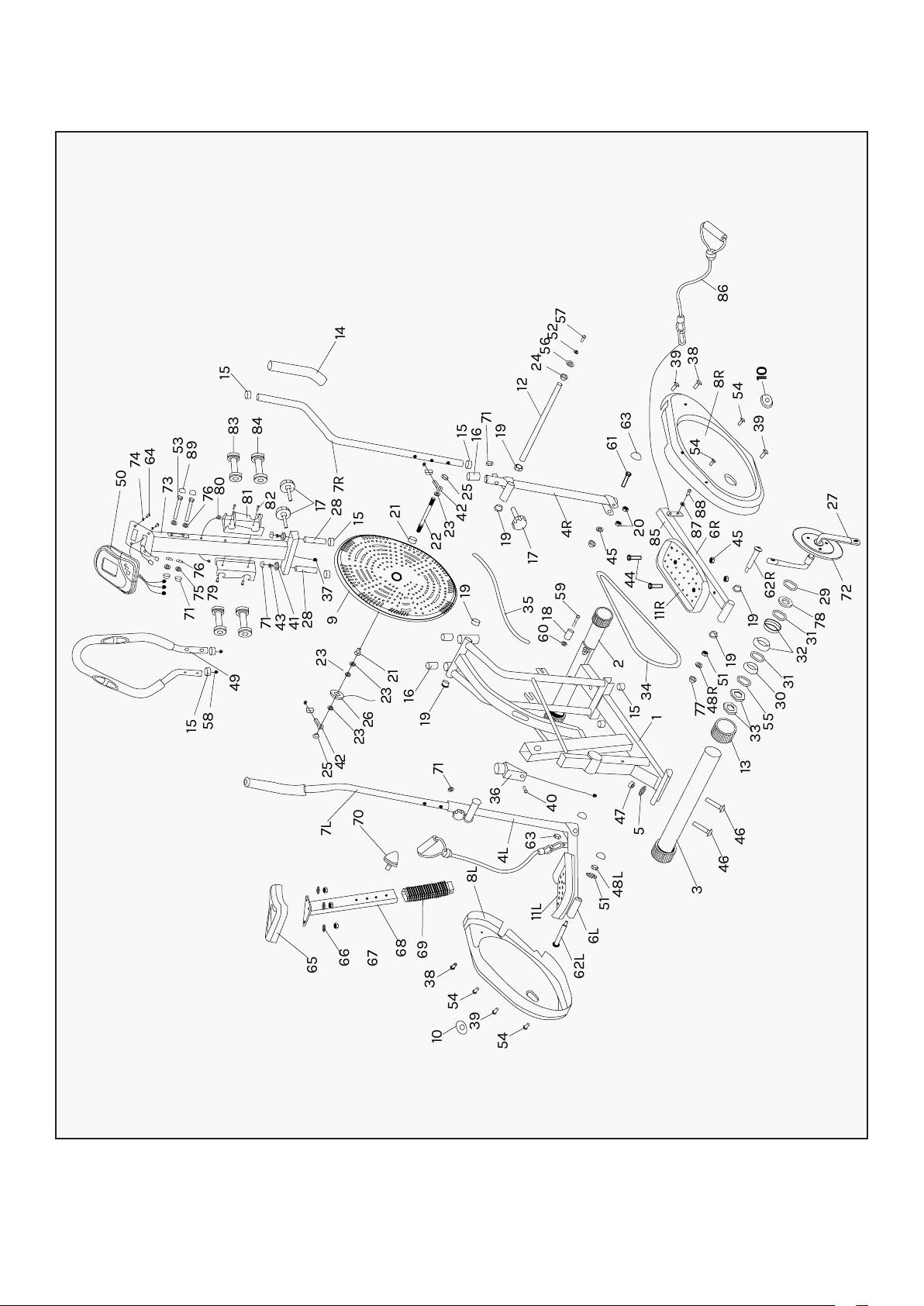
IV. EXPLODED DIAGRAM
15
71
71
43
41
28
37
9
23
25
42
23
23
21
16
19
71
70
7L
66
67
68
69
38
54
10
39
54
62L
6L
11L
63
4L
36
40
48L
47
5
3
46
46
1
15
2
34
77
13
33
55
30
31
32
31
78
29
72
27
45
6R
87
88
85
20
45
44
11R
59
18
60
48R
51
19
19
62R
51
8L
65
26
15
21
22
23
42
25
15
16
71
19
19
35
19
17
4R
28
17
81
80
76
53
73
64
74
50
89
82
83
15
14
84
7R
75
76
79
58
49
12
61
63
39
38
8R
54
54
39
10
10
86
24
56
52
57
8 | ASSEMBLY INSTRUCTIONS
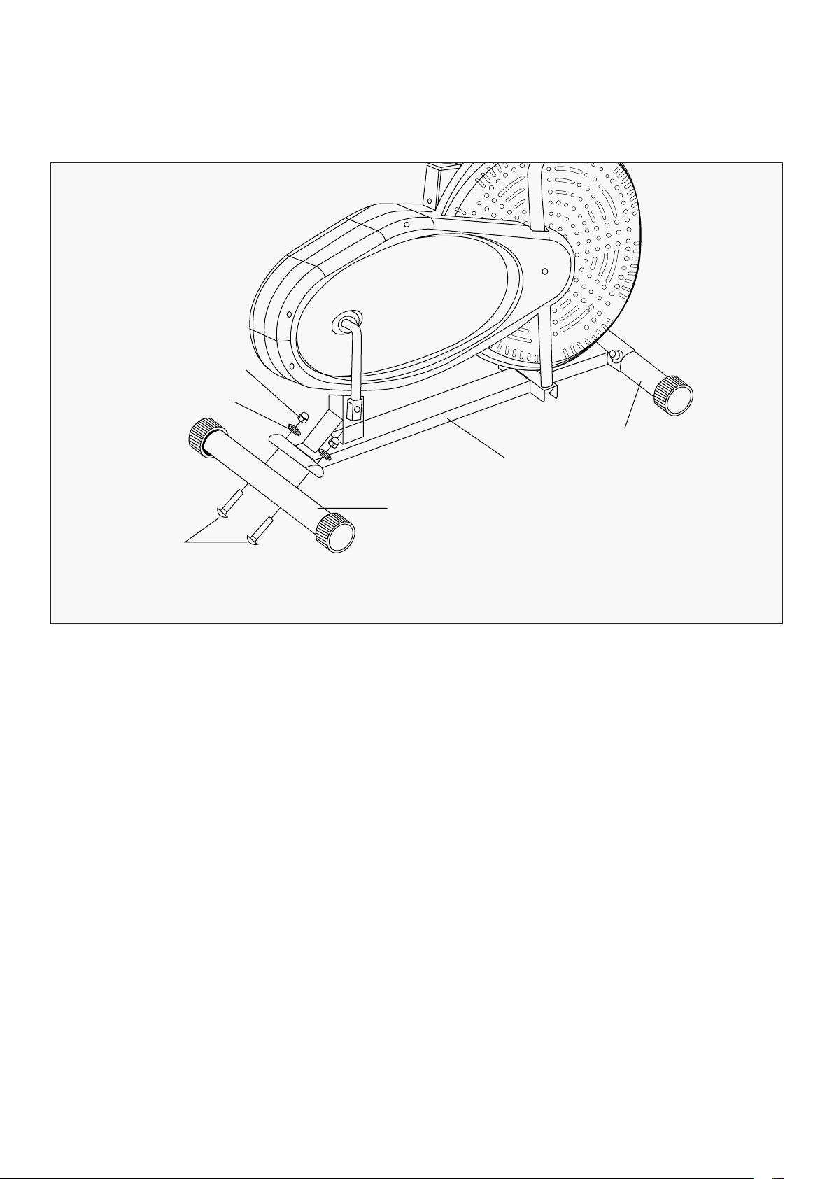
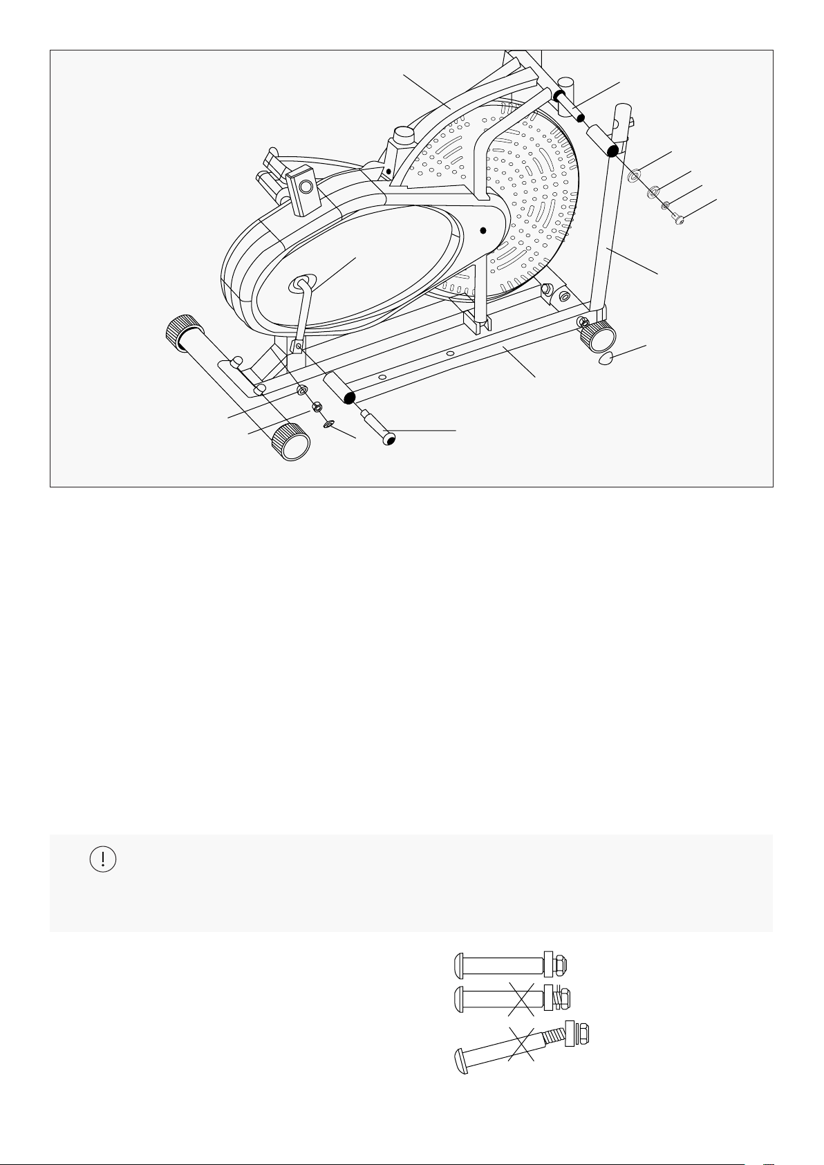
1. Attach the Stabilizer (3) onto the Main frame (1), secure with the Carriage bolts (46),
Arc washers (5), and Acorn nuts (47). Repeat the steps for the second stabilizer (2)
V. ASSEMBLY INSTRUCTIONS
Install the Stabilizers
STEP 1
47
5
46
3
1
2
9ASSEMBLY INSTRUCTIONS |
STEP 2
1. Remove Adjusting bolt (24), D shape washer (56), Spring washer (52) and Bolts (57) from the
Handle bar shaft (12) on one side.
2. Mount one Coupler bar (4R) to the Main section, then attach the other side’s Coupler bar (4L).
3. Reinstall the Adjusting bolt (24), D shape washer (56), Spring washer (52) and Bolts (57) as shown.
Do not tighten completely yet.
4. Fit the right Pedal arms (6R) to the Crank (27). Secure with the right Pedal hinge bolts (62R),
Spring washers (51) and Nylon nuts (48R).
5. Tighten the Bolts (57), right Pedal hinge bolts (62R) and Nylon nuts (48R). Fit the left Pedal
arms (6L) with the same method.
Note: Both Pedals hinge bolts are labeled L FOR LEFT and R FOR RIGHT. To tighten, turn
the left bolt COUNTERCLOCKWISE and the right bolt CLOCKWISE. Move the Crank to a proper
angle for easy tightening of Bolts.
While you assemble this step, hold the "62L/R"
part as per the diagram below. The examples
marked with X are incorrect. The "62L/R" part
must be horizontal to be correctly screwed
crankshaft.
6. Attach the plastic caps (77, 63).
Install the Coupler bars & Pedal arms
12
27
77
48R
62R
6R
63
4R
57
52
56
24
51
1
10 | ASSEMBLY INSTRUCTIONS
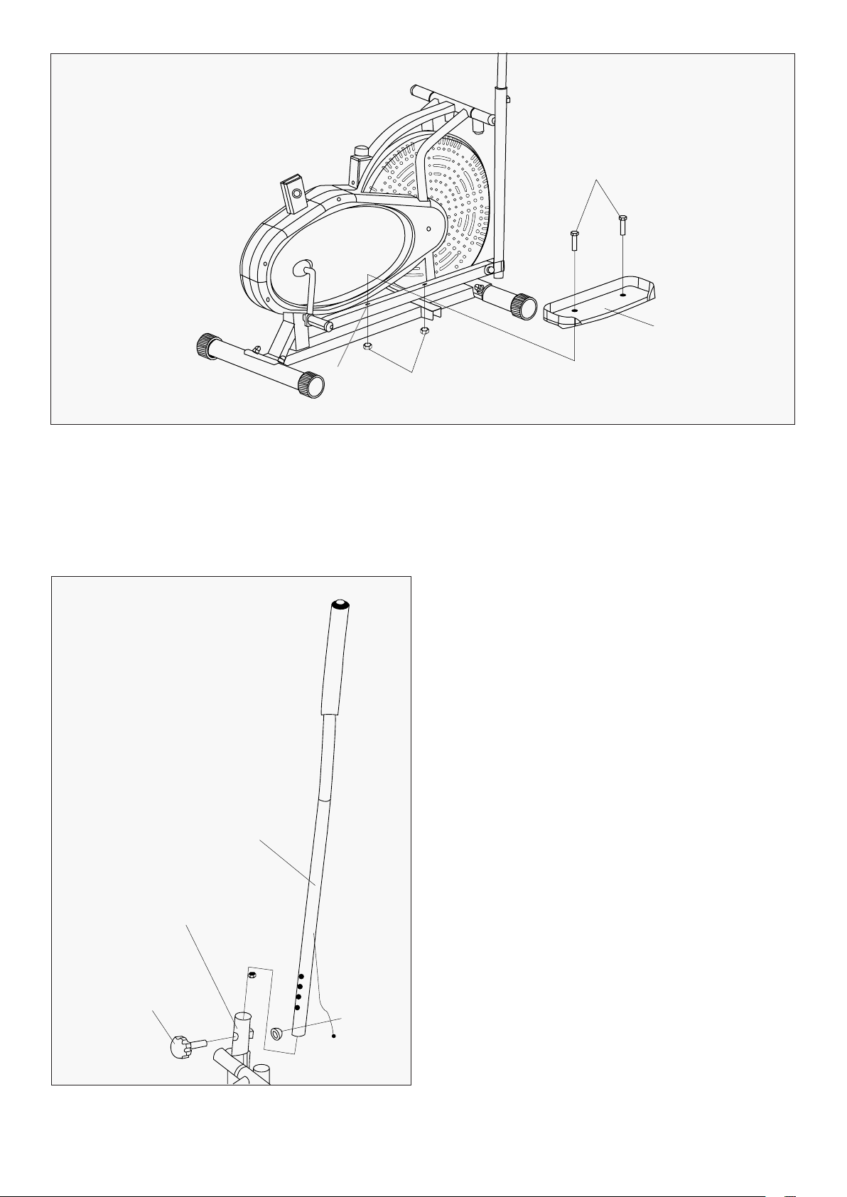
Install the Pedals
Install the Handle bars
1. Attach the Pedals (11 R&L) to the Pedal arms (6 R&L) respectively. Secure in place with
the Hex bolts (44) and Nuts (45).
1. Insert the Handle bars (7L&7R) into the Swing
bars (4L/R) accordingly. Select a comfortable
height for exercise, and make sure both Handle
bars are at a same level.
2. Attach the plastic caps (71).
STEP 3
STEP 4
44
45
6R
11R
7L
4L
17
71
11
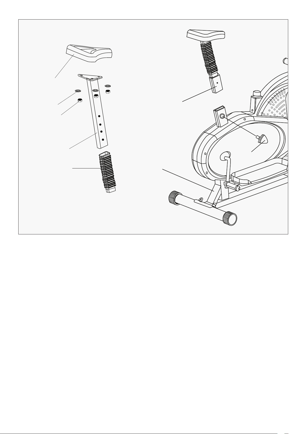
Install the Saddle and Saddle post
1. Place the Saddle (65) over the Saddle post (68). Secure in place with the Flat washers (66)
and Nylon nuts (67).
2. Slide the Decorative Sleeve (69) onto the Saddle post, then insert the Saddle post (68) into
the Main section (1); adjust to a proper position, secure in place with the Tri-knob at the
preferred height level (70).
STEP 5
ASSEMBLY INSTRUCTIONS |
65
66
67
68
68
70
1
69
12
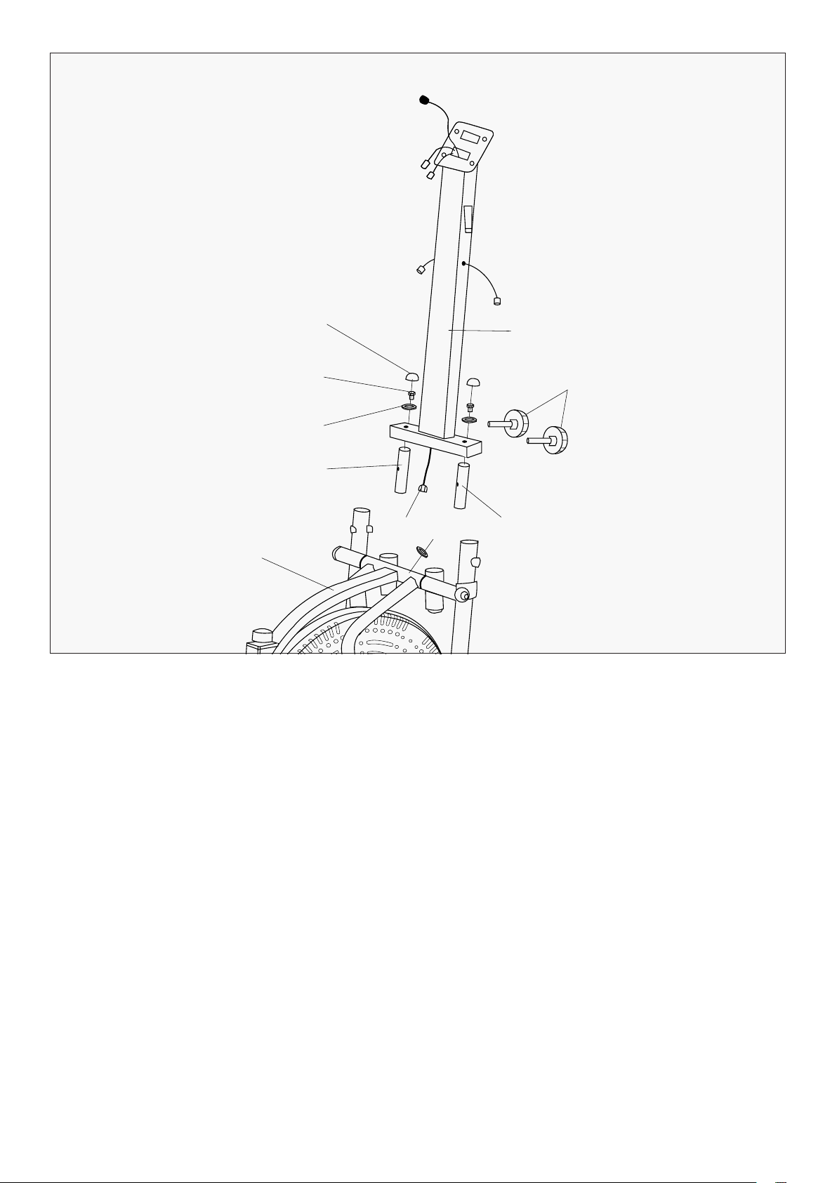
Install the Computer post
1. Insert the Connecting tubes (28) to the Main section (1). Secure in place with Knobs (17).
2. Attach the Computer post (73) onto the Connecting tubes (28). Secure with Flat
washers (41) and Hex bolts (43). Cover the Bolts with Caps (71).
3. Connect the sensor wire (26) and extension wire (37).
4. Check and re-fasten the Knobs (17).
STEP 6
| ASSEMBLY INSTRUCTIONS
73
71
43
41
28
37
26
28
1
17
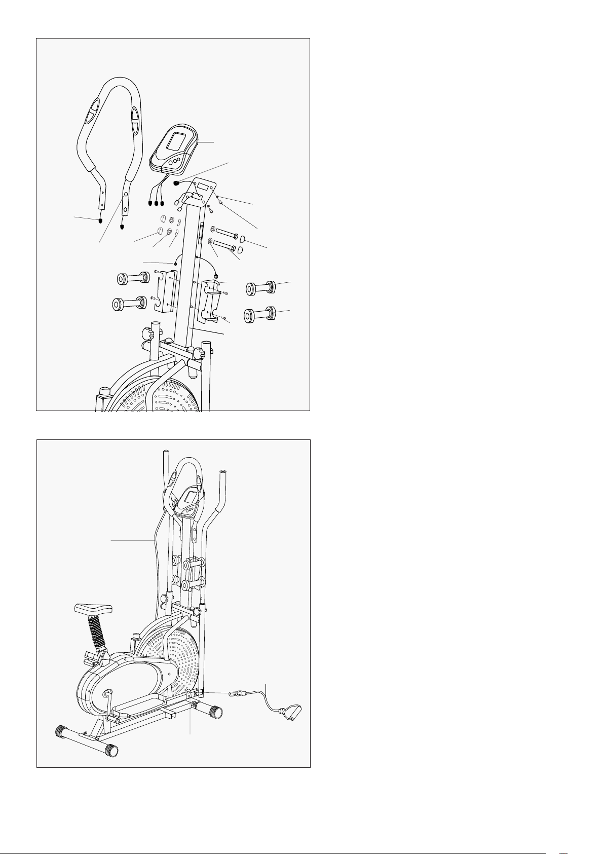
13ASSEMBLY INSTRUCTIONS |
Install the Computer
Attach resistance bands
1. Connect the Pulse sensor Wire (58) and
Pulse extension wire (79). Secure the
Handlebar (49) to the Handlebar post (73)
with the Hex bolt (53), Nylon nut (75) and Arc
washer (76). Cover the Cap (71&89)
2. Connect the Pulse extension wire (79) and
Sensor extension wire (37) with the wires
of computer (50). Attach the Computer (50)
to the bracket with Cross screw (64) and flat
washer (74).
2. Attach the Dumbbell bracket (81) to the
Handlebar post (73) with Cross screw (82).
Place on the Dumbbells (83&84).
1. Buckle the Rope (86) to the Connection
chips (85).
STEP 7
STEP 8
50
37
74
64
89
53
76
81
82
83
84
73
79
7675
71
49
58
86
86
85
14
VI. TENSION ADJUSTMENT
TENSION ADJUSTMENT
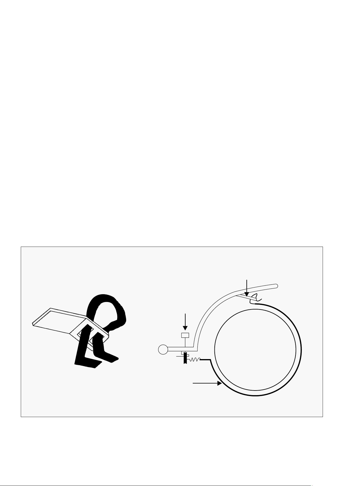
ADJUSTING THE FRICTION BELT
The assembly of your Elliptical Trainer is now complete. As you try your exercises for the first time, you
should adjust the tension to the correct level before you begin your full workout. Turning the adjustment
knob allows you to change the tension level and vary the intensity of your workout as you exercise.
To increase tension turn the tension knob to the clockwise and to decrease tension turn the tension
knob counterclockwise.
You can loosen or tighten the friction belt for greater tension adjustment.
Turn the tension adjustment knob all the way to the loosest setting. Then re-strap the friction belt at the
buckle in the main frame which just beneath the flat beam at the top centre. The more length you allow
for the friction belt to wrap around the fan wheel. the less friction it will cause. Re-adjust the tension
knob after you finished re-strapping.
Friction Belt Buckle
Tension Adjustment
Knob
Friction Belt
The more tightly
the friction belt
wraps around the
fan wheel, the
harder it is for you
to pedal (more
Tension).
| TENSION ADJUSTMENT

15
VII. DISPLAY MANUAL
FUNCTION BUTTONS
FUNCTIONS AND OPERATIONS
MODE
This key lets you to select and lock on to a desired function. Holding down the mode
button will reset all functions to 0.
SET Sets data for "TIME", "DISTANCE", and "CALORIES" when not in scan mode.
RESET
Push down to reset time, distance and calories values to 0. Hold the reset button down
for an extended period of time to reset all values excluding ODO (odometer) to 0.
SCAN
Press the "MODE" button until "SCAN" appears. The monitor will rotate through all of the
following functions: time, speed, distance, calorie, ODO, and pulse. Each function will be
displayed for 4 seconds.
TIME
Counts total time from start to end of workout.
a) TIME COUNT DOWN: Press the "MODE" button until "TIME" appears. Press the "SET"”
button to set your desired exercise time. When the "SET" value reaches is zero, the
computer alarm will sound for 5 seconds.
SPEED Displays current speed
DISTANCE
Counts total distance from start to end of workout
a) DISTANCE COUNT DOWN: Press the "MODE" button until "DIST" appears. Press the
"SET" button to set your desired exercise distance. When the "SET" value reaches is zero,
the computer alarm will sound for 5 seconds.
CALORIES
Counts total calories from start to end of workout.
a) CALORIE COUNT DOWN: Press the "MODE" button until "CAL" appears. Press the "SET"
button to set exercise calories. When the "SET" value reaches is zero, the computer
alarm will sound for 5 seconds.
ODOMETER The total distance which this function is refers to from battery capacity period runs.
PULSE
Press the "MODE" button until "PULSE" appears. Before measuring your pulse rate, place
your palms of your hands on both the contact pads and the monitor will show your
current heart rate in beats per minute (BPM) on the LCD after 6 to 7 seconds. Heart
rate data is an estimate only and should not be used for medical purposes.
AUTO
STANDBY
The computer will enter standby mode if no signal is received for 8 minutes. The
computer will turn on if movement is detected from the flywheel.
DISPLAY MANUAL |

16
SPECIFICATIONS
FUNCTION
Auto Scan Every 4 seconds
Running Time 00:00-99:59
Current speed 0.0~999.9 KM
Trip Distance 0.0~999.9 KM
Total distance(ODO) 0.0~999.9 KM
Calories 0.0~999.9 Kcal
Pulse Rate 40~240BPM
Battery type
2 pcs of size - AA or UM - 3
Operating temperature
0
0
C~+40
0
C
Storage temperature
-10
0
C~+60
0
C
| DISPLAY MANUAL

17
VIII. WARRANTY
WARRANTY |
AUSTRALIAN CONSUMER LAW
Many of our products come with a guarantee or warranty from the manufacturer. In addition, they come
with guarantees that cannot be excluded under the Australian Consumer Law. You are entitled to a
replacement or refund for a major failure and compensation for any other reasonably foreseeable loss
or damage.
You are entitled to have the goods repaired or replaced if the goods fail to be of acceptable quality and
the failure does not amount to a major failure. Full details of your consumer rights may be found at
www.consumerlaw.gov.au.
Please visit our website to view our full warranty terms and conditions:
http://www.lifespanfitness.com.au/warranty-repairs
WARRANTY AND SUPPORT
Any claim against this warranty must be made through your original place of purchase.
Proof of purchase is required before a warranty claim may be processed.
If you have purchased this product from the Official Lifespan Fitness website, please visit
https://lifespanfitness.com.au/warranty-form
For support outside of warranty, if you wish to purchase replacement parts or request a repair or
service, please visit https://lifespanfitness.com.au/warranty-form and fill in our Repair/Service
Request Form or Parts Purchase Form.
Scan this QR code with your device to go to lifespanfitness.com.au/warranty-form

18
IX. HAND PULSE TECHNOLOGY
| HAND PULSE TECHNOLOGY
This product comes equipped with hand pulse sensors which are used to pick up tiny EKG/ECG signals
that run through the body when your heart beats. These electrical EKG/ECG signals are very small and
must be amplified 1000 times to make the signal viable for the computer to display your pulse.
To ensure proper operation:
• The user must maintain good, consistent contact on all four sensors.
• The users skin cannot be too dry or too wet.
Other factors that could affect the reading:
• Change of grip on the sensors (during slow pace walking and up to running).
• Tightening of hand muscles will produce small electrical signal.
• Static electricity charges from the air or from walking on the treadmill.
EKG/ECG Sensors may filter through actual EKG/ECG signals and "Noise" factors that may affect the
reading. This will cause the pulse reading to be delayed and will take longer to update the display as the
heart rate changes. Too much noise will create an incorrect reading. Medical conditions or having no
electrical signal in the hands are other factors that may also affect pulse readings.
These are limitations of hand pulse technology and even the most expensive systems (which can
cost upwards of $3,000) used in hospitals have the same problems. The difference is that a patient
in a hospital is not running on a treadmill. Hand pulse technologies work well on stationary exercise
machines like bikes and even elliptical cross trainers but are not perfect on a treadmill. We offer
treadmills with a wireless heart rate receiver which may be the more accurate option.
To test if your hand pulse sensors are working up to specification, hold them while standing on the
sidestep rails, not walking, and see if the reading is more in line with what you would expect. This will
eliminate the movement and static electricity factors. If your hands are dry, then wet them slightly
(saliva works as a great conductor if this doesn’t bother you).

19

WWW.LIFESPANFITNESS.COM.AU