NOTE: This manual may be subject to updates or changes. Up to date manuals are available through our website at www.lifespanfitness.com.au
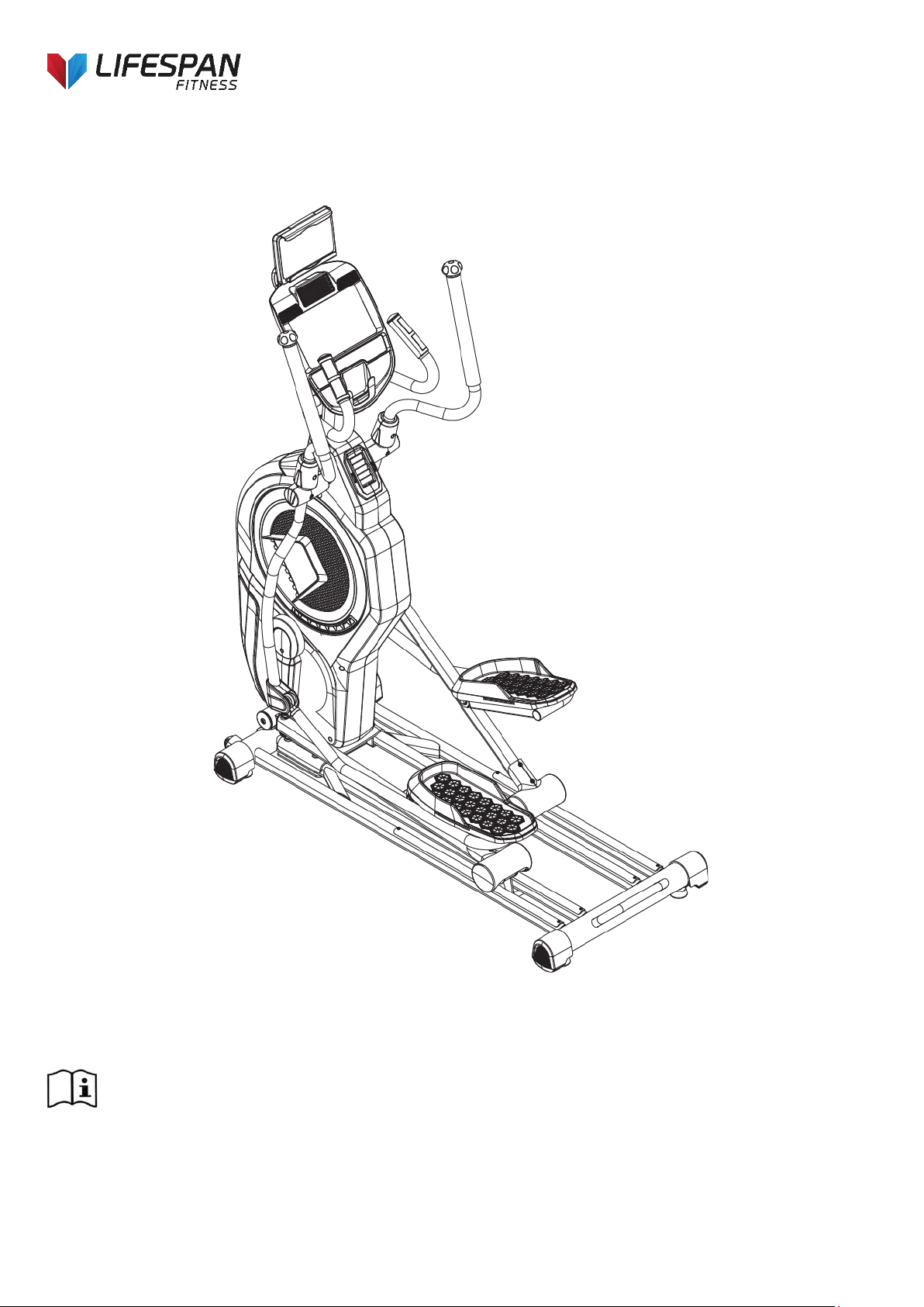
Product may vary slightly from the item pictured due to model upgrades
Read all instructions carefully before using this product. Retain this owner’s manual for future
reference.
XT-44 OWNER’S MANUAL

2
TABLE OF CONTENTS
1. IMPORTANT SAFETY INSTRUCTIONS 3
2. CARE INSTRUCTIONS 4
3. EXPLODED DIAGRAM 5
4. PARTS LIST 7
5. ASSEMBLY INSTRUCTIONS 12
6. COMPUTER OPERATION 15
7. EXERCISE GUIDE 26
8. WARRANTY 28

3
1. IMPORTANT SAFETY INSTRUCTIONS
WARNING - Read all instructions before using this machine.
It is important your machine receives regular maintenance to prolong its useful life. Failing to
regularly maintain your machine may void your warranty.
Please keep this manual with you at all times
1. It is important to read this entire manual before assembling and using the equipment. Safe and
effective use can only be achieved if the equipment is assembled, maintained and used properly.
Please note: It is your responsibility to ensure that all users of the equipment are informed of all
warnings and precautions.
2. Before starting any exercise program you should consult your doctor to determine if you have any
medical or physical conditions that could put your health and safety at risk, or prevent you from using
the equipment properly. Your doctor’s advice is essential if you are taking medication that affects your
heart rate, blood pressure or cholesterol level.
3. Be aware of your body’s signals. Incorrect or excessive exercise can damage your health. Stop
exercising if you experience any of the following symptoms: pain, tightness in your chest, irregular
heartbeat, extreme shortness of breath, lightheadedness, dizziness, or feelings of nausea. If you do
experience any of these symptoms, you should consult your doctor before continuing with your
exercise program.
4. Keep children and pets away from the equipment. This equipment is designed for adult use only.
5. Use the equipment on a solid, flat level surface with a protective cover for your floor or carpet. To
ensure safety, the equipment should have at least 2 meters of free space around it.
6. Before using the equipment, check that the nuts and bolts are securely tightened. If you hear any
unusual noises coming from the equipment during use and assembly, stop immediately. Do not use the
equipment until the problem has been rectified.
7. Wear suitable clothing while using the equipment. Avoid wearing loose clothing that may get caught in
the equipment or that may restrict or prevent movement.

4
8. This equipment is designed for indoor and family use only.
9. Care must be taken when lifting or moving the equipment so as not to injure your back.
10. Always keep this instruction manual and assembly tools at hand for reference.
11. The equipment is not suitable for therapeutic use.
12. The pulse or heart rate sensors are not medical devices. Various factors, including the user’s
movement, may affect the accuracy of heart rate readings. The pulse sensors are intended only as
exercise aids in determining heart rate trends in general.
2. CARE INSTRUCTIONS
a. Lubricate moving joints with grease after periods of usage.
b. Be careful not to damage plastic or metal parts of the machine with heavy or sharp objects.
c. The machine can be kept clean by wiping it down using dry cloth.
d. All nuts and bolts are to be checked and tightened on a regular basis. This includes pedals and other
moving parts.
Failure to do so may cause damage to your thread and void your warranty.
5
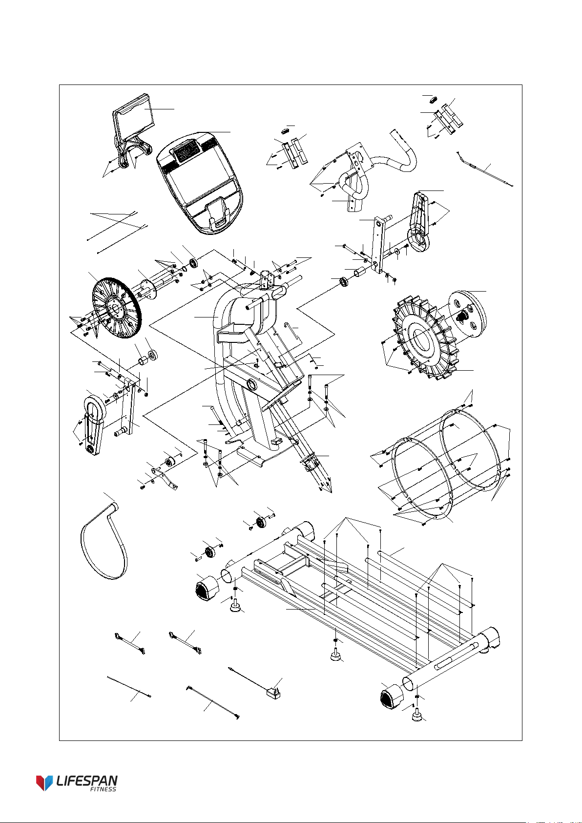
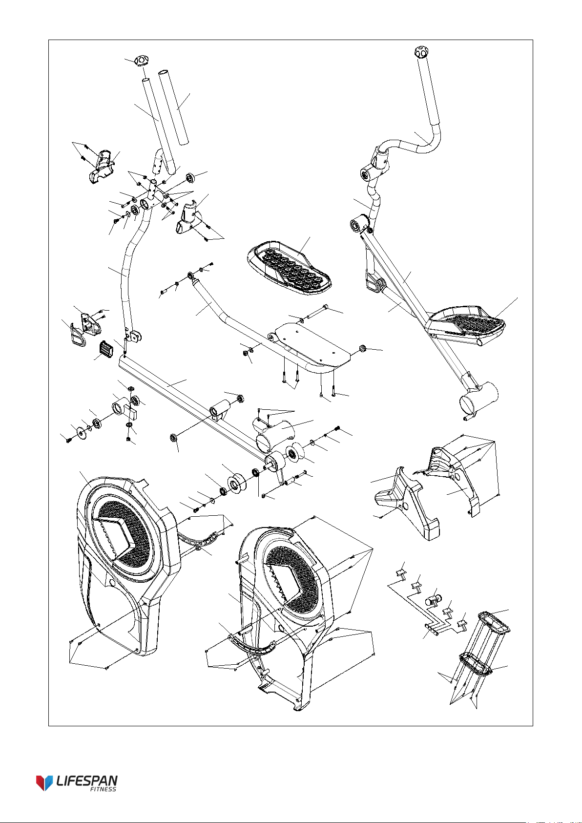
3. EXPLODED DIAGRAM
100
39
62
62
90
77
40
60
98
65
3
60
98
40
77
18
64
68
46
76
48
59
80
48
89
75
12
70
4450
51
68
2
84
43
55
26
52
47
52
47
26
53
33
13
44
68
38
64
18
68
46
76
75
89
68
51
34
87
57
54
80
48
48
59
12
95
52
49
22
62
71
35
66
66
35
71
23
56
62
37
1
56
37
56
37
23
62
94
92
91
93
88
64
64
65
65
65
65
96
65
65
65
65
65
97
25
41
62
86
44
57
99
105
106
42
6
4
6
10
30
19
20
27
28
29
31
44
44
45
45
48
48
50
50
51
51
51
57
57
57
62
62
65
65
67
67
68
68
69
69
70
72
73
73
74
78
78
79
79
85
83
58
82
59
66
81
81
36
5
7
9
11
32
16
17
62
62
14
15
24
24
61
62
63
61
62
21
101
62
61
61
102
102
102
102
103
104
79
110
50
50
57
107
108
79
36
109
109
8

7
4. PARTS LIST
No
.
Description Specification Qty
No
.
Description Specification Qty
1 Basic frame 1 34
Belt pulley
1
2
Main frame
1
35
Wheel
2
3 Console fix frame 1 36 Pulley 4
4
Upper swing arm-left
1
37
Feet pad
5
5 Upper swing arm-right 1 38 Motor belt 1
6 Bottom swing arm-left 1 39 Console 1
7
Bottom swing arm-
right
1 40
Hand pulse top cover
2
8 Pedal group-left 1 41 Magnet sensor fixer 1
9 Pedal group-right 1 42
Sliding rail aluminum
sheet
670×29.5×11.2 4
10
Pedal connection leg-
left
1 43
Flat washer
Φ6×Φ20×t2.0 1
11
Pedal connection leg-
right
1 44 Flat washer Φ8.5×Φ20×t1.5 9
12 Crank 2 45
Flat washer
Φ8.2×Φ25×t2.0 4
13
Tensioning wheel fixer
1
46
Flat washer
Φ32×Φ8.5×t2.0
2
14 Out cover-left 1 47
Flat washer
Φ10×Φ22×2.0 4
15
Out cover-right
1
48
Flat washer
Φ12.5×Φ22×t2.0
8
16 Top cover-left 1 49
Curved washer
Φ10.5×R100×t2.0 2
17 Top cover-right 1 50
Curved washer
Φ8.5×R25×t2.0 11
18 Crank cover 2 51
Spring washer
Φ8 11
19 Handlebar cover 1 2 52
Spring washer
Φ10 6
20
Handlebar cover 2
2
53
Spring washer
Φ10
1
21 Air outlet cover 1 54
Spring washer
Φ25 1
22
Magnet control motor
1
55
Hex Frank head screw
M6
1
23 Stabilizer end cap 4 56
Allen nut
M10 5
24
Out cover decoration
strip
2 57
Hex self-locking nut
M8 16
25
Inside magnet
flywheel
1 58
Pipe plug
Φ32×t2.0
2
26
Allen cylinder head
half thread bolt
M10×70×20 4 59
Hex self-locking nut
M12 4
27
Bottom wing arm
cover-left
2 60
Philips pan head self-
tapping screw
ST3×30 4
28
Bottom wing arm
cover-right
2 61
Philips C.K.S. self-
tapping screw
ST4×10 10
29 Wheel cover 2 62
Philips C.K.S. self-
tapping screw
ST4×16 35
30
Crank axle screw
cover
2 63
Philips C.K.S. self-
tapping screw
ST4×20 4
31 Pedal-left 1 64
Philips C.K.S. full thread
bolt
M5×10 8
32 Pedal-right 1 65
Philips C.K.S. full thread
bolt
M5×15 33
33
Tensioning wheel
1
66
Allen pan head full
thread bolt
M6×12 4

8
No. Description Specification
Qt
y
No. Description Specification Qty
67
Allen Pan head half
thread bolt
M6×50×20 6 93
Power
communication wire
L-400mm 1
68
Allen Pan head full
thread bolt
M8×20 12 94 Power adapter 1
69
Allen Pan head half
thread bolt
M8×40×20 6 95
Allen cylinder head
half thread bolt
M10×90×20 2
70
Allen Pan head half
thread bolt
M8×60×20 4 96
Fly wheel weight
stack
6
71
Allen C.K.S. hollow
bolt
Φ8×33×M6×15 2 97 Fly wheel Φ450×62 1
72
Allen C.K.S. hollow
screw
Φ9.4×23.5-
M6/M6×12
2 98
Hand pulse bottom
cover
2
73
Allen column head
full thread bolt
M8×15 4 99 Crank cover 1 Φ30.5×29.1 1
74
Pedal axis
Φ17×105×M12×15 2 100 I-Pad holder 1
75
Allen full thread bolt
M6×20
2
101
Air outlet bottom
cover
1
76 Flat key 8×10×18 2 102 Hinge 4
77 Round end cap
BLF82/Φ39×Φ30×2
7.5
2 103 Sliding wheel hinge 1
78
Deep groove ball
bearing
6201-ZZ 4 104 Hinge fix plate 1
79
Deep groove ball
bearing
6004-ZZ 8 105 Crank cover 3 Φ45×14.3 1
80
Deep groove ball
bearing
6005-ZZ 2 106 Crank cover 2 Φ30.5×43.5 1
81 bushing E12 /Φ16×Φ12×6.3 4 107
Pedal supporter
bushing
2
82 Tube cap Φ32×t1.5 2 108 Allen C.K.S. screw M8×75 2
83 Foam Φ30×t3.0×350 2 109
Deep groove ball
bearing
R10-ZZ 8
84 Hook 103×Φ26×M6×50 1 110
Pedal supporter
bushing set
2
85
Roll wheel position
stopper
Φ17×Φ8.5×47 2
86 Brake wire L-450×Φ5×Φ1.2×M5 1
87 Crank axle group Φ25×220 1
88 Communication Wire L-1300mm 1
89
Allen half thread bolt
M12×75×20
2
90
Hand pulse
communication wire
L-650mm 2
91 Magnet sensor L-300mm 1
92
MP3communication
wire
L-400mm 1

9
Assembly Parts List
No. Description Specification Qty No. Description Specification Qty
1 Basic frame 1 44 Flat washer Φ8.5×Φ20×t1.5 9
2 Main frame 1 45
Flat washer
Φ8.2×Φ25×t2.0 4
3 Console fix frame 1 47
Flat washer
Φ10×Φ22×2.0 4
4
Upper swing arm-
left
1 49
Curved washer
Φ10.5×R100×t2.0 2
5
Upper swing arm-
right
1 50
Curved washer
Φ8.5×R25×t2.0 7
6
Bottom swing arm-
left
1 51
Spring washer
Φ8 3
7
Bottom swing arm-
right
1 52
Spring washer
Φ10 6
8 Pedal group-left 1 57 Hex self-locking nut M8 10
9 Pedal group-right 1 62
Philips C.K.S. self-tapping
screw
ST4×16 10
10
Pedal connection
leg-left
1 65
Philips C.K.S. full thread
bolt
M5×15 12
11
Pedal connection
leg-right
1 68
Allen Pan head full thread
bolt
M8×20 5
16 Top cover-left 1 69
Allen Pan head half thread
bolt
M8×40×20 6
17 Top cover-right 1 70
Allen Pan head half thread
bolt
M8×60×20 4
19 Handlebar cover 1 2 72 Allen C.K.S. hollow screw Φ9.4×23.5-M6/M6×12 2
20 Handlebar cover 2 2 85 Roll wheel position stopper 2
21 Air outlet cover 1 88 Communication Wire L-1300mm 1
26
Allen cylinder head
half thread bolt
M10×70×20 4 90
Hand pulse communication
wire
L-650mm 2
27
Bottom wing arm
cover-left
2 95
Allen cylinder head half
thread bolt
M10×90×20 2
28
Bottom wing arm
cover-right
2 100 I-Pad holder 1
30
Crank axle screw
cover
2 62
Philips C.K.S. self-tapping
screw
ST4×16(optional) 4
39 Console 1
10
Product Instruction
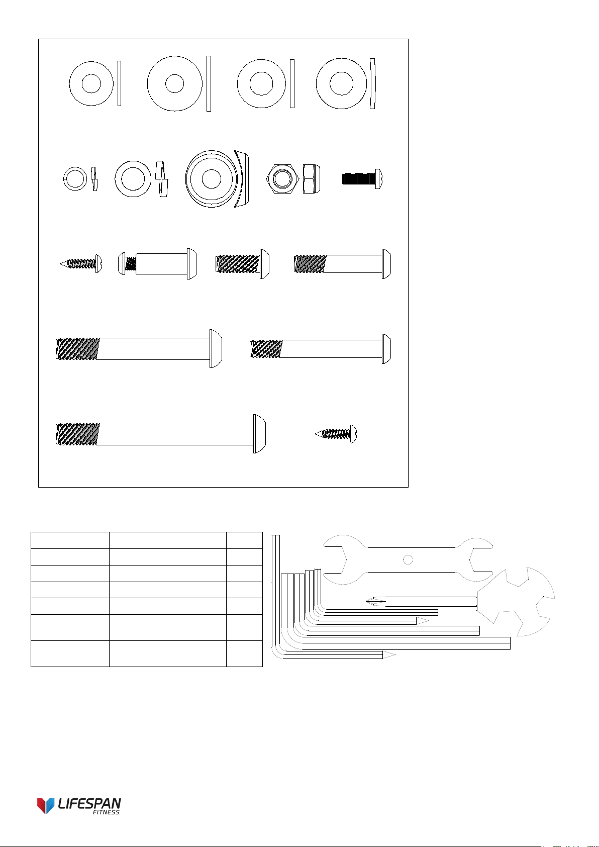
Hardware Pack List
No.
Description
Specification
Qty
No.
Description
Specification
Qty
26
Allen cylinder
head half thread
bolt
M10×70×20 4 62
Philips C.K.S. self-
tapping screw
ST4×16 10
44 Flat washer Φ8.5×Φ20×t1.5 4 65
Philips C.K.S. full
thread bolt
M5×15 12
45 Flat washer Φ8.2×Φ25×t2.0 4 68
Allen Pan head full
thread bolt
M8×20 5
47 Flat washer Φ10×Φ22×2.0 4 69
Allen Pan head half
thread bolt
M8×40×20 6
49 Curved washer
Φ10.5×R100×t2.
0
2 70
Allen Pan head half
thread bolt
M8×60×20 4
50 Curved washer Φ8.5×R25×t2.0 7 72
Allen C.K.S. hollow
screw
Φ9.4×23.5-
M6/M6×12
2
51
Spring washer
Φ8 3 95
Allen cylinder head
half thread bolt
M10×90×20 2
52
Spring washer
Φ10 6 62
Philips C.K.S. self-
tapping screw
ST4×16(optional) 4
57
Hex self-locking
nut
M8 10
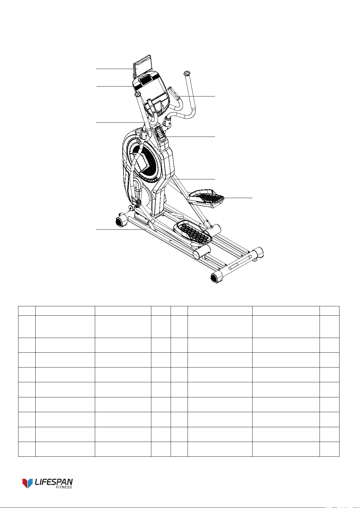
Console
I-Pad holder
Upper swing arm
Handlebar
Air Outlet
Pedal support
Pedal
Basic frame
11
Ø
8.5×
Ø
20
×t1.5-4
Ø
8.2×
Ø
25
×t2.0-4
Ø
10×
Ø
22
×t2.0-4
Ø
8-3
Ø
10-6
Ø
8.5×R25
×t2.0-7
M8-10
M8×20-5
Ø
10.5×R100
×t2.0-2
M5×15-12
iPad Holder Optional
Accessories ST4×16-4
M8×40×20-6
M10×70×20-4 M8×60×20-4
M10×90×20-2
Ø
9.4×23.5-M6-2
ST4×16-10
Tool Kit List:
Description
Specification
Qty
L Wrench
4×30×80
1
L Wrench
5×80×80S
1
L Wrench
5×35×85S
1
L Wrench
6×40×120
1
Phillips Open
Wrench
14×17×75 1
Open end
Wrench
15#&17# 1
12
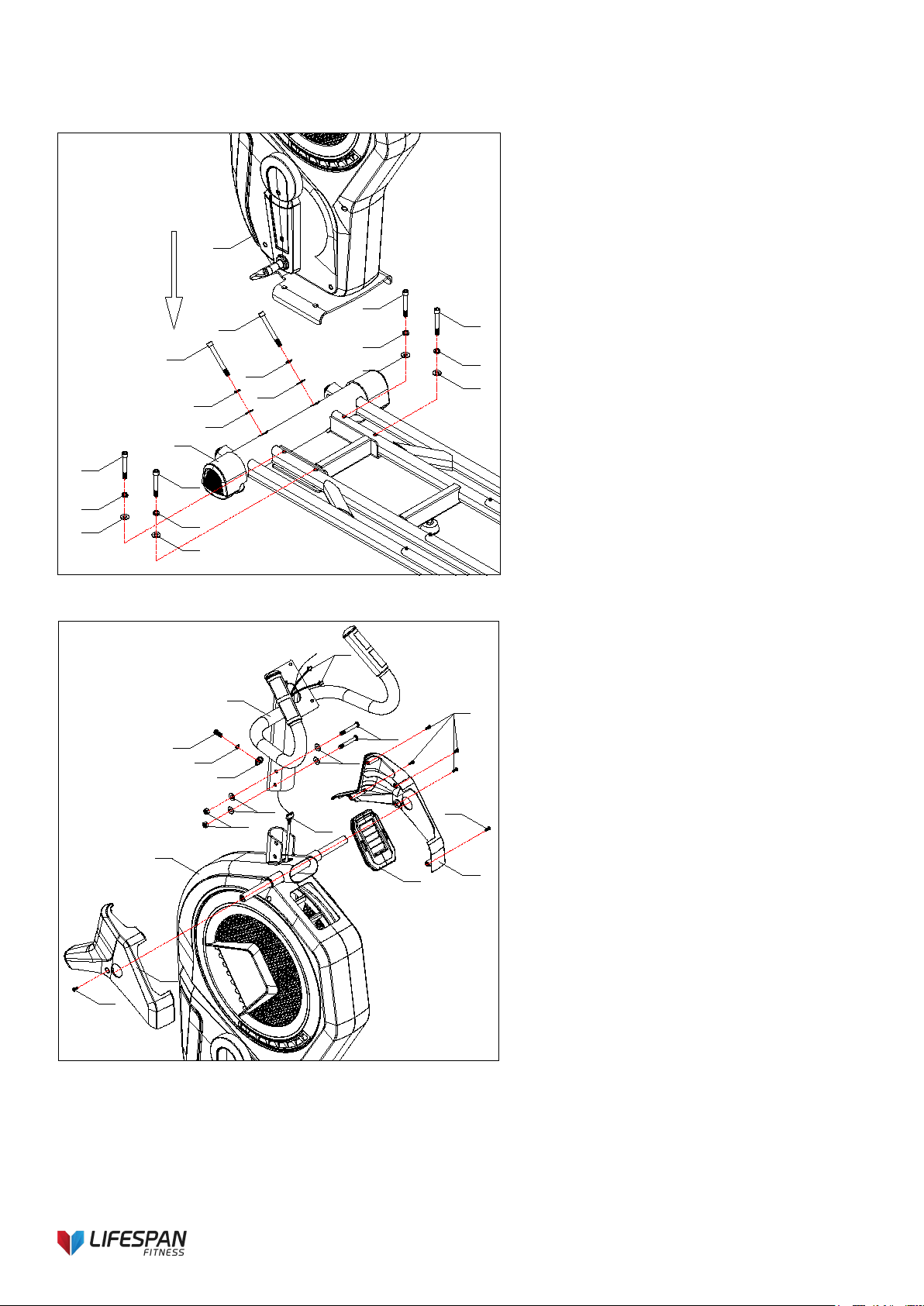
5. ASSEMBLY INSTRUCTIONS
1
95
52
49
95
52
49
26
52
47
26
52
47
26
52
47
26
52
47
1
2
2
62
62
16
16
17
62
70
44
44
57
3
50
51
68
88
2
90
Step 1
1. Place the main frame (2) on the basic
frame (1), secure with 2pcs Allen
cylinder head half thread screw (95),
2pcs spring washer (52), 2pcs curved
washer (49) and 4pcs Allen cylinder
head half thread screw (26), 4pcs
spring washer (52), 4pcs flat washer
(47).
Step 2
1. Pull out the communication line (88) from
the hole of console fix group (3).
2. Assemble console fix group (3) on the
main frame (2), secure with 1pc curved
washer (50), 1pc spring washer (51), 1pc
Allen pan head full thread bolt (68), and
4pcs flat washer (44), 2pc hex self-locking
nut (57), 2pcs Allen pan head half thread
bolt (70).
3. Attach left top cover (16), right top cover
(17) and air outlet cover (21), secure with
6pcs Philips C.K.S. self-tapping screw
(62).
Attention: After connected the communication line,
insert all lines into upright post, to avoid clamping
the lines.
Please put all the bolts and washers on the frame
holes first, then secure them.
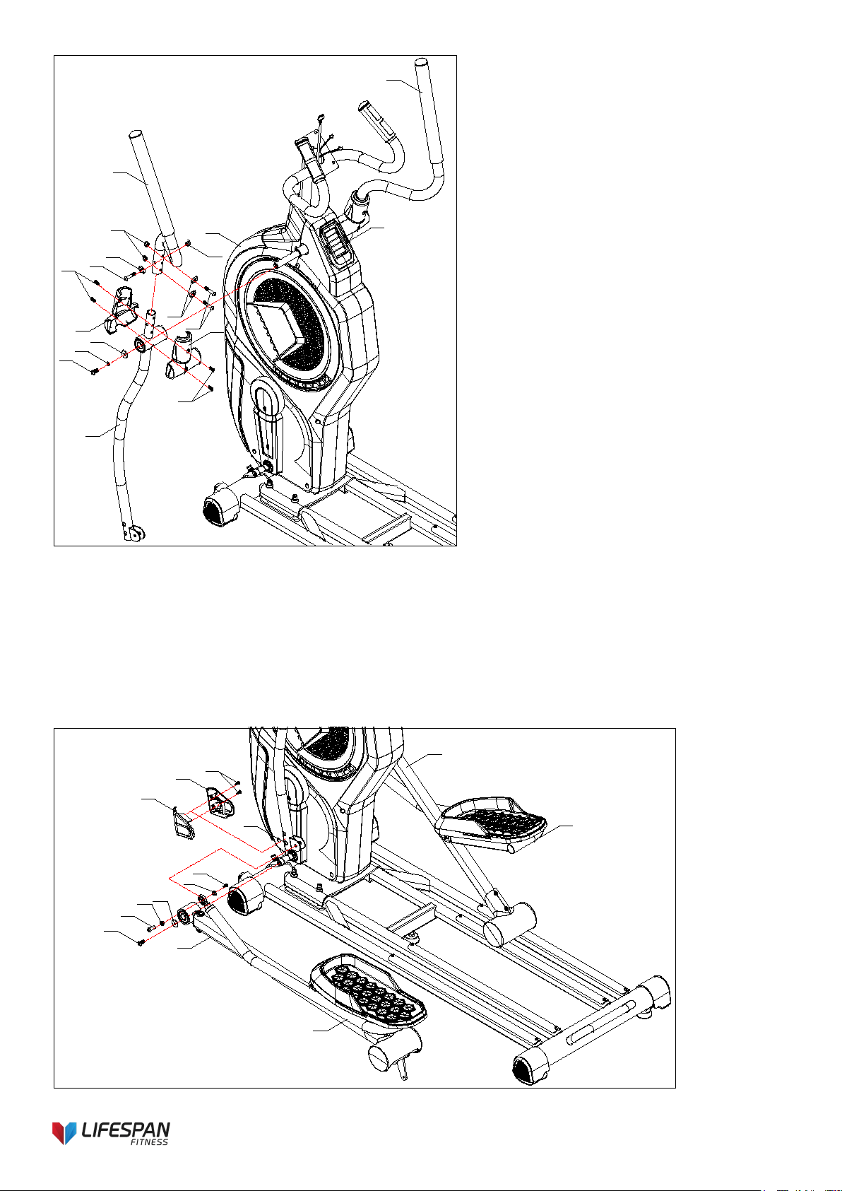
13
45
51
68
50
69
65
57
57
3
20
19
69
50
65
4
5
6
7
2
28
72
8
10
72
45
68
62
9
11
27
4
6
81
81
Step 3
1. Add some oil to the axle of the main
frame. Assemble the bottom swing
arm (6) on the main body, secure
with 1pc Allen pan head full thread
bolt (68), 1 pc spring washer (51)
and 1pc flat washer (45).
2. Assemble the top swing arm L (4) on
the bottom swing arm R (6), secure
with 3pcs Allen pan head full thread
bolt (69), 3pcs curved washer (50)
and 3pcs hex self-locking nut (57).
3. Secure the handlebar cover 1 (19)
and handlebar cover (20) at the
top/bottom wing arm connection by
4pcs Philips C.K.S. full thread bolt
(65)
4. Assemble the right side same as
above steps.
Step 4
1. Add some oil to the axle of the main frame. Place the pedal group left (8) on the track, secure the
pedal group left (8) by 1pc flat washer (45), 1pc crank axle screw cover (30) and 1pc Allen pan head
full thread bolt (68) on the axle.
2. Apply some of the grease to the axle of the Allen C.K.S. hollow screw (72). Connect left pedal
connection leg (10) with bottom wing arm (6), secure with 1pc Allen C.K.S. hollow screw (72).
3. Attached left bottom swing arm cover (27) and right bottom swing arm cover (28) on the left swing
arm (6), secure with 2pcs Philips C.K.S. self-tapping screw (62).
5. Assemble the right side same as above steps.
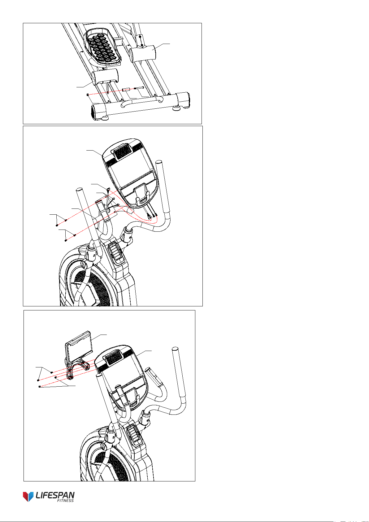
14
5
8
9
85
70
57
39
3
6
65
65
88
90
Step 5
1. Install the Roll wheel position stopper
(85) on Pedal group-left (8) with an Allen
Pan head half thread bolt (70) and a hex
self-locking nut (57)
2. Assemble the right side same as the
above steps.
3. Add some oil on the sliding rail.
Step 6
1. Connect the communication line (88),
and hand pulse communication line (90)
with console communication line.
2. Assemble the console (39) on console fix
frame (3), and secure with 4pcs Philips
C.K.S. full thread bolt (65).
Step 7
1. Attach the I-pad holder (100) to the
console (39) with 4pcs Philips C.K.S.
self-tapping screw (62).
Attention: If you buy an I-pad holder, the
step is needed. Otherwise, you can skip
this step.
7
39
100
62
62
15
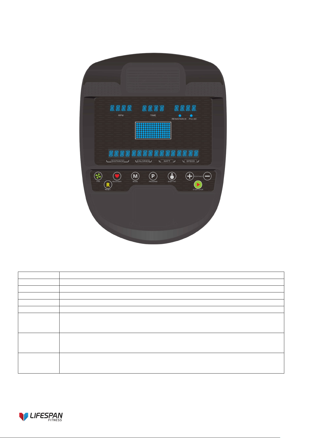
6. COMPUTER OPERATION
Console Operation Instruction
BUTTON FUNCTIONS
RECOVERY
- To test heart rate recovery status.
MODE
- In STOP mode, press this button to select function or confirm all setting values.
PROGRAM
- To select workout program.
BODY FAT
- To test the Body Fat% (5.0%~ 50%) and BMI (0~50).
+
- To adjust upward resistance level, select program or increase function value.
-
- To adjust downward resistance level, select program or decrease function value.
RESET
- In STOP mode or setting mode, press it to reverse to main menu.
- Hold down this key for 2 seconds and console will reboot and start from user
- profile setting mode.
START/STOP
- To start or stop training.
- When user stop training by pressing START/STOP key, the computer will
- remain all the setting values.
FAN
(
optional)
- When power-on or during workout, user can press FAN button to start fan
- function. Press it again to turn it off.

16
DISPLAY FUNCTION
TIME
- Count up – no preset target, time will count up from 0:00.
- Count down – with preset target, time will count down from preset to 0, then
- system STOP. And system alarm 8s with 4 sounds in every second.
- Display range: 0:00 99:59; Setting range: 0:00~99:00
SPEED
- In START mode, with sensor input, screen display training speed in 3s;
- Without sensor input for 4.6s, the SPEED value is 0.
- Display range: 0.0 ~ maximum 99.9 KM/H or ML/H.
- SPEED & RPM value will display by turn in every 6s.
RPM
- In START mode, with sensor input, screen display training rotation per minute
in 3s; Without sensor input for 4.6s, the RPM value is 0.
- Display range: 0 ~ maximum 999.
- SPEED & RPM value will display by turn in every 6s..
CALORIES
- Count up – no preset target, calories will count up from 0.0.
- Count down – with preset target, calories will count down from preset to 0,
then system STOP. And system alarm 8s with 4 sounds in every second.
- Display range: 0~999CAL; Setting range: 0~990CAL
DISTANCE
- Count up – no preset target, distance will count up from 0.0.
- Count down – with preset target, distance will count down from preset to 0,
- then system STOP. And system alarm 8s with 4 sounds in every second.
- Display range: 0.0~99.9km(ml); Setting range: 0.0~99.0km (ml)
PULSE
- With pulse signal input, it will display user heart rate in 7.5s; without pulse
- input, PULSE window display 0 in 6s.
- When pulse exceeds the preset Target value, console will remind with Bi-bi
sound.
- -Display range: 0-30~230; Setting range: 0-30~230
WATT
- Display power consumption during training. With sensor input, it will display
- WATT value in 3s; without any signal input, WATT window display 0 in 4.6s.
- Display range: 0~999.
MANUAL
- Manually adjust workout load level.
PROGRAM
- Self-select load level to workout; 12 profiles preset to be selected (P1~P12).
USER
- User create his own resistance level profile to workout.
H.R.C.
- Target HR training mode.
- Four modes for selection: 55%, 75%, 90%, TAG.
WATT
CONSTANT
- WATT constant training mode.
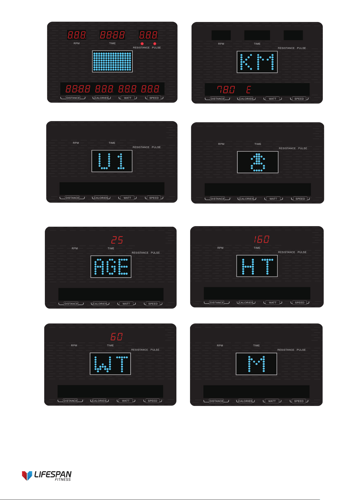
OPERATION PROCEDURE:
1. Power on
Connect power (press RESET key for 2s), buzzer sound for 1s and LED will full display 2s (Drawing 1), then
display wheel diameter and KM (or ML) in middle window and “E” (or “A”) in CALORIE window (Drawing 2). Then
go to user setting mode.
2. User profile setting
2-1 System default user group is U1 (Drawing 3), press UP or DOWN to select U1~U4, press MODE button to
confirm. Press “+” or “-” buttons to set SEX (Drawing 4), AGE (Drawing 5), HEIGHT (Drawing 6), WEIGHT
(Drawing 7) and confirm by pressing MODE. When finish setting, system enter function selection page (Drawing
8).
2-2 SEX- Female/Male; AGE- 1~99 (default value is last input value); HEIGHT- 100~200CM (default value is last
input value); WEIGHT- 20~150KG (default value is last input value).
17
Drawing 1 Drawing 2
Drawing 3 Drawing 4
Drawing 5 Drawing 6
Drawing 7 Drawing 8
3. Power off
When there is no RPM signal input for 4 minutes, LED and console go to SLEEPING mode.
Without stop power supply, user can press any key or start pedaling to wake up it.
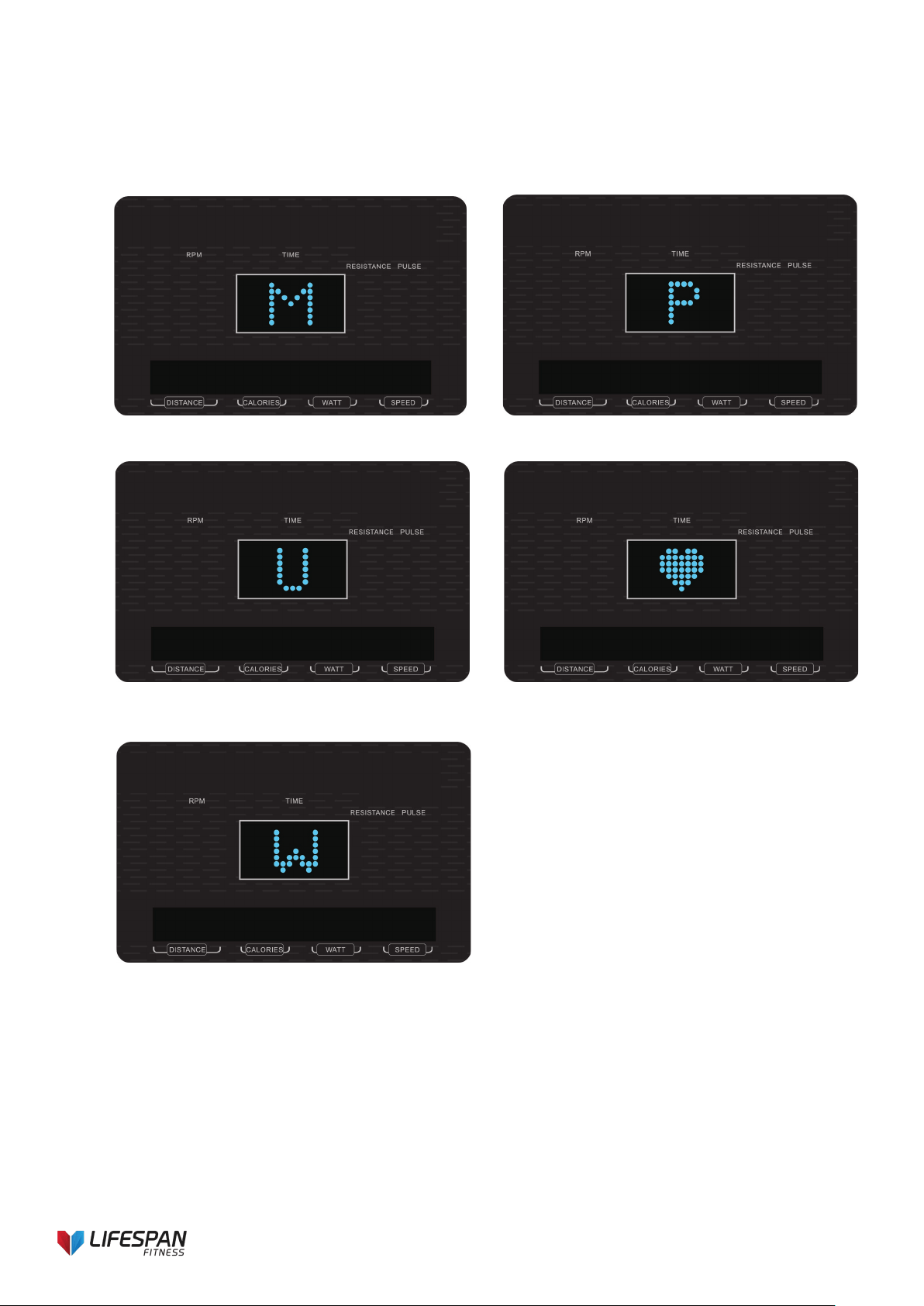
18
4. Training mode selection
After USER DATA setting, then come to main menu, user can press “P” (PROGRAM) or “+/-” to select: MANUAL
-> PROGRAM ->USER -> H.R.C. ->WATT (Drawing 9-13), LED is lighting in center window, press MODE to
confirm.
In main menu, user can also press START/STOP to enter Manual workout mode directly.
Drawing 9 Drawing 10
Drawing 11 Drawing 12
Drawing 13
4.1. Manual mode
In main menu, press “P” (PROGRAM) key or press “+”/”-” to select MANUAL, press MODE to enter MANUAL
mode.
Before exercising, user needs to adjust the following values:
TIME: is blinking (Drawing 14). User may press “+” or “-” button to set up target training time from 00:00 to
99:00. Press MODE to confirm setting.
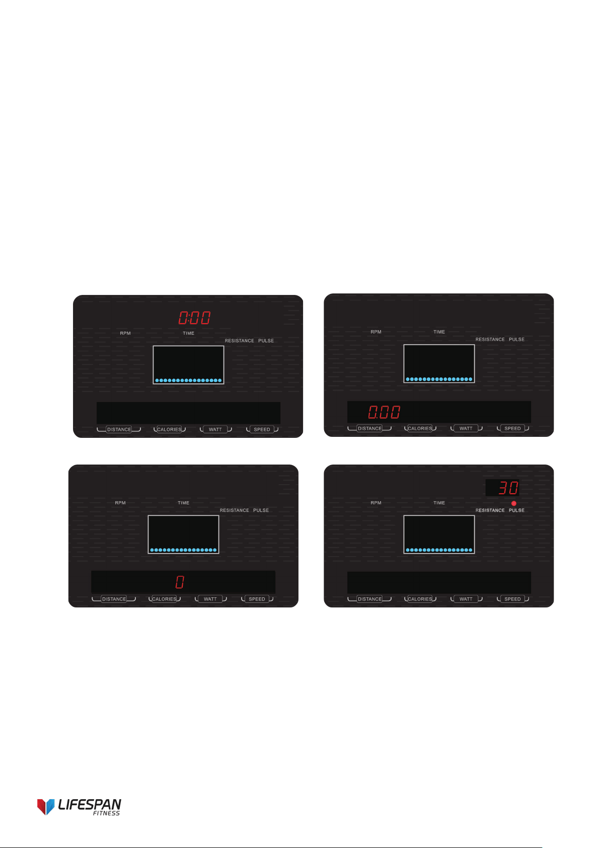
19
DISTANCE: is blinking (Drawing 15). User may press “+” or “-” button to set up target distance from 0.0~99.0.
Press MODE to confirm setting.
CALORIES: is blinking (Drawing 16). User may press “+” or “-” button to set up target calories from 0~990, the
increment/decrement is 10. Press MODE to confirm setting.
PULSE: is blinking (Drawing 17). User may press “+” or “-” button to set up target pulse from 0-30~230. Press
MODE to confirm setting. The console will detect user’s Heart Rate, please hold on hand grip sensor or ensure
chest belt is on correctly when you start exercise.
During setting, TIME/ DISTANCE/ CALORIES light will light up and the value is flashing in 1Hz to be adjusted.
Press “+” or “-” to adjust value. If you keep pressing on “+” or “-” button, the value will continue to
increase/decrease. When exercise starts, PULSE LED will light up and display pulse value; if no pulse signal
input is received, PULSE window display “P”.
Press START/STOP button to start training.
During training, user can adjust resistance level by pressing “+” or “-” button. When adjusting resistance level,
RESISTANCE window will show LEVEL value for 2s then display PULSE value.
The blue column starts blinking one by one and switch to the next one per preset time divided into 16. Once the
preset target data counting down to 0, the monitor will stop automatically.
User may also press START/STOP button to stop training. Press RESET to return to main menu.
Drawing 14 Drawing 15
Drawing 16 Drawing 17
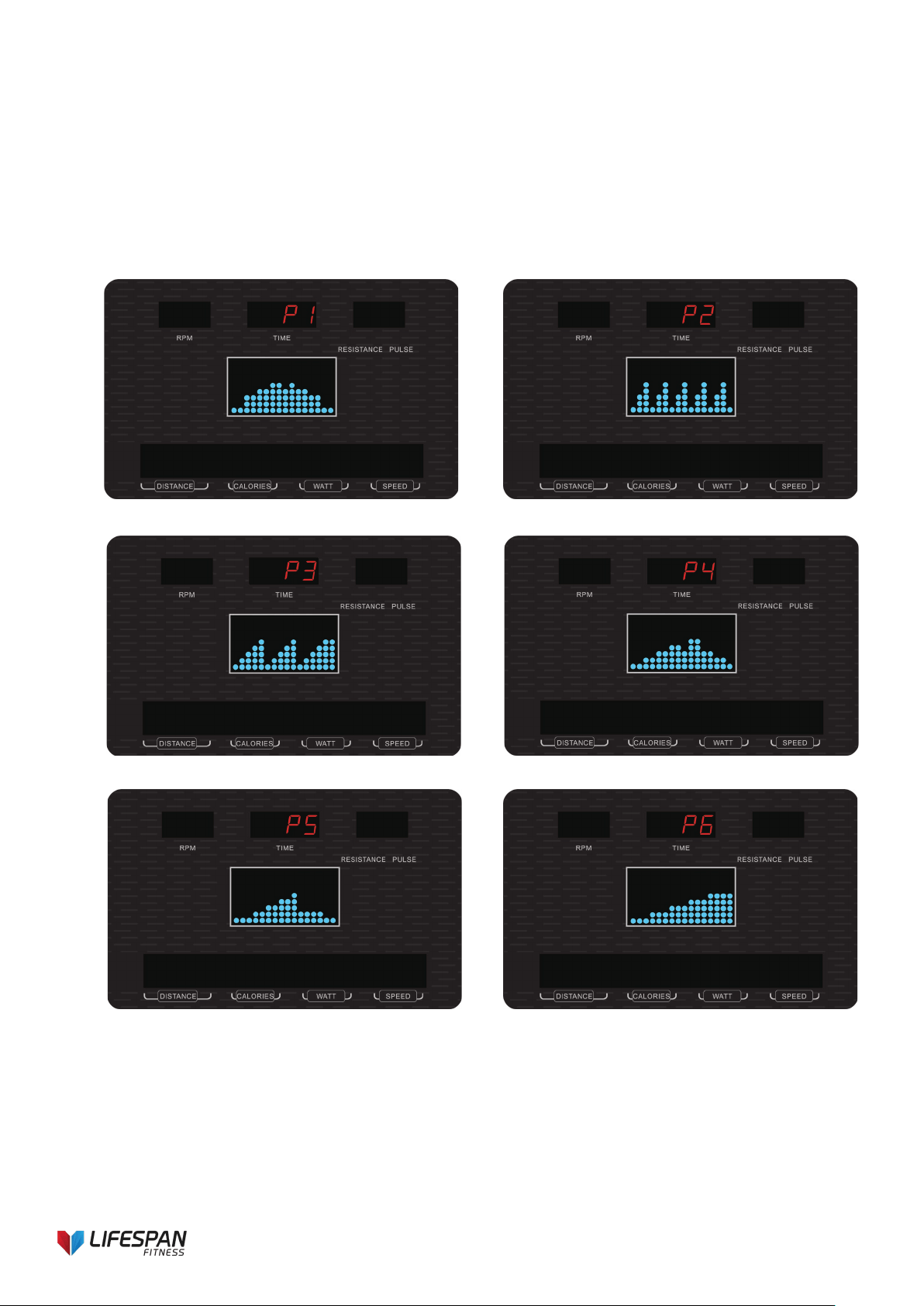
4.2. Program mode
Press RESET key to go to main menu. Press “+” or “-” key and press MODE to enter PROGRAM mode.
Entering Program mode, there are total 12 program profiles (P1~P12) (Drawing 18~29) for selection. Press “+”
or “-” key button to select one profile you prefer and press MODE to confirm.
Before exercising, user needs to adjust the following value:
TIME: is blinking (Drawing 30). User may press “+” or “-” key to set up target training time from 00:00 to 99:00
(Drawing 31).
DISTANCE: is blinking. User may press “+” or “-” button to set up target distance from 0.0~99.0. Press MODE to
20
confirm setting.
CALORIES: is blinking. User may press “+” or “-” button to set up target calories from 0~990, the
increment/decrement is 10. Press MODE to confirm setting.
PULSE: is blinking. User may press “+” or “-” button to set up target pulse from 0-30~230. Press MODE to
confirm setting.
Press START/STOP button to start training.
During training mode, user can also adjust resistance level by pressing “+” or “-” button. When adjusting
resistance level, LED big window will show LEVEL value for 2s then display PULSE value.
Once the preset target data counts down to 0, the monitor will stop automatically.
User may also press START/STOP button to stop training. Press RESET to return to main menu.
Drawing 18 Drawing 19
Drawing 20 Drawing 21
Drawing 22 Drawing 23
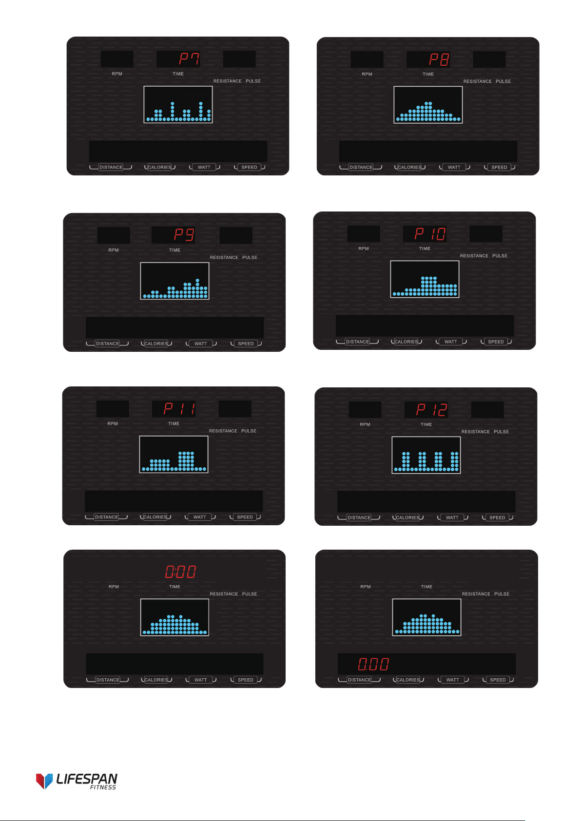
21
Drawing 24 Drawing 25
Drawing 26 Drawing 27
Drawing 28 Drawing 29
Drawing 30 Drawing 31
22
4.3. User (program) mode
Press RESET key to go to main menu. Press “+” or “-” key and press MODE to enter USER program. User may
create their own profile in this mode. The first blue dot of the profile will start blinking, then press “+” or “-” button
to adjust resistance level of each column dot (Drawing 32), then press MODE to confirm. A complete program
profile will have 16 columns to be set (default value =1). To finish or quit a setting, hold on MODE button for 2s.
Then adjust the following value:
TIME: is blinking (Drawing 33). You may press “+” or “-” button to set up target training time from 00:00 to 99:00.
Press START/STOP button to start training.
During training mode, user can also adjust resistance level by pressing “+” or “-” button.
Once the preset target data counts down to 0, the monitor will stop automatically. You may press START/STOP
button to start training again. Other preset data will keep counting down from previous data. During STOP mode,
user can press RESET button to return to main menu.
Drawing 32 Drawing 33
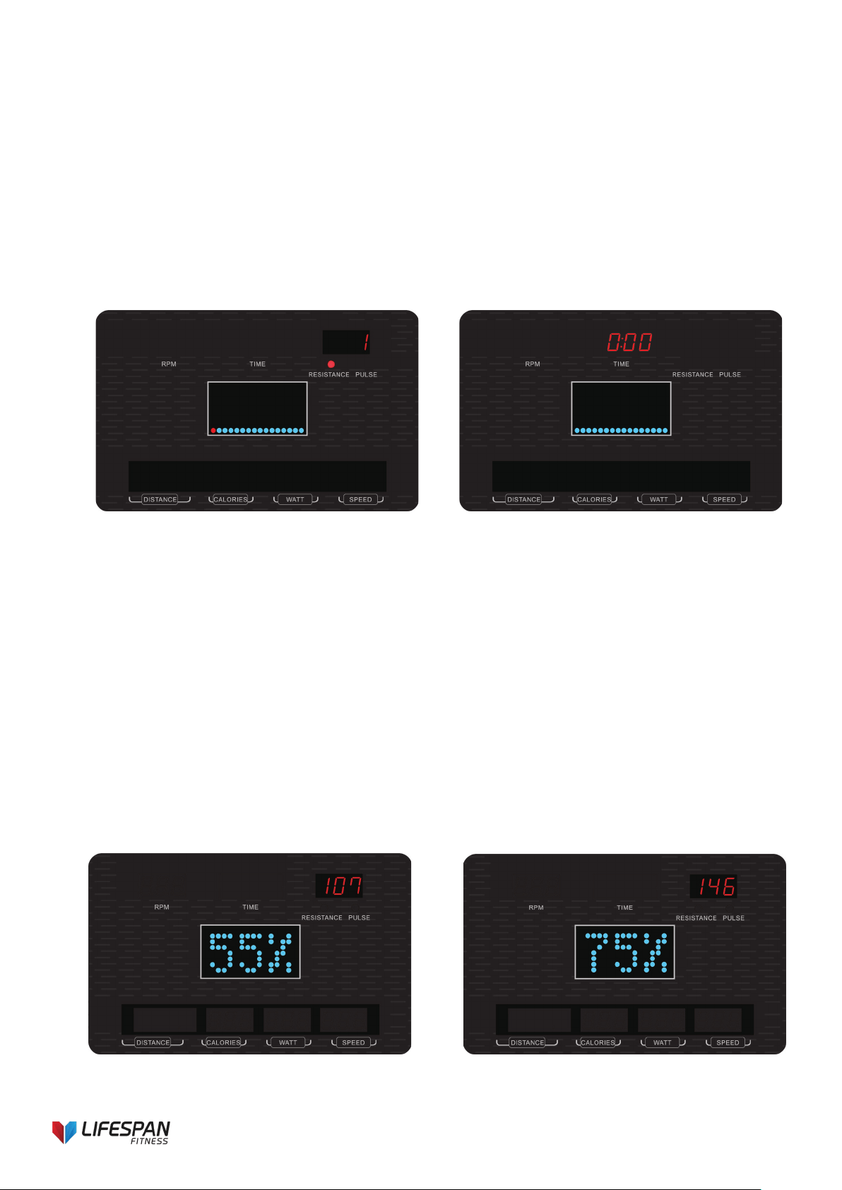
4.4. H.R.C. mode
Press RESET key to go to main menu. Press “+” or “-” button and press MODE to enter H.R.C. mode. In H.R.C.
mode, press “+” or “-” button to choose: 55%, 75%, 90% or TAG. The LED will be blinking. User may choose
different target heart rates, the preset value system self-calculated based on user input AGE will display in
PULSE window (Drawing 34~37). Press MODE to confirm. If user select H.R.C TAG, screen will display the
preset value 100, press “+” or “-” to adjust target pulse from 30~230. Press MODE button to enter.
Then adjust following value:
TIME: is blinking. You may press “+” or “-” button to set up target training time from 00:00 to 99:00. (Drawing
38).
Press START/STOP button to start training.
During training, the resistance level will adjust automatically according your current heart rate.
If no pulse signal detected, central LED will reminder by showing as Drawing 39.
Press STOP to pause workout, press RESET button to reverse to main menu.
※H.R.C 55% - Diet program; H.R.C 75% - Health program; H.R.C 90% - Sports program
Drawing 34 Drawing 35
23
Drawing 36 Drawing 37
Drawing 38 Drawing 39
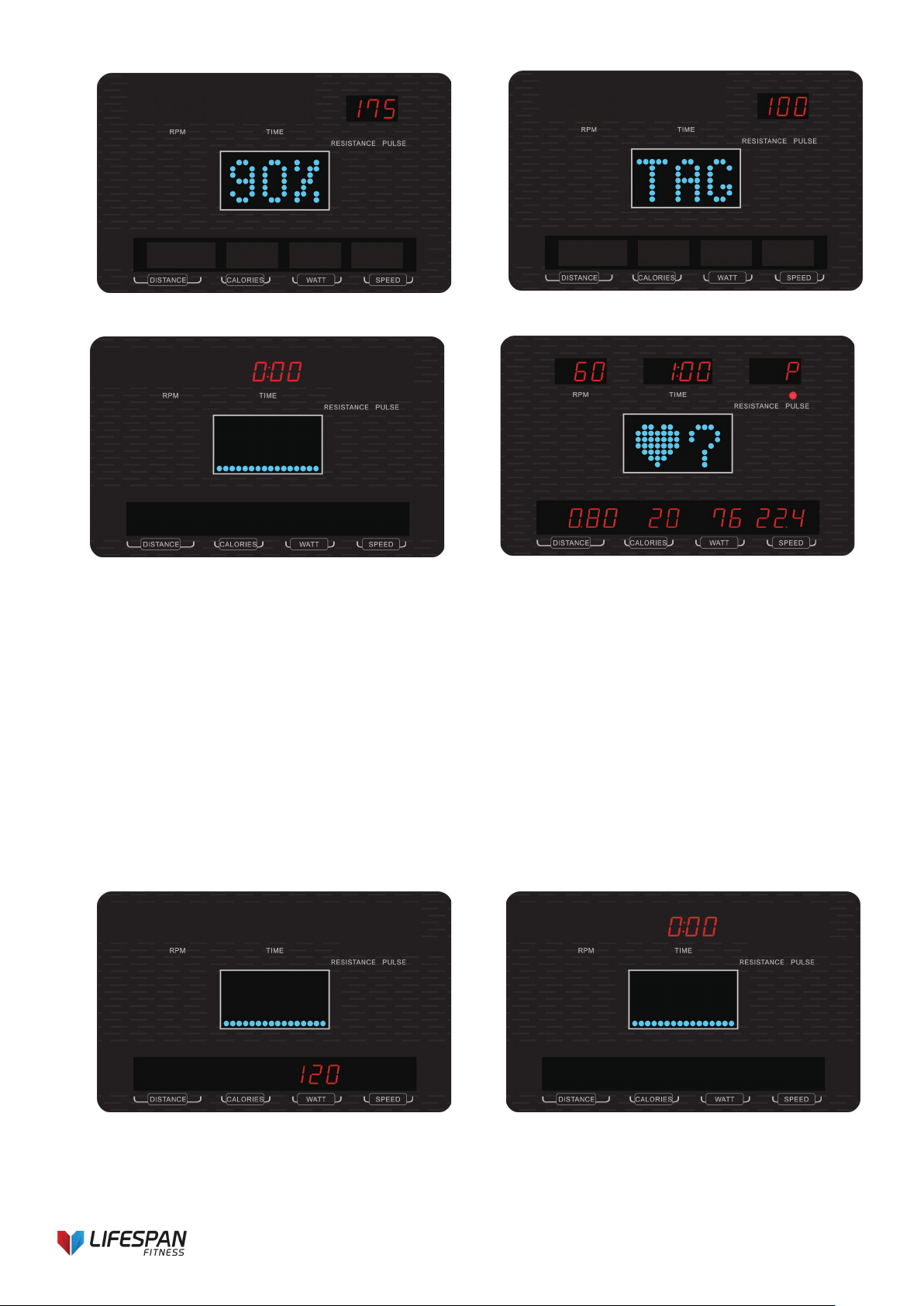
4.5. WATT control mode
When user in any mode, press START/STOP button then press RESET to go to main menu.
Press “+” or “-” button and press MODE to enter WATT constant training mode. Entering WATT mode, the preset
value 120 is blinking (Drawing 40). User may adjust WATT value by pressing “+” or “-” button from 10~350 with
5W increment and press MODE to confirm.
Then adjust following value:
TIME: is blinking. You may press “+” or “-” button to set up target training time from 00:00 to 99:00. (Drawing 41)
Press START/STOP button to start training.
System will adjust WATT level automatically according to the preset target watt data, current RPM and training
speed. If the training speed is quick, resistance level will decrease. Otherwise, it will increase. When stop
training, user can press RESET button to return to main menu.
Drawing 40 Drawing 41
24
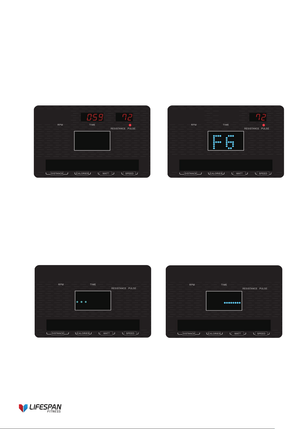
5. RECOVERY mode
If there is no pulse signal input to console, it is invalid to press RECOVERY button.
When pulse value appears on screen, press RECOVERY button to start test. Keep both hands hold on hand
grips (or wear chest belt). All function display will stop except “TIME” starts counting down from 00:60 by second
(Drawing 42) and PULSE light is ON. System resistance will reduce to level 1.
While TIME counts down to 00:00, screen will display heart rate recovery status with “FX” (X=1...6) (Drawing
43). F1 is the best, F6 is the worst.
Press RECOVERY button again to go to previous workout status.
If user press RECOVERY prior to TIME counting down to 00:00, RECOVERY mode will be disable and console
go to main menu.
Drawing 42 Drawing 43
6. BODY FAT mode
In STOP mode, press the BODY FAT button to start body fat measurement. System will start measuring. During
measuring, user needs to hold both hands on the hand grip. The screen will display as Drawing 44~46 until
console finishes measuring. After measuring, screen will display BODY FAT percentage and BMI (Body Mass
Index) and FAT advice (Drawing 47~48).
Press BODY FAT button again to go back to previous workout status.
※Error code display during measurement:
E-1--- user not hold hand grips correctly (Drawing 49)
E-4--- Body Fat% exceed setting range (5.0%~ 50%). (Drawing 50)
Drawing 44 Drawing 45
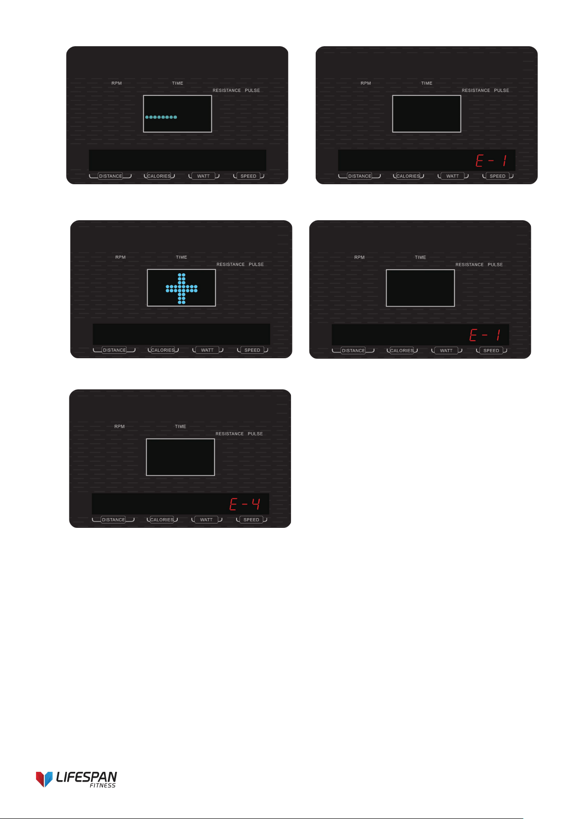
25
Drawing 46 Drawing 47
Drawing 48 Drawing 49
Drawing 50
NOTE:
1. When user press RESET button for 2 seconds for TOTAL RESET, console enter to START mode, buzzer
alarm 1s, all LED display for 2s, then go to setting mode. Load level is 1.
2. This system is built with ALARM reminder:
1 short beep - valid button
2 short beeps - invalid button or pulse exceed Target value
3 short beeps per second - WATT is over Spec
4 short beeps- function value counts down to 0
6 short beeps- H.R.C. & WATT control force system to stop
Other function (optional):
1. USB charger- The console can provide USB port for mobile or tablet charging.
2. MP3 player- The console is built with speaker, user can connect it to mobile device for MP3
3. function.
4. Fan- The console is provided with fan, user can open or close the fan.
26
7. EXERCISE GUIDE
PLEASE NOTE: Before beginning any exercise program, consult your physician. This is important
especially if you are over the age of 45 or individuals with pre-existing health problems.
The pulse sensors are not medical devices. Various factors, including the user’s movement, may affect
the accuracy of heart rate readings. The pulse sensors are intended only as an exercise aid in
determining heart rate trends in general.
Exercising is a great way to control your weight, improving your fitness and reduce the effect of aging and stress.
The key to success is to make exercise a regular and enjoyable part of your everyday life.
The condition of your heart and lungs and how efficient they are in delivering oxygen via your blood to your
muscles is an important factor to your fitness. Your muscles use this oxygen to provide enough energy for daily
activity. This is called aerobic activity. When you are fit, your heart will not have to work as hard. It will pump a lot
fewer times per minute, reducing the wear and tear of your heart.
So the fitter you are, the healthier and greater you will feel.
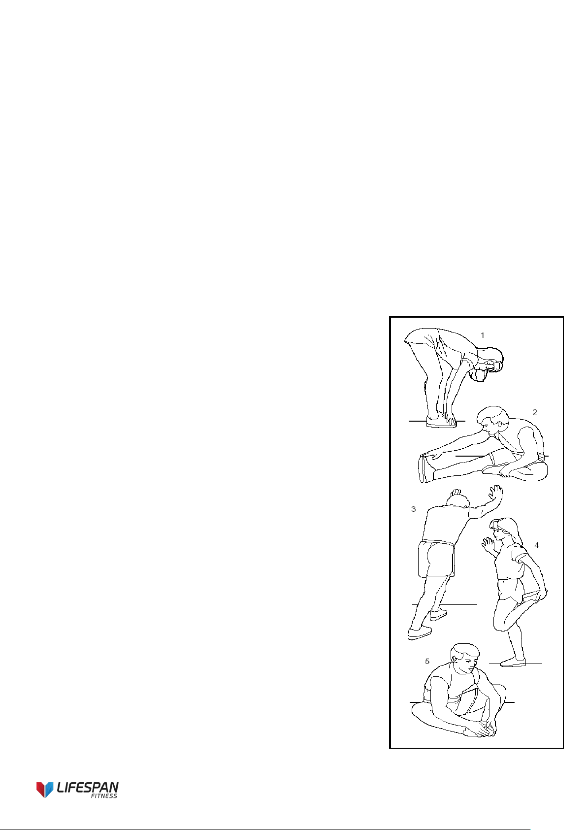
Warm-up / stretching exercises
A successful exercise session begins with warming up exercises and ends
with
exercises for cooling down and relaxing. These warming up exercises
prepare your body for the subsequent demands made upon it. The cooling
down / relaxation period after the exercise session ensures that you do not
experience any muscular problems. In the following you will find stretching
exercise instructions for warming up and cooling down.
Please pay attention to the following points:
1. TOUCH TOES
Bend your trunk slowly forwards and try to touch your feet with your hands.
Reach down
as far as possible to your toes. Maintain this position for 10-15 seconds if
possible.
2
.EXERCISES FOR THE KNEES
Sit on the floor and stretch out your right leg. Bend your left leg and place
your foot on
your right upper thigh. Now try to reach your right foot with your right arm.
Maintain
3. EXERCISES FOR THE CALVES/ACHILLES TENDON
Place both hands on the wall and support your full body weight. Then
move your left leg backwards and alternate it with your right leg. This
stretches the back of the leg. Maintain this position for 30-40 seconds if
possible.
4. EXERCISES FOR THE UPPER THIGH
Support yourself by placing your hand on the wall, then reach down behind
you and lift your right or left foot as close to your buttocks as possible. Feel
a comfortable tension in your front upper thigh. Maintain this position for 30
seconds if possible and repeat this exercise 2 times for each leg.
27
5. INSIDE UPPER THIGH
Sit on the floor and place your feet in such a way that your knees are facing outwards. Pull your feet as close as
possible to your groin. Now press your knees carefully downwards. Maintain this position for 30-40 seconds if
possible.
Training Zone Exercise
After warming up, increase the intensity to your desired exercise program. Be sure to maintain your intensity for
maximum performance. Breathe regularly and deeply as you exercise.
Cool Down
Finish each workout with a light jog or walk for at least 1 minute. Then complete 5 to 10 minutes of stretching to
cool down. This will increase the flexibility of your muscles and will help prevent problems post-exercise.
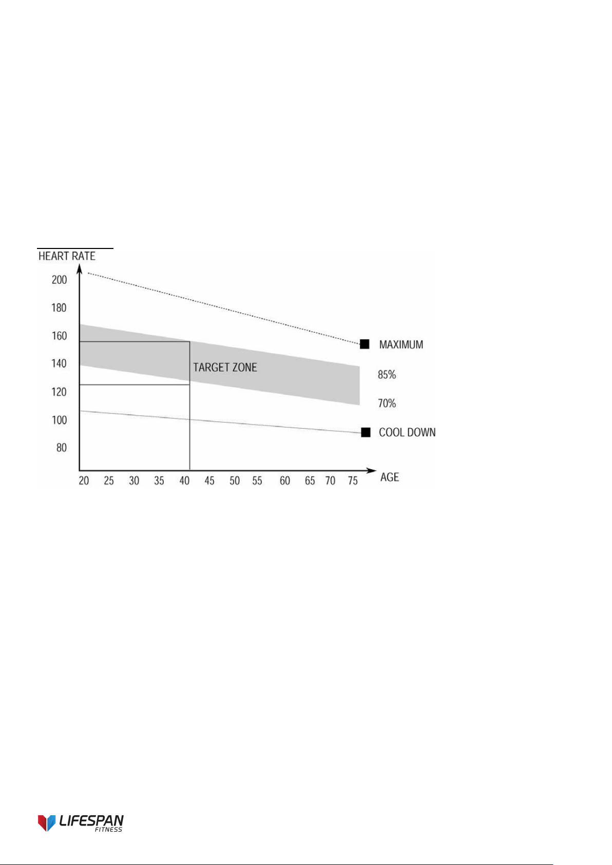
Workout Guidelines
TARGET ZONE
This is how your pulse should behave during general fitness exercise. Remember to warm up and cool
down for a few minutes.
The most important factor here is the amount of effort you put in. The harder and longer you work, the more
calories you will burn.

28
8. WARRANTY
AUSTRALIAN CONSUMER LAW
Many of our products come with a guarantee or warranty from the manufacturer. In addition, they come with
guarantees that cannot be excluded under the Australian Consumer Law. You are entitled to a replacement or
refund for a major failure and compensation for any other reasonably foreseeable loss or damage.
You are entitled to have the goods repaired or replaced if the goods fail to be of acceptable quality and the
failure does not amount to a major failure. Full details of your consumer rights may be found at
www.consumerlaw.gov.au
Please visit our website to view our full warranty terms and conditions:
http://www.lifespanfitness.com.au/warranty-repairs
Warranty and Support:
Please email us at support@lifespanfitness.com.au
for all warranty or support issues.
For all warranty or support related enquiries an email must be sent before contacting us via any other means.

29
Hand Pulse Technology
This product comes equipped with hand pulse sensors which are used to pick up tiny EKG/ECG signals
that run through the body when your heart beats. These electrical EKG/ECG signals are very small and
they must be amplified 1000 times to make the signal useful for the computer to display your pulse.
To ensure proper operation:
- The user must maintain good, consistent contact on all four sensors
- The users skin cannot be too dry or too wet
Other factors that could affect the reading:
- Change of grip on the sensors (during slow pace walking and up to running speeds)
- Tightening of hand muscles will produce small electrical signals
- Static electricity charges from the air or from walking on the treadmill
EKG/ECG sensors may filter through actual EKG/ECG signals and “Noise” factors that may affect the
reading. This will cause the pulse reading to be delayed and will take longer to update the display as the
heart rate changes. Too much noise will create an incorrect reading. Medical conditions or having no
electrical signal in the hands are other factors that may also affect pulse readings.
These are limitations of hand pulse technology and even the most expensive systems (which can cost
upwards of $3,000) used in hospitals have the same problems. The difference is that a patient in a hospital
is not running on a treadmill. Hand pulse technology works well on stationary exercise machines like bikes
and even elliptical cross trainers but are not perfect on a treadmill. We offer treadmills with a wireless heart
rate receiver which may be a more accurate option.
To test if your hand pulse sensors are working up to specification, hold them while standing on the side
step rails, not walking, and see if the reading is more in line with what you would expect. This will eliminate
the movement and static electricity factors. If your hands are dry, then wet them slightly (saliva works as a
great conductor if this doesn’t bother you).
For more information, please contact our Lifespan Technical Support Department
www.lifespanfitness.com.au
support@lifespanfitness.com.au