Loading ...
Loading ...
Loading ...
5
800.558.1711 Installation & Operation Instructions
OUTLET DUCT
COLLAR WITH
BACK DRAFT
DAMPER
RETURN AIR
INLET DUCT
COLLAR
FRESH AIR
INLET DUCT
COLLAR
RETURN AIR
INLET DUCT
COLLAR
FRESH AIR
INLET DUCT
COLLAR
Front View
Horizontal Flow Through
(End Discharge)
AIR FLOW
Air
Flow
Rear View
Vertical Flow Through
(Top Discharge)
6" Fresh Air Inlet (Optional)
10" Return Air Inlet
10" Supply Air Outlet
A
B
C
A
B
C
A
B
C
Top View
C
6" Fresh Air Inlet (Optional)
10" Return Air Inlet
10" Supply Air Outlet
A
B
C
A
B
C
Air
Flow
Rear ViewFront View
A
B
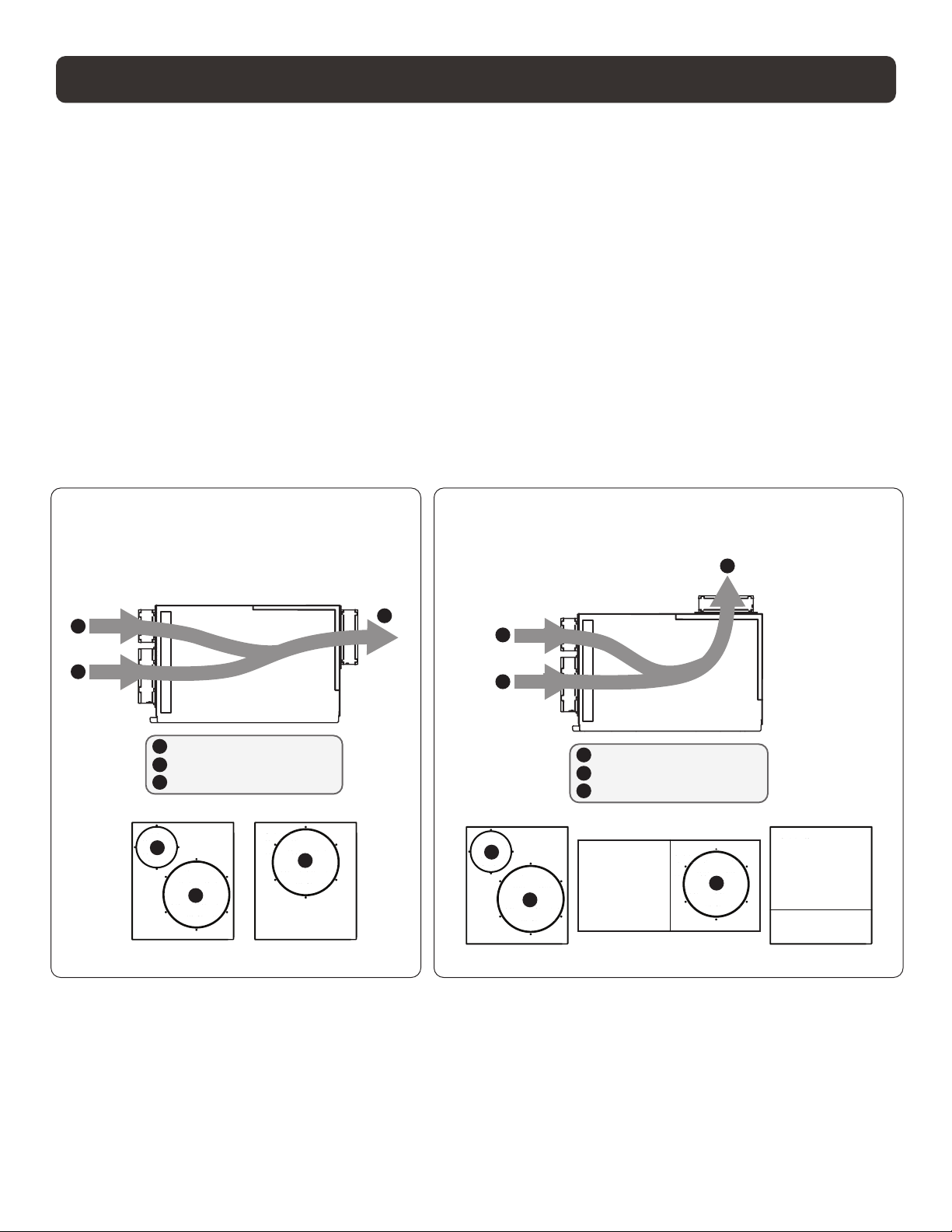
ATTACHING DUCT COLLARS
OUTLET DUCT
COLLAR WITH
BACK DRAFT
DAMPER
RETURN AIR
INLET DUCT
COLLAR
FRESH AIR
INLET DUCT
COLLAR
RETURN AIR
INLET DUCT
COLLAR
FRESH AIR
INLET DUCT
COLLAR
Front View
Horizontal Flow Through
(End Discharge)
AIR FLOW
Air
Flow
Rear View
Vertical Flow Through
(Top Discharge)
6" Fresh Air Inlet (Optional)
10" Return Air Inlet
10" Supply Air Outlet
A
B
C
A
B
C
A
B
C
Top View
C
6" Fresh Air Inlet (Optional)
10" Return Air Inlet
10" Supply Air Outlet
A
B
C
A
B
C
Air
Flow
Rear ViewFront View
A
B
Fresh Air Ventilation Duct
Fresh air ventilation is optional. A 6" diameter duct is attached to the unit. The 6" duct should be capped if
fresh air is not desired. If setting up the unit to provide fresh air ventilation, see page 10.
Return Air Inlet
A 10" diameter duct collar is attached to the unit.
Supply Air Outlet
The back panel of the dehumidier can be rotated to allow for horizontal ow through or vertical ow through
of the supply air.
• Horizontal Flow Through
The unit ships congured for a horizontal ow through. A 10" diameter duct collar is attached to the unit.
• Vertical Flow Through
Remove the exhaust panel using a T25 torx bit. Rotate the panel so the exhaust collar is located on the top
of the unit. Align screw holes and snap the panel onto the base. Secure the exhaust panel to the base by
replacing the six screws.
Loading ...
Loading ...
Loading ...