Loading ...
Loading ...
Loading ...
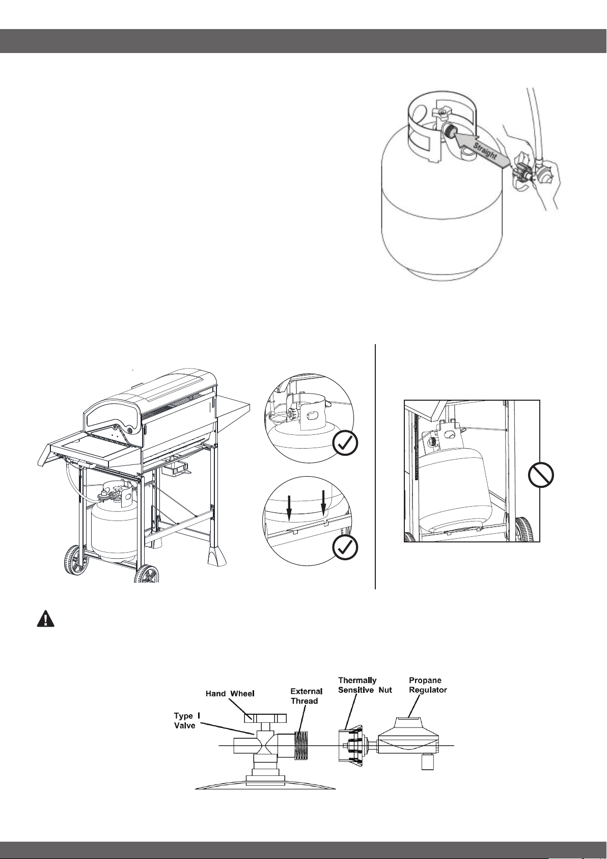
Gas tank must be placed onto the slot on right side beam vertically and be sure the cylinder hook
is placed correctly on the left side collar of the tank (see Fig.3a). DO NOT operate the grill if the
gas tank is tilted or the hook is placed incorrectly (see Fig. 3b)
CONNECTING REGULATOR TO THE LP TANK
22
2. Check the tank valve to ensure it has proper external mating
threads to t the hose and regulator assembly provided (Type
1 connection per ANSI Z21.58b-2002).
3. Make sure all burner knobs are in the OFF position.
4. Remove the protective cap from the LP tank valve and
coupling nut. And inspect the valve connection port of the
regulator assembly. Look for damage or debris. Remove any
debris. Inspect hose for damage. Never use damaged or
plugged equipment.
5. Hold regulator by one hand in a straight line with LP tank
valve and insert nipple into LP tank valve. Be sure the nipple is
centered in the valve outlet. (see Fig. 2) Hand-tighten coupling
nut clockwise until it comes to a full stop. DO NOT use tools!
6. Open the tank valve fully (counterclockwise).
7. Perform leak test before attempting to light your grill. See
“CHECKING FOR LEAKS “ on page 20.
Fig. 2
Fig. 3a Fig. 3b
WARNING: The Type I connective coupling (see Fig. 4) supplied with your grill must not be
replaced with a different type of grill/tank connection system. Removal will result in loss of warranty, gas
leakage, re and severe bodily harm.
Fig. 4
Loading ...
Loading ...
Loading ...