DO NOT RETURN YOUR GRILL TO THE STORE
Before visiting your local retailer, call our customer
service department at 1-866-994-6390 from 9:00 am
to 5:00 pm Eastern Time, Monday through Friday.
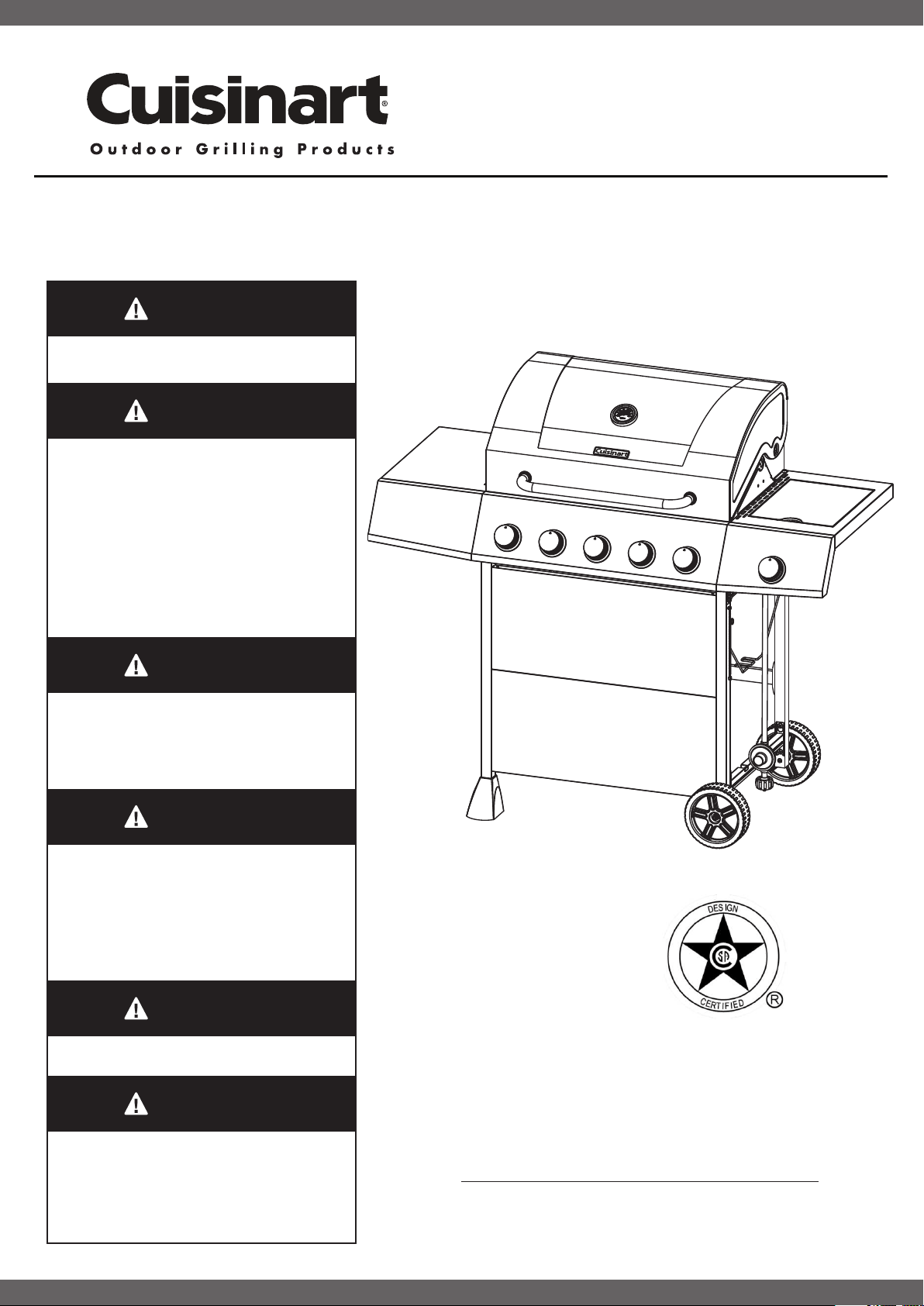
Model NO: CGG-8500
5 Burner Gas Grill
Customer Service Hotline
1-866-994-6390
For Outdoor Use Only (outside any enclosure).
1. Improper installation, adjustment, alteration, service
or maintenance can cause injury or property damage.
2. Read this instruction manual thoroughly before
installing or servicing this equipment.
3. Failure to follow these instructions could result in
re or explosion, which could cause property damage,
personal injury or death.
4. This instruction manual contains important
information necessary for proper assembly and safe
use this appliance.
5. Always keep this manual for convenient future
reference.
1. DO NOT store or use gasoline or other ammable
vapors and liquids in the vicinity of this or any other
appliance.
2. An LP tank not connected for use should not be
stored in the vicinity of this or any other appliance.
If you smell gas:
1. Shut off gas to the appliance.
2. Extinguish any open ames.
3. Open the lid.
4. If the odor continues, keep away from the appliance
and immediately call your gas supplier or re
department.
Never operate this appliance unattended.
Check for leaks every time prior to you light the grill,
even if purchased fully assembled. Gas leaks may
cause a re or explosion.
Please read the instructions on Page 23.
OWNER’S MANUAL
ASSEMBLY AND
OPERATING INSTRUCTIONS
WARNING
WARNING
WARNING
DANGER
DANGER
DANGER
IMPORTANT: ALL INSTRUCTIONS AND SAFEGUARDS ON THIS SECTION MUST BE FOLLOWED TO
PREVENT DAMAGE AND/OR INJURY.
IMPORTANT SAFETY INFORMATION
For outdoor use only. Do not use near or inside a building, garage or any other enclosed area.
Do NOT operate, light or use this appliance within 8 feet of walls, structures or buildings.
This grill is NOT for commercial use.
This grill is for use with liquid propane (LP) gas only. The conversion to or attempted use of natural gas in this LP
gas grill is dangerous and will void your warranty.
The installation of this appliance must conform with local codes or, in the absence of local codes, with either the
National Fuel Gas Code, ANSI Z223.1/NFPA 54, or Natural Gas and Propane Installation Code, CSA/
CG A- B149.1.
This outdoor cooking gas appliance must not be placed under overhead combustible construction.
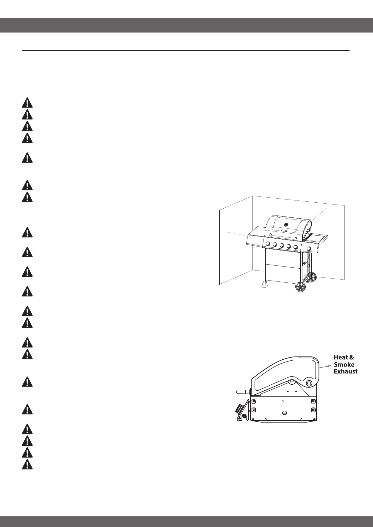
A minimum clearance of 36 inches from combustible
constructions to the sides of the grill and 36 inches from the
back of the grill to Combustible constructions must be
maintained.
Keep your grill in an area clear and free from combustible
materials, gasoline and other ammable vapors and liquids.
This outdoor grill is not intended for installation in or on
recreation vehicles and/or Boats.
DO NOT leave a lit grill unattended.
Keep children and pets away from the grill at all times.
Do not use the grill unless it is COMPLETELY assembled and all parts
are securely fastened and tightened.
DO NOT place this grill on any type of tabletop surface. The grill should be placed on a at and level surface.
The grill must be isolated from the gas supply piping system by closing its individual manual shutoff valve during
any pressure testing of the gas supply system at test pressures equal to or less than 1/2 psi (3.5 KPa).
Never use the grill in windy areas. The grill will operate best if it is not facing directly into the wind.
Heat and smoke exhaust out of the back of the grill hood opening.
Never have the grill back facing your home or anything that could be
damaged by heat or smoke.
DO NOT touch metal parts of grill until it has completely cooled
about 45 minutes) to avoid burns, unless you are wearing protective
gear (pot holders, gloves, BBQ mittens, etc…).
ALWAYS open grill lid slowly and carefully as heat and steam
trapped within the grill can burn
DO NOT obstruct the ow of combustion and ventilation air to this appliance.
Keep all electrical cords away from a hot grill.
DO NOT use grill for indoor cooking or heating. TOXIC fumes can accumulate and cause asphyxiation.
After a period of storage and/or nonuse, check for leaks, burner obstructions and inspect for any abrasion,
wear, cuts to the hose.
Warnings and Usage
SAFETY INFORMATION
2
36"(914mm)
36"(914mm)
SAFETY INFORMATION
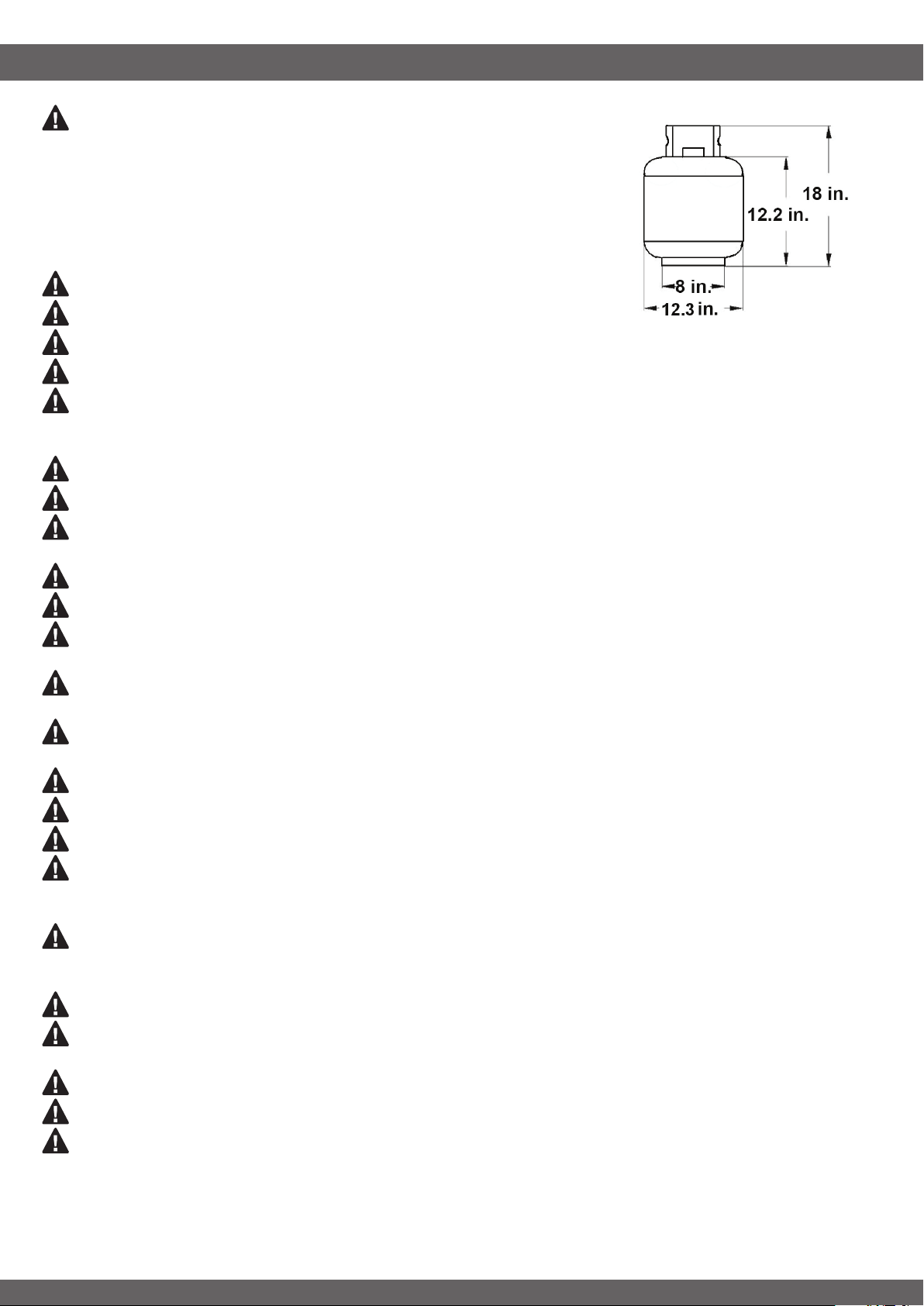
The LP gas cylinder used with this appliance must be:
(a) Constructed and marked in accordance with the Specications for LP-Gas
Cylinders of the U.S. Department of Transportation (D.O.T.) or the National
Standard of Canada, CAN/CSA-B339, Cylinders, Spheres and Tubes for
Transportation of Dangerous Goods; and Commission, as applicable; and
(b) Provided with a listed overlling prevention device.
(c) Provided with a cylinder connection device compatible with the connector
for outdoor cooking appliances.
The LP cylinder used must include a collar to protect the cylinder valve.
DO NOT store a spare LP-gas cylinder under or near this appliance.
An LP cylinder not connected for use shall not be stored in the vicinity of this or any other appliance.
Never ll the cylinder beyond 80 percent full.
Inspect the hoses before each use for excessive abrasion or wear, or cuts that may affect safe operation of the
grill. If there is evidence of excessive abrasion or wear, or the hose is cut, it must be replaced prior to the gril
being put into operation. The replacement hose assembly must be those specied by the manufacturer.
Never use charcoal, lighter uid, lava rocks, gasoline, kerosene, or alcohol with this product
Move gas hoses as far away as possible from hot surfaces and dripping hot grease.
Failure to open lid while igniting the grill’s burners, or not waiting 5 minutes to allow the gas to clear if the grill
does not light, may result in an explosive ame-up.
If grill is not in use, the gas must be turned off at the supply tank.
Never operate grill without ame tamers installed.
DO NOT wrap the cooking grates in foil or completely cover the top surface of the grates in foil as this can lead
to excessive heat and the potential for a possible re. Doing so will void your warranty.
Never use the grill without the drip tray installed and hung under the burner box. Without the drip tray, hot
grease and debris could leak downward and produce a re hazard.
Never operate this grill without the hose ring secured to the leg. This can keep the regulator hose away from hot
surfaces and dripping hot grease. Failure to do this may cause a re or explosion.
Always use a meat thermometer to ensure food is cooked to a safe temperature.
Please use protective gloves when assembling this product.
DO NOT force parts together as this can result in personal injury or damage to the product.
This grill should be thoroughly cleaned and inspected on a regular basis. Clean and inspect the hose before
each use of the appliance. If there is evidence of abrasion, wear, cuts, or leaks, the hose must be replaced prior
to the appliance being put into operation
This grill should be thoroughly cleaned and inspected on a regular basis. Clean and inspect the hose before
each use of the appliance. If there is evidence of abrasion, wear, cuts, or leaks, the hose must be replaced prior
to the appliance being put into operation
Keep the ventilation openings of the tank enclosure free and clear from debris.
Your grill has been checked at all factory connections for leaks. Recheck all connections, as movement in
shipping can loosen connections.
Check for leaks even if your unit was assembled for you by someone else.
DO NOT operate if gas leak is present. Gas leaks may cause a re or explosion.
Deaths, serious injury or damage to property may occur if the above is not followed exactly.
3
SAFETY INFORMATION
TABLE OF CONTENTS
4
Cover …………….…………......………………………….………...….………….………….….…………………..……..1
Table of Contents……...........…….……………………..….………...….………….………………..……….…….…..4
Safety Information……….….............……………………...………...….………….….………….……………..……..1-4
Exploded View…….................………….…………………….…………………….......................……….………....5
Parts List….………........................……..…..….……...…..............……………....………………...........................6
Assembly Preparation and Instructions…......................…………………...……………………….….….….....…..8
Operating the Grill…..............................................................................….....……..…………………….…........21
Cooking.......…………….…………………..........………………….…......…...….….……………………...…...25
Care and Maintenance...............….........................……….………………......…………….……...….….…...…..28
Trouble Shooting.....……................…….……………………………………..........….…………………..…....…...30
Warranty and Replacement Parts…..........……….....……….…………………….....…………..………….……...31
CALIFORNIA PROPOSITION 65 WARNING
• WARNING: This product can expose you to chemicals, including carbon monoxide, which are
known to the State of California to cause cancer. For more information go to:
www.P65Warnings.ca.gov
WARNING: We urge you to read this manual carefully and follow the recommendations
enclosed. This will ensure you receive the most enjoyable and trouble-free operation of your new gas
grill. We also advise you retain this manual for future reference.
WARNING: Your grill has been designed to operate using only the gas specied by the
manufacturer on the rating plate. DO NOT attempt to operate your grill on other gases.
Failure to follow this warning could lead to a re hazard and bodily harm and will void your warranty.
WARNING: Make certain your LP (propane) tank is lled by a reputable propane dealer. An
incorrectly lled or an overlled LP tank can be dangerous. The overlled condition combined with
the warming of the LP tank (a hot summer day, tank left in the sun, etc.) can cause LP gas to be
released by the pressure relief valve on the tank since the temperature increase causes the propane
to expand. LP gas released from the tank is ammable and can be explosive. Refer to your Owner’s
Manual for more information concerning lling your LP tank.
-----------------------------------------------------------------------------------
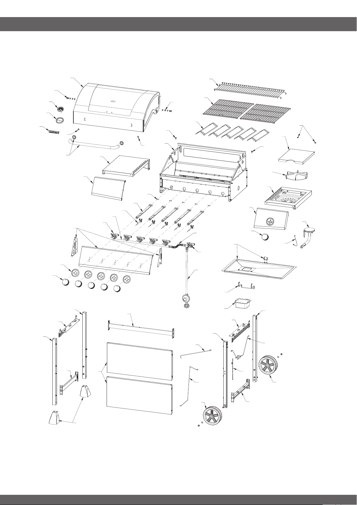
EXPLODED VIEW
5
1
2
8
2
3
5
6
6
7
9
10
11
11
12
13
15
16
19
20
21
23
24
25
33
35
36
37
38
47
39
40
41
45
43
44
48
49
50
51
34
18
27
28
29
30
25
32
31
22
17
42
26
14
51
46
4
PARTPART DESCRIPTIONDESCRIPTION
QTY
QTY
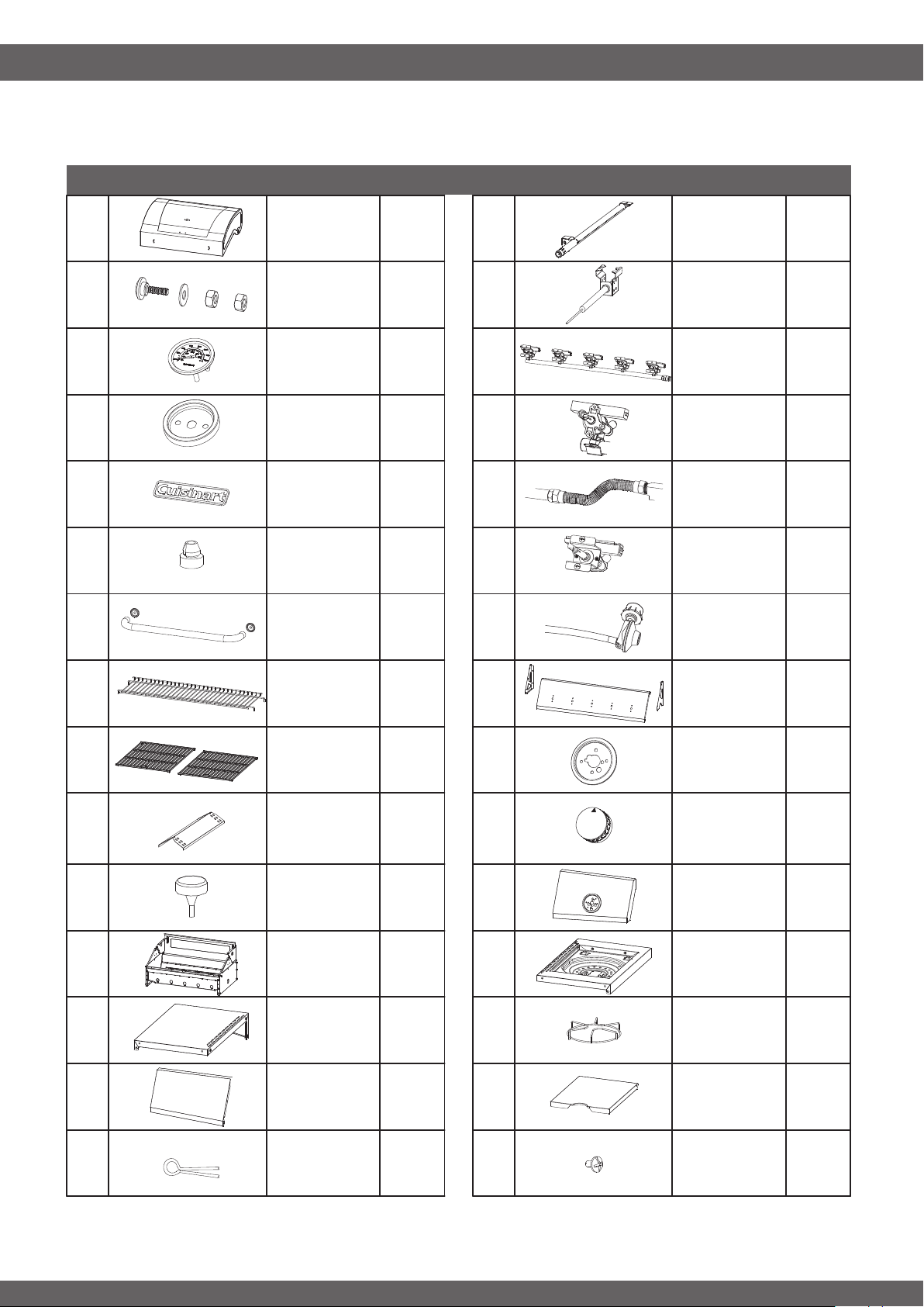
COMPONENTS
6
(x2)
(x1)
(x1)
(x1)
(x1)
(x1)
(x1)
(x2)
(x2)
(x2)
(x5)
(x1)
(x1)
(x1)
(x5)
11
10
9
12
13
14
15
(x1)
(x1)
(x1)
(x1)
27
26
25
28
29
21
22
23
24
(x1)
(x5)
(x5)
(x1)
(x1)
(x1)
(x5)
(x6)
(x5)
(x1)
1
2
3
4
5
16
17
18
19
20
6
7
8
(x2)
30
-----------------------------------------------------------------------------------
Lid Assembly
Main Burner
Locking Clip
Side Burner
Lid Hardware
Lid Hardware
Main Burner
Assembly
Lid Stopper
Side Burner
Valve
Assembly
Lid Handle
Assembly
Regulator
Warming
Rack
Control Panel
Cooking Grate
Knobs Bezel
Heat Tent
Knob
Fire Box’s
Stopper
Side Burner
Control
Fire Box
Assembly
Side Burner
Shelf Right
Left Side
Table
Side Burner
Cooking Grid
Left Side Table
Panel
Side Burner
LId
Temperature
Gauge
Main Burner
Electrode
Temperature
Gauge Bezel
Manifold
Assembly
Logo Badge
Valve
Assembly
Side Burner
Flex Gas Line
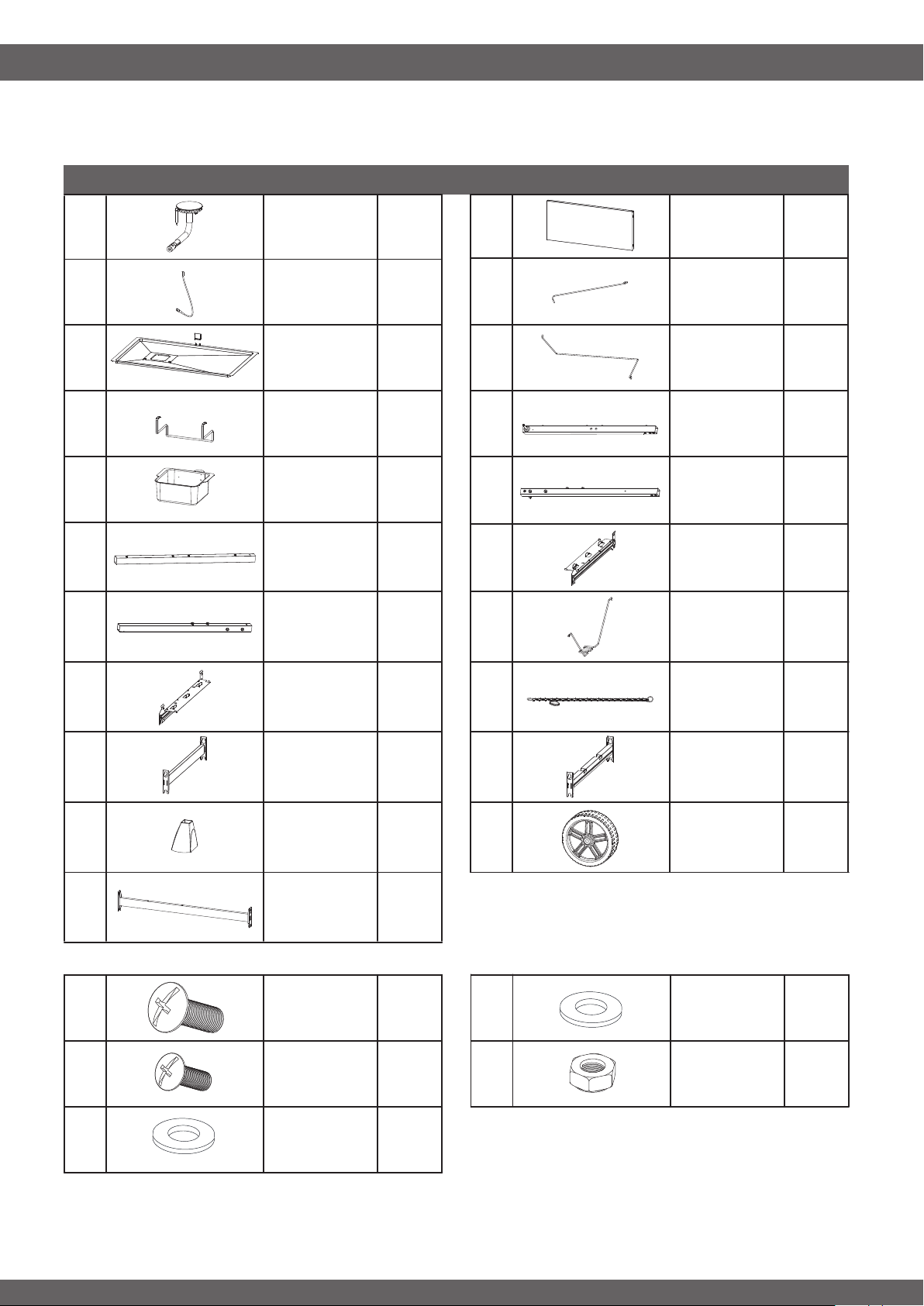
PARTPART DESCRIPTIONDESCRIPTION
QTY
QTY
COMPONENTS
7
(x1)
(x1)
(x1)
(x1)
(x2)
(x6)
(x16)
(x1)
(x1)
(x2)
(x1)
(x1)
33
32
34
35
43
42
(x1)
36
(x1)37
(x1)38
(x1)39
(x2)40
(x1)41
44
45
46
(x1)
47
(x1)48
(x1)49
(x1)50
(x2)51
A
B
C
(x2)
(x2)
D
E
(x1)
31
HARDWARE
-----------------------------------------------------------------------------------
Left Front Leg
Right Legs
Top Support
Bar
Side Burner Front Panel
Left Rear Leg
Gas Tank
Holder
Left Legs Top
Support Bar
Match Light
Holder
Left Legs
Bottom
Support Bar
Right Legs
Bottom
Support Bar
Plastic Feet
Wheel
Rear Cart
Support Bar
Truss head screw
(Black)
1/4-20X1/2”
Truss head screw
(Black)
5/32-32 x 3/8”
Flat Washer
5/32”
Wheel Washer
5/16”
Wheel Nut
5/16”
Side Burner
Igniter Wire
Wire 1
Drip Tray
Wire 2
Drip Cup
Holder
Right Front
Leg
Drip Cup
Right Rear
Leg
Assembly Tip: To avoid scratching grill and to protect oor/patio surfaces, reuse cardboard packaging and lay
parts on top of while assembling.
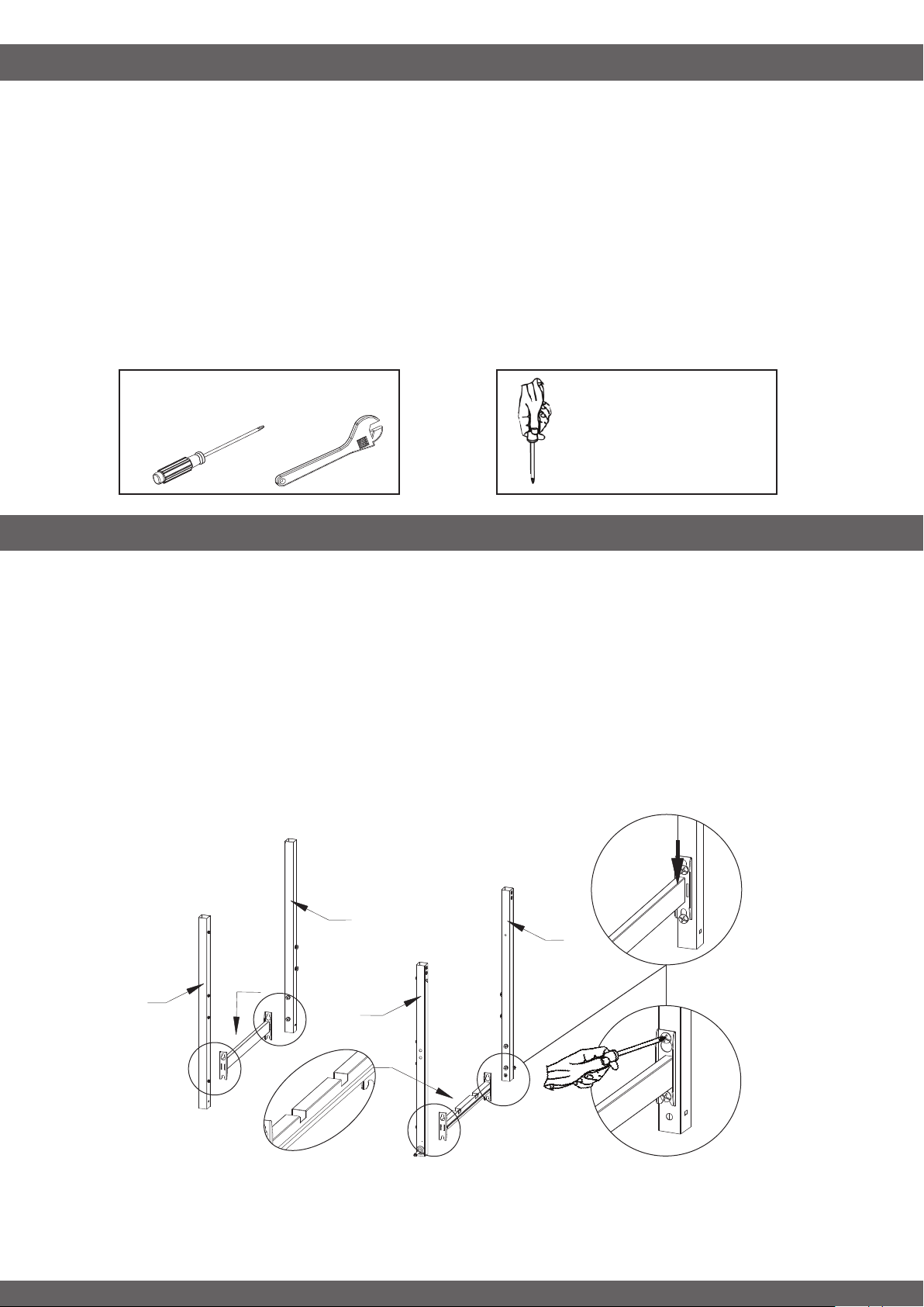
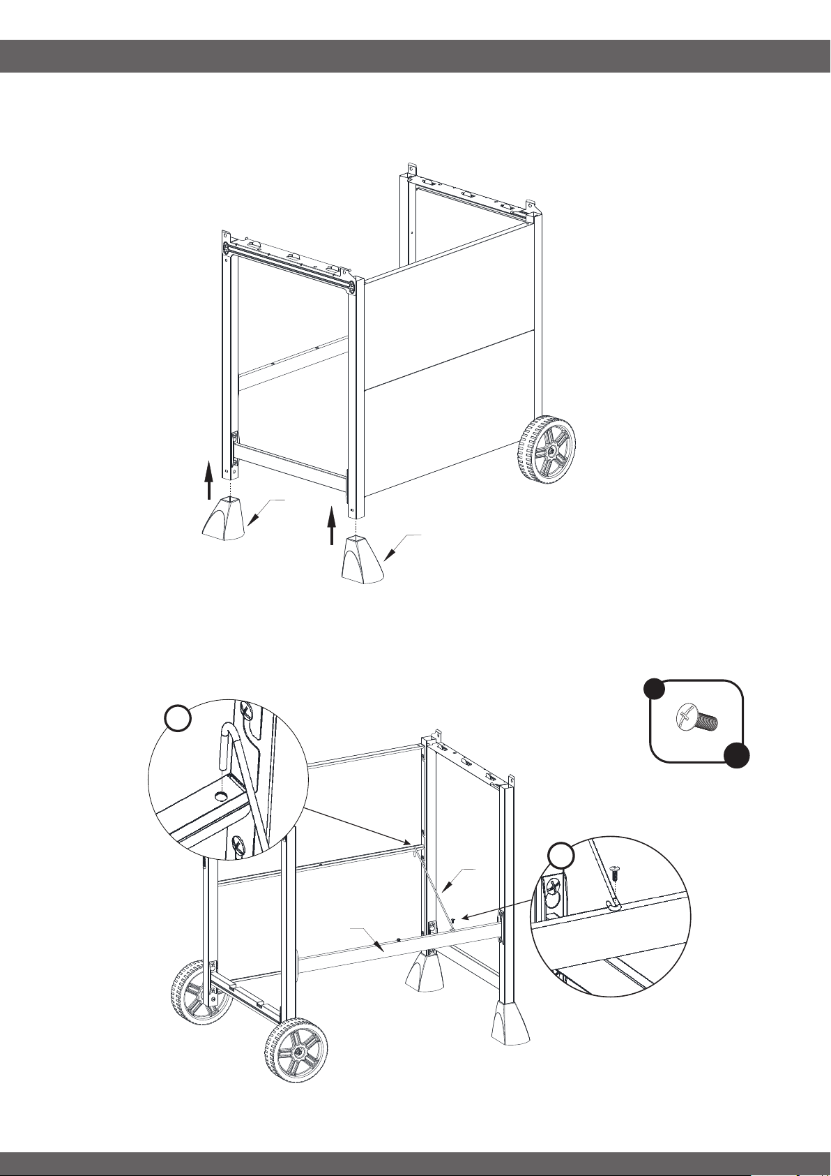
STEP 1
-----------------------------------------------------------------------------------
• Loosen the pre-assembled Leg Screws and leave the screw heads protruding approximately 5mm.
• Hang Left Leg Bottom Support Bar (39) to Left Front Leg (36) and Left Back Leg (37), then fasten
screws.
• Hang Right Leg Bottom Support Bar (50) to Reft Front Leg (45) and Left Front Leg (46), then fasten
screws.
ASSEMBLY INSTRUCTIONS
Some parts may contain sharp edges. Wear protective gloves during assembly and set up. Read and follow
all safety statements, warnings, assembly instructions and use and care instructions before attempting to
assemble and use.
Before you Begin: Unpack all the components and verify that everything is present before beginning assembly.
Several components are packed inside the cooking chamber, it is important to remove these as well.
If any part is missing or damaged, DO NOT attempt to assemble the product.
Estimated assembly time: 1 hour.
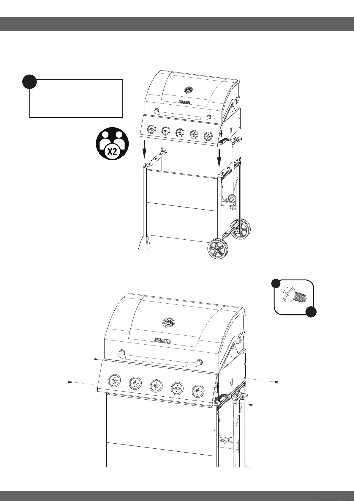
NOTE: During assembly two people will be required to lift the Main Body (1) onto the cart. The Main Body (1)
weighs over 100 lbs.
ASSEMBLY PREPARATION
8
x 4
Phillips Head
Screwdriver
Adjustable
Wrench
Tools required for assembly
Not Included:
Some parts come with
Screws pre-installed.
Loosen and tighten for
nal assembly.
36
39
45
37
46
50
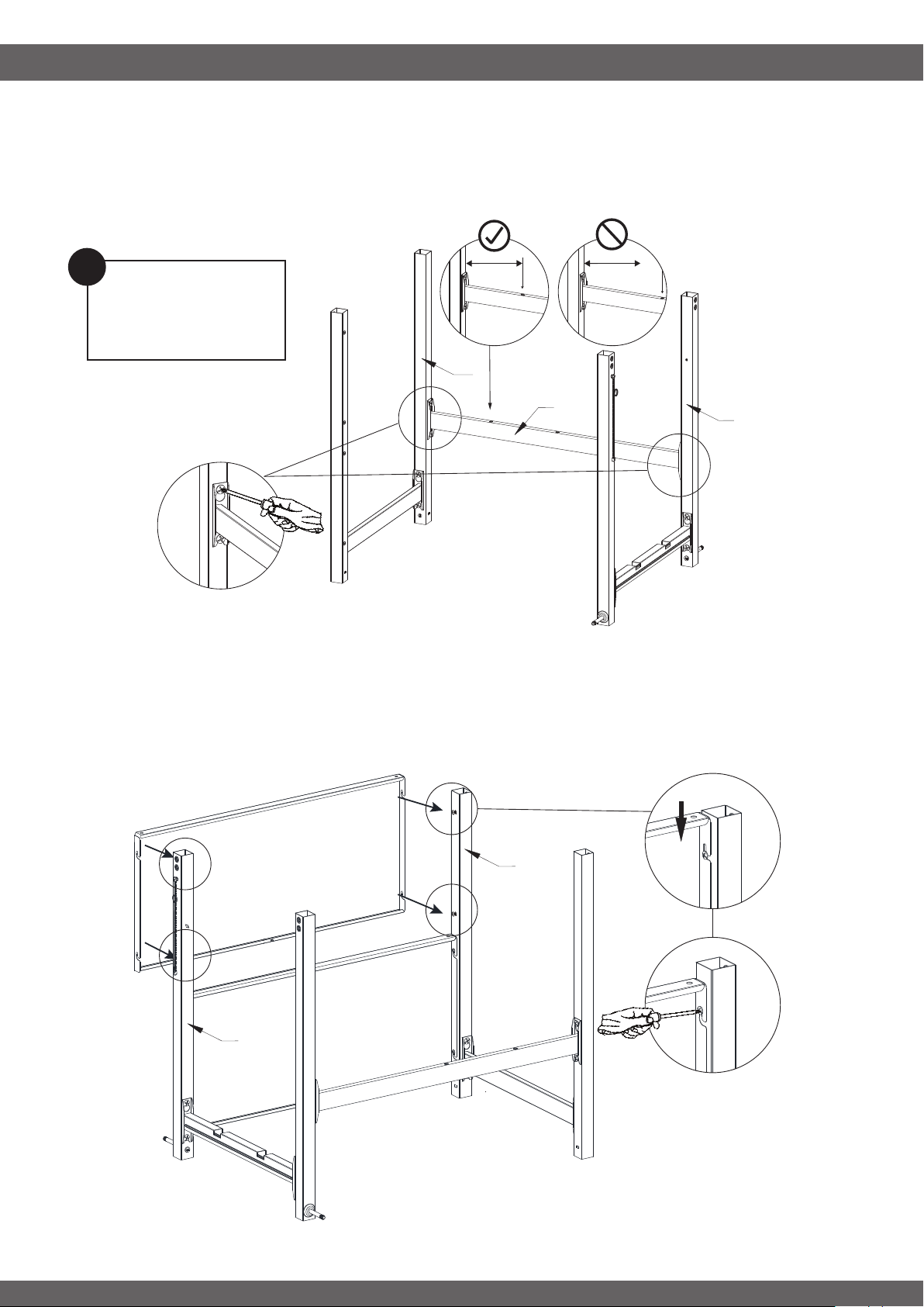
ASSEMBLY INSTRUCTIONS
STEP 2
-----------------------------------------------------------------------------------
• Loosen 4pcs pre-assembled Screws from Left Rear Leg (37) and Right Rear Leg (46), leave the screw
heads protruding approximately 5mm.
• Hang Rear Cart Support Bar (41) to Left Rear Leg (37) and Right Rear Leg (46), then fasten the screws.
9
37
46
41
36
45
42
42
Note: Be sure Rear
Cart Support Bar (41)
is installed properly.
!
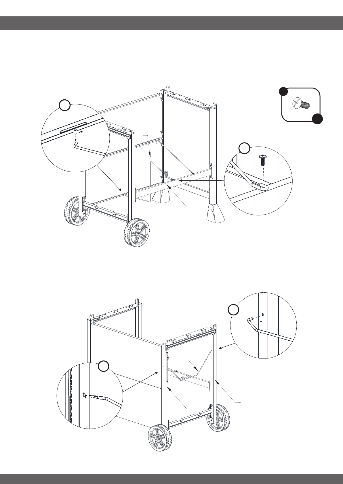
STEP 3
-----------------------------------------------------------------------------------
• Loosen 8pcs pre-assembled Screws from RIght Front (45) and Left Front (36) Legs, leave the screw heads
protruding approximately 5mm.
• 1. Hang the bottom Front Panel (42) to Front legs (45) and (36), then fasten screws.
2. Repeat for the top Front Panel (42)
ASSEMBLY INSTRUCTIONS
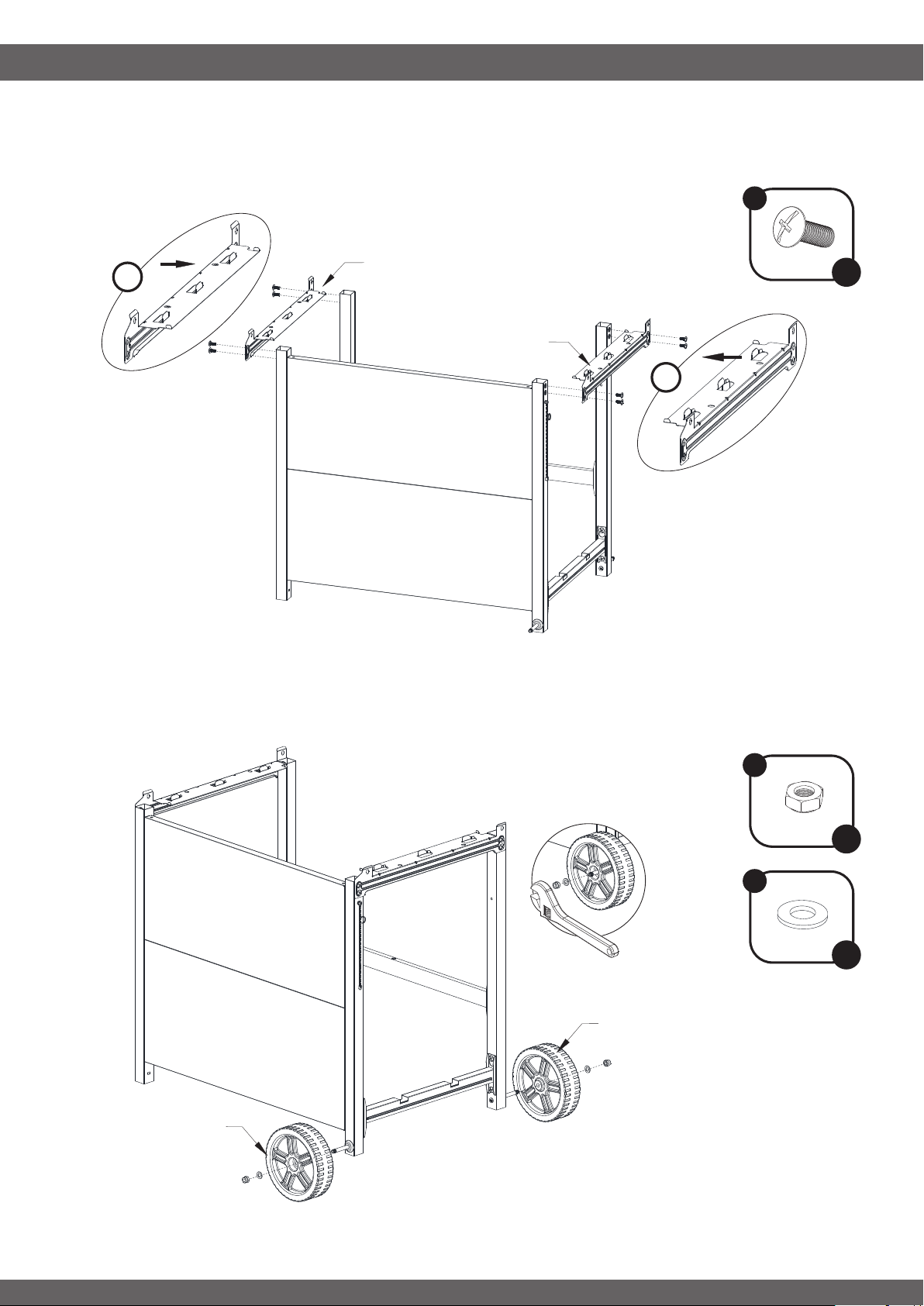
STEP 4
-----------------------------------------------------------------------------------
• Fasten Left Legs Top Support Bar (38) and Right Legs Top Support Bar (47) to legs with 8pcs 1/4-
20X1/2” Screws (A)
STEP 5
-----------------------------------------------------------------------------------
• Place Wheels (51) onto Right Front and Right Back Legs then fasten with wheel nut (E) and washer (D)
10
x 6
D
A
x 8
E
x 2
D
x 2
47
38
L
R
51
51
ASSEMBLY INSTRUCTIONS
STEP 6
-----------------------------------------------------------------------------------
• Attach Plastic Feet (40) to bottom of Left Back and Left Front Legs.
STEP 7
-----------------------------------------------------------------------------------
1. Hook Wire (43) to Front Panel (42)
2. Fasten Wire (43) to Rear Cart Support Bar (41) with 5/32-32 x 3/8” screw (B)
11
B
x 1
40
40
43
41
42
1
2
STEP 9
-----------------------------------------------------------------------------------
1. Hook Gas Tank Holder (48) into Right Rear Leg (46)
2. Key Gas Tank Holder (48) into Right Front Leg (45)
12
ASSEMBLY INSTRUCTIONS
STEP 8
-----------------------------------------------------------------------------------
1. Hook Wire (44) to Front Panel (42)
2. Fasten Wire (44) to Rear Cart Support Bar (41) with 5/32-32 x 3/8” screw (B)
B
x 1
44
41
42
1
2
45
46
1
2
48
13
ASSEMBLY INSTRUCTIONS
STEP 10
-----------------------------------------------------------------------------------
• With the help of another person lower the Fire Box assembly onto leg assembly.
STEP 11
-----------------------------------------------------------------------------------
• Fasten Fire Box to Leg assembly with 4pcs1/4-20X1/2” Screws (A)
A
x 4
Note: Remove zip tie and
other packaging materials
from the gas hose and side
burner valve assembly.
!
STEP 12
-----------------------------------------------------------------------------------
• Fasten pre-assembled screws through Control Panel (23).
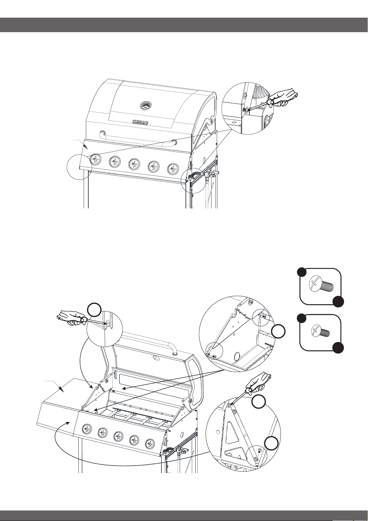
ASSEMBLY INSTRUCTIONS
14
STEP 13
-----------------------------------------------------------------------------------
Loosen the pre-assembled Fire Box Screws and leave the screw heads protruding approximately 5mm.
1. Hang Left Side Table (13) to Fire Box and fasten pre-loosened screws.
2. Fasten 2pcs 1/4-20X1/2” Screws (A) through rebox into Left Side Table (13)
3. Fasten 1pc 5/32-32 x 3/8” Screw (B) through control panel into Left Side Table (13)
23
A
x 2
13
1
1
2
3
B
x 1
ASSEMBLY INSTRUCTIONS
15
STEP 14
-----------------------------------------------------------------------------------
Loosen the pre-assembled Fire Box Screws and leave the screw heads protruding approximately 5mm.
1. Hang Right Side Burner Shelf (27) to Fire Box and fasten pre-loosened screws.
2. Fasten 2pcs 1/4-20X1/2” Screws (A) through rebox into Right Side Burner Shelf (27)
3. Fasten 1pc 5/32-32 x 3/8” Screw (B) through control panel into Right Side Burner Shelf (27)
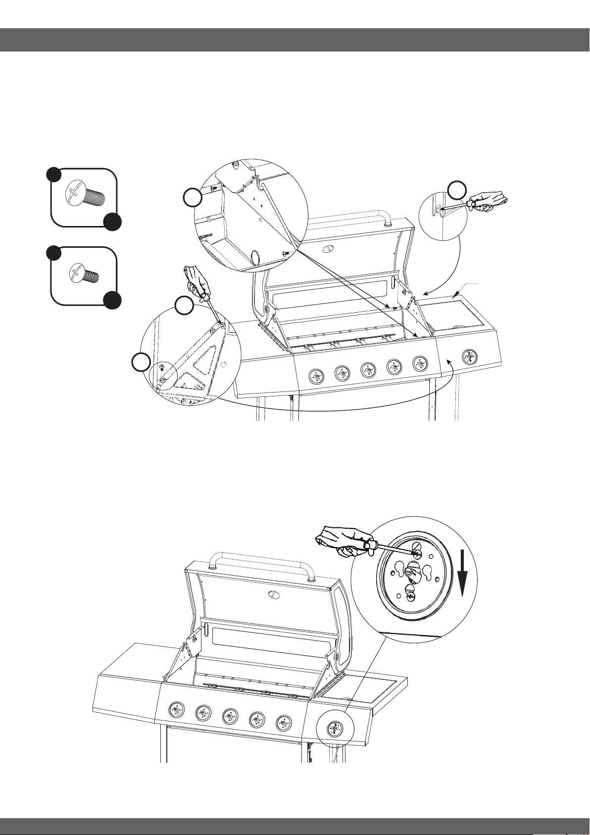
STEP 15
-----------------------------------------------------------------------------------
1. Remove 2 pre-assembled screws from side burner valve assembly.
2. Place side burner valve assembly through the knob bezel and shift the valve down in to place.
3. Secure side burner valve assembly with screws that were previously removed.
A
x 2
B
x 1
1
1
3
2
27
ASSEMBLY INSTRUCTIONS
16
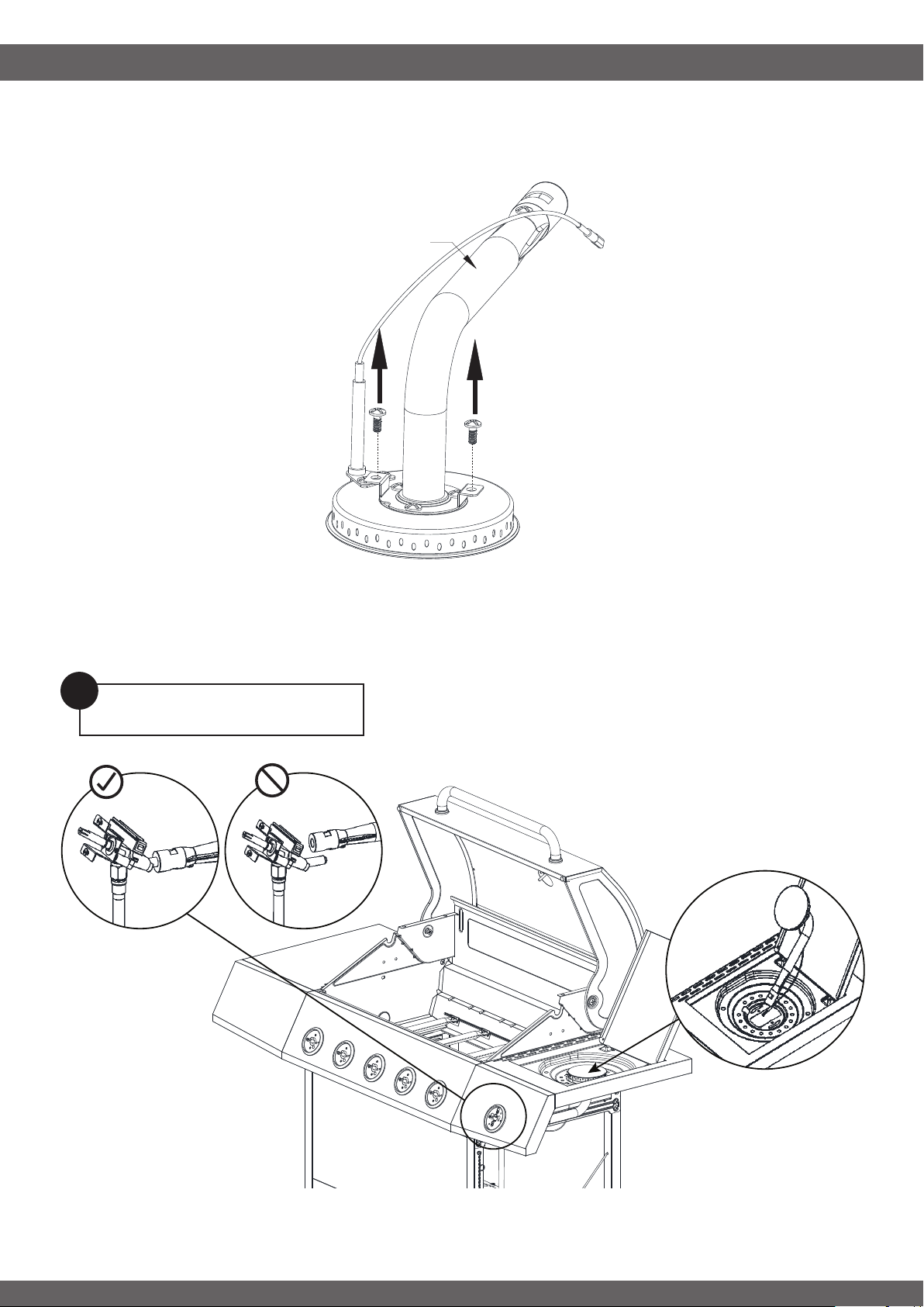
STEP 16
-----------------------------------------------------------------------------------
• Loosen and remove 2pcs pre-assembled screws from Side Burner (31).
31
STEP 17
-----------------------------------------------------------------------------------
• Install Side Burner into Burner Shelf.
• Connect Side Burner to Side Burner Valve assembly.
Note: Be sure Vavle Assembly is
aligned and connected properly.
!
ASSEMBLY INSTRUCTIONS
17
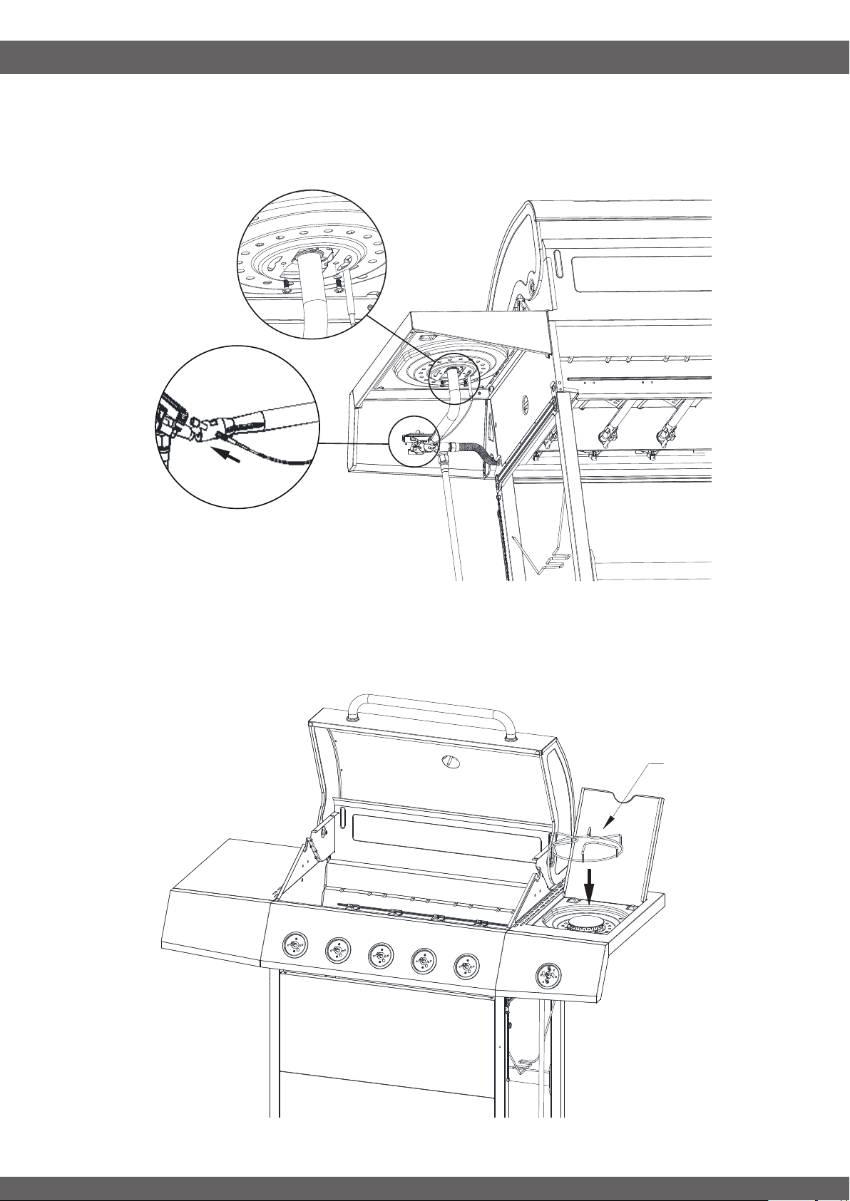
STEP 18
-----------------------------------------------------------------------------------
• Reinstall screws to secure Side Burner to Burner Shelf.
• Connect igniter wire to to side burner valve.
STEP 19
-----------------------------------------------------------------------------------
• Place Side Burner Cooking Grid (28) over side burner.
28
ASSEMBLY INSTRUCTIONS
18
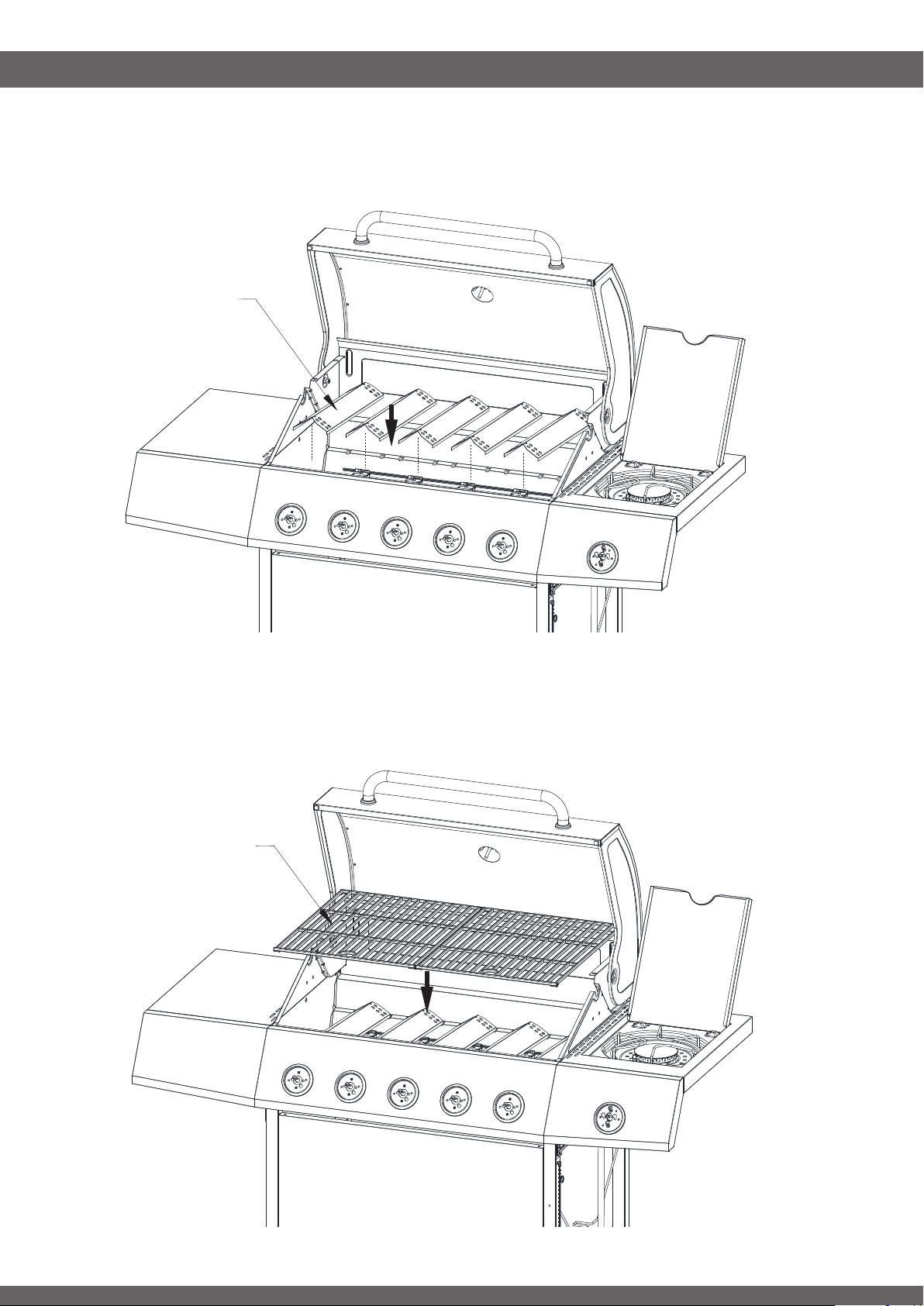
STEP 19
-----------------------------------------------------------------------------------
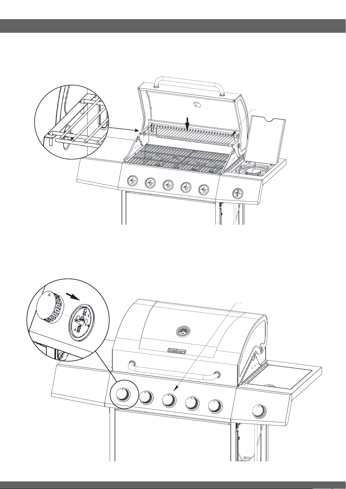
• Install Heat Tents (10) over main burners.
STEP 21
-----------------------------------------------------------------------------------
• Place Cooking Grate (9) over Heat Tents.
10
9
ASSEMBLY INSTRUCTIONS
19
STEP 22
-----------------------------------------------------------------------------------
• Install Warming Rack (8) Cooking Grate.
STEP 23
-----------------------------------------------------------------------------------
• Attach Burner Knobs (25)
8
25
ASSEMBLY INSTRUCTIONS
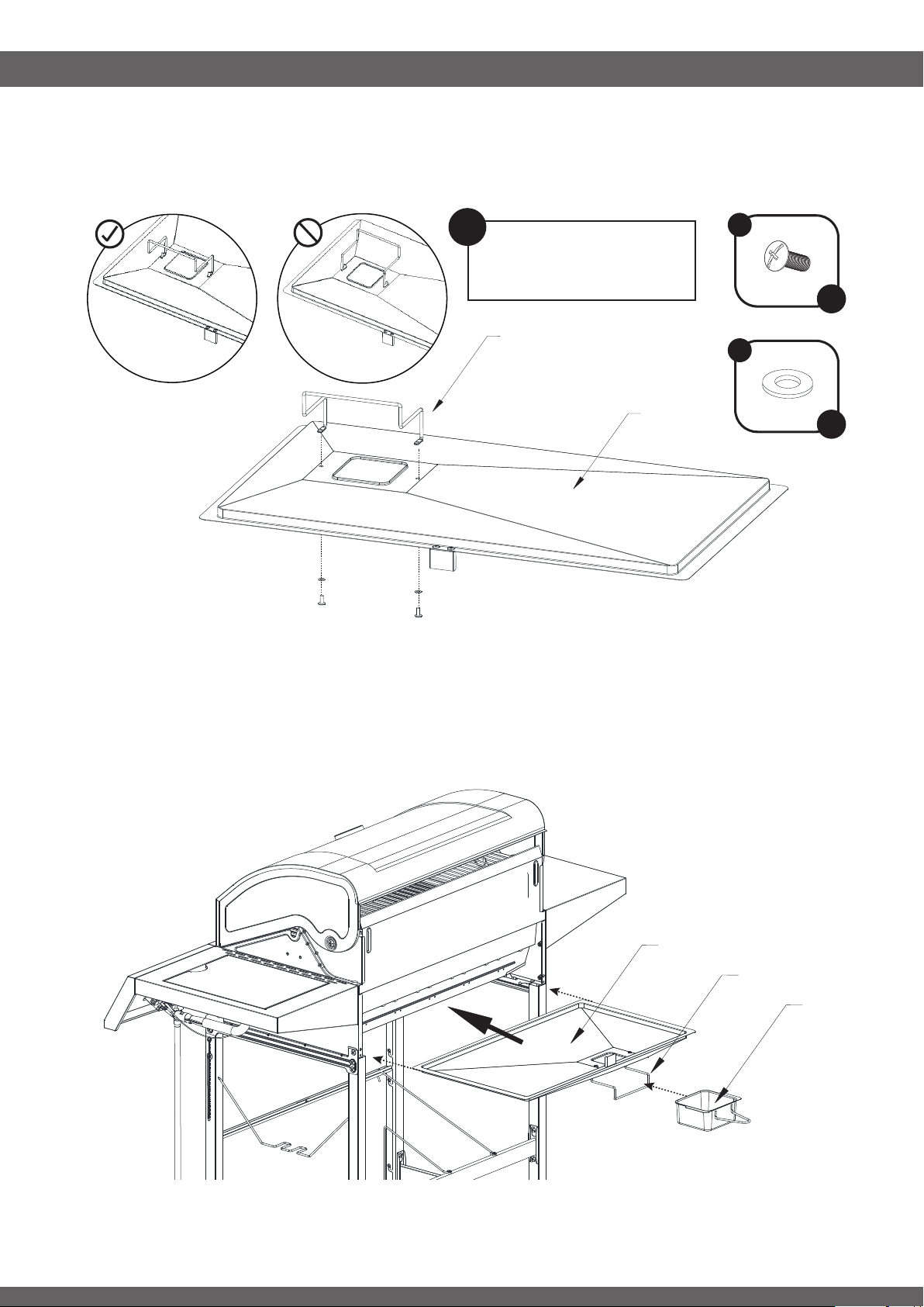
20
STEP 24
-----------------------------------------------------------------------------------
• Install Drip Cup Holder (34) onto under side of Drip Tray (33) using 2pc 5/32-32 x 3/8” srews and washers.
STEP 25
-----------------------------------------------------------------------------------
• Slide Drip Tray (33) into place under Fire Box.
• Slide Drip Cup (35) into Drip Cup Holder (34)
34
33
B
C
x 2
x 2
Note: Be sure Drip Cup
Holder is installed at
proper orientation.
!
34
33
35
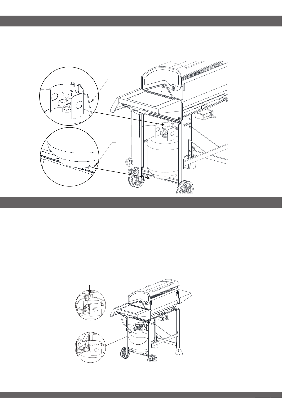
CONNECTING REGULATOR TO THE LP TANK
This Gas grill is set to operate with Liquid Propane Gas come with a high capacity hose and regulator
assembly. (Note: Only use the pressure regulator and hose assembly supplied with the grill or a
replacement pressure regulator and hose assembly specied by the manufacturer).
This assembly is designed to connect directly to a standard 20 lb. L.P. Tank. L.P. tanks are not included with
the grill. L.P. tanks can be purchased separately at an independent dealer.
1. A 20 lb. LP tank must be properly secured onto grill and then put down gas cylinder hook onto the tank.
DO NOT operate the grill if the gas tank is tilted or the hook is placed incorrectly (see Fig. 1)
Fig. 1
Before
After
ASSEMBLY INSTRUCTIONS
21
STEP 26
-----------------------------------------------------------------------------------
• Properly seat tank onto Right Legs Bottom Support Bar (50)
• Attach Gas Tank Holder (48)
48
50
Gas tank must be placed onto the slot on right side beam vertically and be sure the cylinder hook
is placed correctly on the left side collar of the tank (see Fig.3a). DO NOT operate the grill if the
gas tank is tilted or the hook is placed incorrectly (see Fig. 3b)
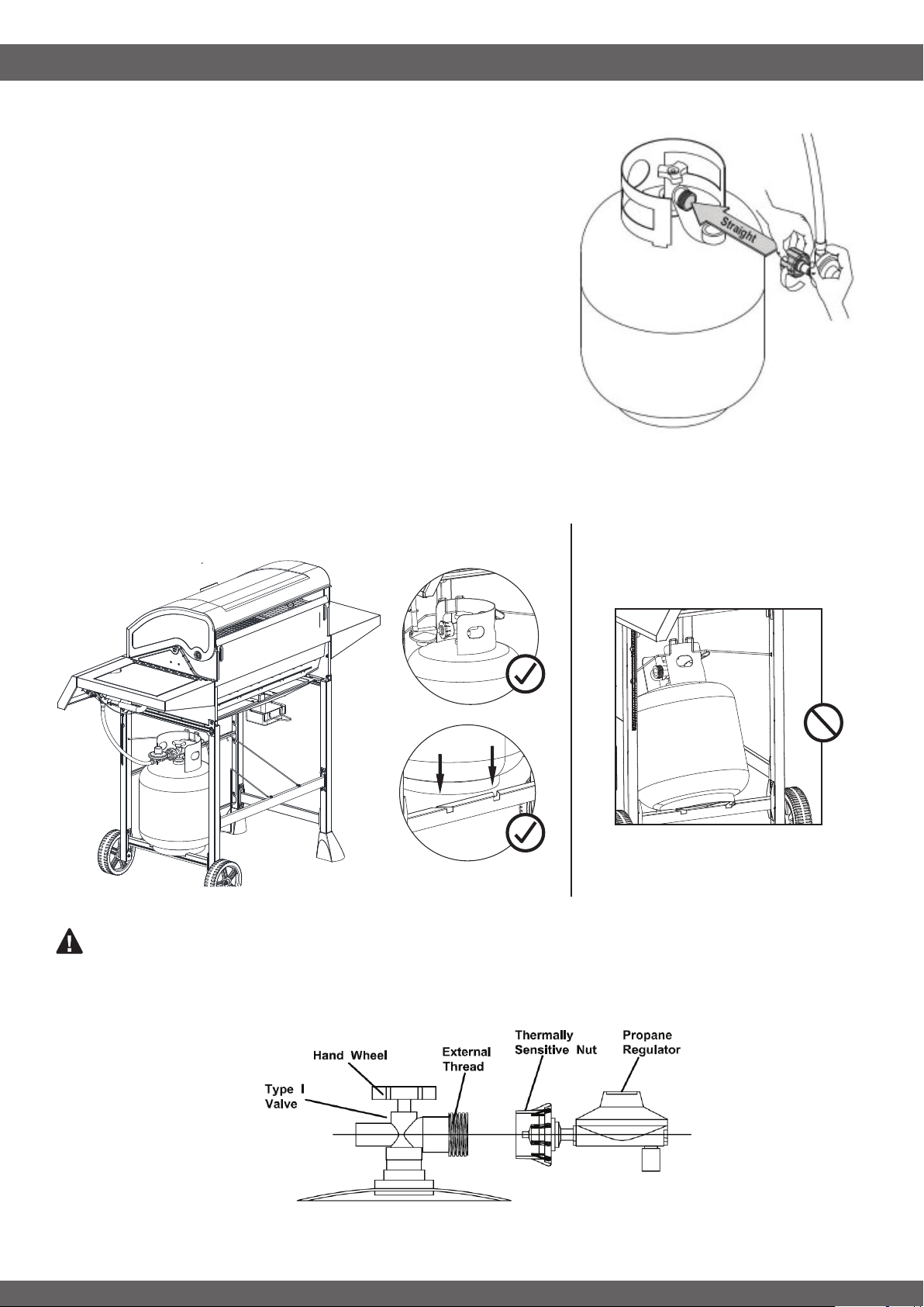
CONNECTING REGULATOR TO THE LP TANK
22
2. Check the tank valve to ensure it has proper external mating
threads to t the hose and regulator assembly provided (Type
1 connection per ANSI Z21.58b-2002).
3. Make sure all burner knobs are in the OFF position.
4. Remove the protective cap from the LP tank valve and
coupling nut. And inspect the valve connection port of the
regulator assembly. Look for damage or debris. Remove any
debris. Inspect hose for damage. Never use damaged or
plugged equipment.
5. Hold regulator by one hand in a straight line with LP tank
valve and insert nipple into LP tank valve. Be sure the nipple is
centered in the valve outlet. (see Fig. 2) Hand-tighten coupling
nut clockwise until it comes to a full stop. DO NOT use tools!
6. Open the tank valve fully (counterclockwise).
7. Perform leak test before attempting to light your grill. See
“CHECKING FOR LEAKS “ on page 20.
Fig. 2
Fig. 3a Fig. 3b
WARNING: The Type I connective coupling (see Fig. 4) supplied with your grill must not be
replaced with a different type of grill/tank connection system. Removal will result in loss of warranty, gas
leakage, re and severe bodily harm.
Fig. 4
CHECKING FOR LEAKS
23
FOR YOUR SAFETY
• Always perform leak tests outdoors ONLY in a
well-ventilated area.
• DO NOT smoke during leak test. DO NOT use
an open ame to check for gas leaks
• Never perform a leak test while the grill is in use
or while grill is still hot.
.
WHEN TO PERFORM A LEAK TEST:
• Every time prior to lighting the grill, even if
purchased fully assembled.
• Repeat Every time the LP gas cylinder is relled
or exchanged.
• Any time your grill has been moved.
• At least once per year or if your grill has not
been used for more than 60 days..
When leak testing this appliance, make sure to test and tighten all loose connections. A slight leak in the
system can result in a low ame or hazardous condition. Most L.P. gas tanks now come equipped with a leak
detector mechanism internal to the tank. When gas is allowed to escape rapidly, it shuts off the gas supply. A
leak may signicantly reduce the gas ow, making the grill difcult to light or causing low ames.
DANGER
WARNING
WARNING
Perfom Leak Test
-----------------------------------------------------------------------------------
Although all gas connections on the grill are leak tested prior to shipment, a complete gas tightness check
must be performed at the installation site due to possible shifts during shipment, installation or excessive
pressure unknowingly being applied to the unit. Periodically check the whole system for leaks and immediately
check the system if the smell of gas is detected.
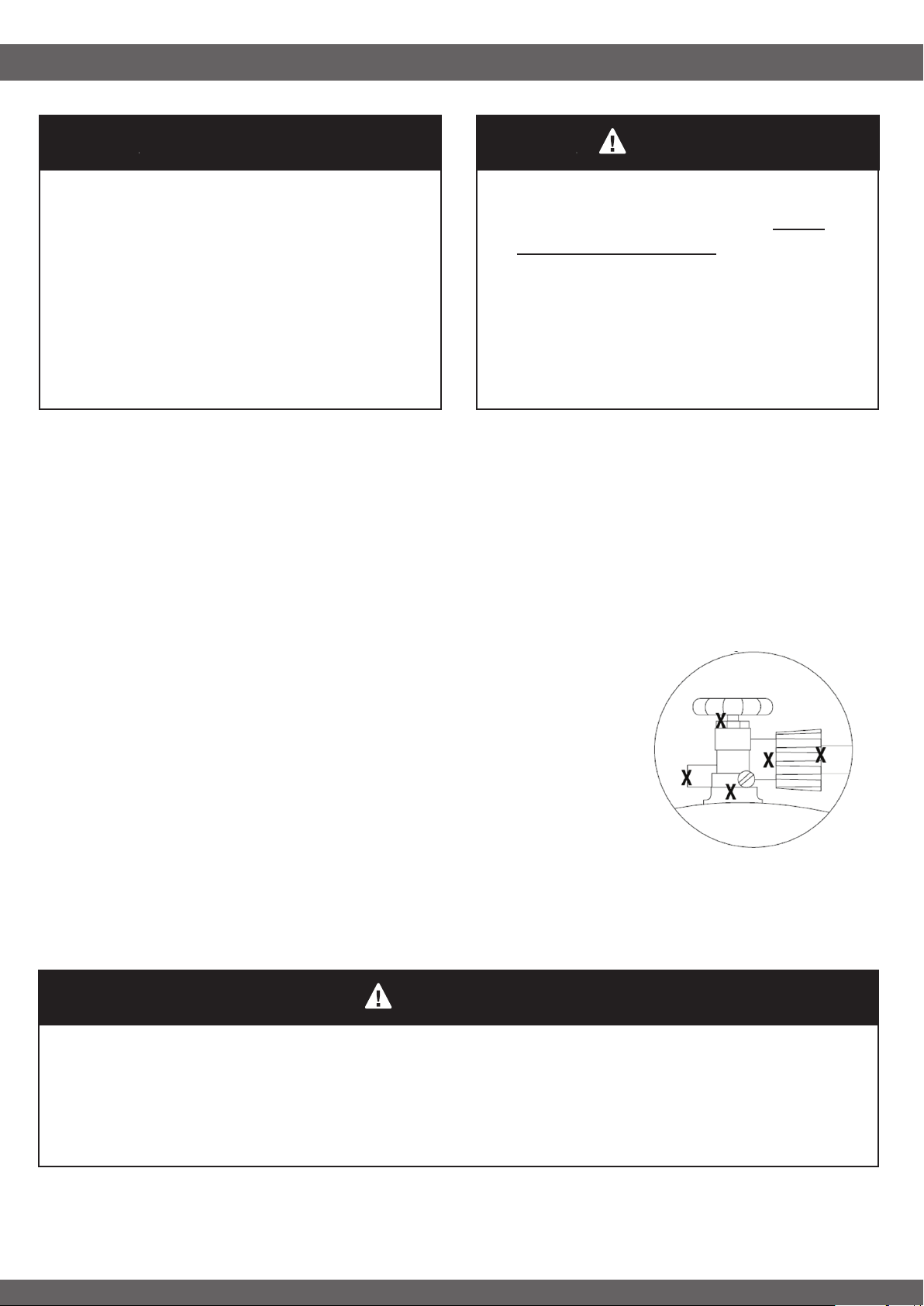
1. Create a mixture of 50% water and 50% liquid dishwashing soap.
2. Ensure all control knobs are set to the “OFF” position.
3. Turn ON LP gas tank at valve.
4. Brush soapy solution at all ”X” locations (see Fig.5).
5. Check each place for growing bubbles If “growing” bubbles appear,
turn the Tank Valve off and DO NOT use your grill until the leak is
repaired. A slight leak could cause a re. If no bubbles appear after
one minute, turn tank OFF, wash off soapy solution with cold water and
towel dry.
Fig. 5
LP TANK INFORMATION
LP TANK USE
24
DO NOT store a spare L.P. gas tank under or
near the grill. Never ll the cylinder beyond
80% full.
If this information is not followed exactly, a
re causing death or serious injury may occur.
WARNING
Never use a dented or rusted L.P. tank or cylinder with a damaged valve.
L.P. cylinders are equipped with an O.P.D. (Overlling Prevention Device). The device shuts off the ow
of gas to a cylinder after 80% capacity is reached. This limits the potential for release of gas when the
cylinder is heated, averting a re or possible injury.
The L.P. cylinder must have a shut-off valve terminating in an L.P. gas supply cylinder outlet specied, as
applicable, for connection No. 510 in the standard for compressed gas cylinder valve outlet and inlet
connection ANSI/CGA-V-1. Cylinders must not be stored in a building, garage, or any other enclosed
area. (The L.P. cylinder must have an overll protection device and a collar to protect the cylinder
valve.)
The L.P. gas supply cylinder must be constructed and marked in accordance with the specications for
L.P. gas cylinders of the U.S. Department of Transportation (DOT) or the National Standard of Canada,
CAN/CAS-B339, “Cylinders, Spheres and Tubes for the Transportation of Dangerous Goods and
Commission.”
When turning the L.P. tank on, make sure to open the valve SLOWLY two (2) complete turns to ensure
proper gas ow. Most gas tanks now come equipped with a leak detector mechanism internal to the
tank. When gas is allowed to escape rapidly it shuts off the gas supply. Opening the valve rapidly may
simulate a gas leak, causing the safety device to activate, and restricting gas ow causing low ames.
Opening the valve slowly will ensure this safety feature is not falsely triggered.
• When not in use, gas supply cylinder valve is to be in the OFF position.
• Storage of an outdoor gas cooking appliance indoor is permissible only if the cylinder is disconnected and
removed from the appliance.
• The tank supply system must be stored upright to allow for vapor withdrawal.
• The regulator and hose assembly must be inspected before each use of the grill. If there is excessive
abrasion or wear or if the hose is cut, it must be replaced prior to the grill being used again.
• Cylinders must be stored outdoors out of the
reach of children and must not be stored in a
building garage or any other enclosed area.
• Place dust cap on cylinder valve outlet
whenever the cylinder is not in use. Only
install the type of dust cap on the cylinder
valve outlet that is provided with the cylinder
valve. Other types of caps or plugs may
result in leakage of propane.
• Only a qualied gas supplier should rell the
L.P. tank.
LIGHTING INSTRUCTIONS
25
-----------------------------------
WARNING
----------------------------------
DO NOT lean over grill when lighting.
Turn off Gas supply when appliance is not in use.
DO NOT stand with head, body, or arms over the grill when lighting
-----------------------------------------------------------------------------------
Lighting Instructions
-----------------------------------------------------------------------------------
1. Check the control knobs are all in the OFF position.
2. Open LP cylinder valve.
3. Open lid before lighting.
4. Push and turn the knob slowly to HIGH. The burner should ignite within three attempts.
5. If burner does not ignite, turn the knob to OFF, wait 5 minute and then repeat step 4.
6. Once burner is lit, rotate knob to desired heating level from High to Low
7. If the ignitor does not work, follow Match Lighting instructions.
8. To turn off, turn the knob to HIGH rst, then push in and turn to OFF position. Turn off the gas tank valve
before disconnecting the LP gas tank.
Match Lighting
-----------------------------------------------------------------------------------
1. Open lid before lighting
2. Place a match in the end of Match Holder (hanging on the Right Front Leg). Strike the match and place it
near side of the burner (see Fig.6)
3. Push and turn the control knob to HIGH. The burner should ignite.
NOTE: If the burner does not ignite within the rst few attempts of match lighting, there is a problem with the
gas supply. Turn off the gas at the burner and tank. DO NOT attempt to operate the grill until the problem is
found and corrected. See “Trouble Shooting” section of this manual or call the customer service department
at 1-866-994-6390 from 9:00am to 5:00pm Eastern time, Monday through Friday for assistance.
Fig. 6
CARE AND MAINTENANCE
26
• We highly recommend this gas grill be thoroughly inspected and serviced annually by a qualied service
person.
• It is recommended that you always check that the outdoor cooking appliance area is clear and free from
combustible material, gasoline and other ammable vapors and liquids before lighting.
• It is recommended that you regularly check that the ventilation openings of the grill cabinet are free and
clear from debris.
• It is recommended that you regularly check and clean the burner/venturi tubes for insects and insect
nests. A clogged tube can lead to a re beneath the grill.
• It is recommended that you regularly check that the ow of combustion and ventilation air is not
obstructed.
Recommended Cleaning Supplies
-----------------------------------------------------------------------------------
Mild liquid dish soap, warm water, nylon cleaning pad, wire brush.
DO NOT use cleaners that contain acid, mineral spirits or any abrasive substance.
Outside Surfaces
-----------------------------------------------------------------------------------
Only use mild dish soap and hot water to clean grill and grill parts. Rinse with warm water.
Drip Tray
-----------------------------------------------------------------------------------
The drip tray should be kept clean on a regular basis to prevent heavy buildup of debris. Accumulated grease
is a re hazard.
Important: DO NOT leave the grill outside during inclement weather unless it is covered. Rain water can
collect inside of the grill, the grill cart or the drip tray if left uncovered. If the drip tray is not cleaned after use
and the grill is left uncovered, the drip tray will ll with water causing grease and water to spill into the grill cart.
Ensure the grill is cool before cleaning and conducting maintenance and with the gas supply turned
off at the LP-Gas Cylinder.
To avoid the possibility of burns, maintenance should be done only when the grill is cool.
Avoid unprotected contact with hot surfaces.
A leak test must be performed annually and whenever any component of the gas train is replaced or
gas smell is present.
For your safety, always wear protective gloves and safety glasses when cleaning your grill.
WARNING

CARE AND MAINTENANCE
27
Cooking Grates
--------------------------------------------------------------------------------
To ‘burn off’ or heat clean your grill, turn the burners to highest position and run for 15 minutes with the lid
closed. Then turn off the burners and use a wire brush to clean excess food residue from the grates.
Stainles Steel
-----------------------------------------------------------------------------------
After initial usage, areas of the grill may discolor from the intense heat given off by the burners. This is normal.
Purchase a mild stainless steel cleaner and rub in the direction of the grain of the metal. Specks of grease
can gather on the surface of the stainless steel and bake on to the surface and give a worn appearance. For
removal, use a non-abrasive oven cleaner in conjunction with a stainless cleaner.
NOTE: Always scrub in the direction of the grain.
Painted Surfaces
-----------------------------------------------------------------------------------
Wash with mild detergent or nonabrasive cleaner and warm soapy water. Wipe dry with a soft nonabrasive
cloth
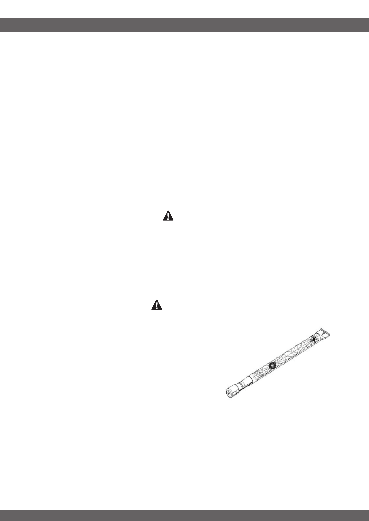
Porcelain Parts
-----------------------------------------------------------------------------------
Certain parts of your grill have a porcelain coating. Porcelain is a glass-based product and is highly durable
to standard wear and tear. However, porcelain is sensitive to concussive blows, which can create interlaced
micro-fractures or “spider-webs.” Please take care not to strike any porcelain covered parts with solid objects,
drop them, or create any other concussive blows. These interlaced micro-fractures are common and may lead
to minor chipping. Neither the chipping nor the interlaced micro-fractures will adversely affect the performance
of your grill and are not covered under the warranty for porcelain parts.
Ignitor
-----------------------------------------------------------------------------------
You must take some actions to prevent cracking of the burner’s ceramic ignitor surfaces, which will cause the
burners to malfunction. Damage caused by failure to follow these steps is not covered by your grill warranty.
IMPACT WITH HARD OBJECTS - Never allow hard objects to strike the ceramic ignitor. You should take
particular care when inserting or removing cooking grids and accessories into or from the grill. If objects such
as these fall onto ceramic ignitor, it is likely to crack the ceramic.
IMPAIRED VENTILATION OF HOT AIR FROM GRILL - In order for the burners to function properly, hot air
created by the burners must have a way to escape. The burners may become deprived of oxygen, causing
them to backre, especially if the burner output is set at HIGH. If this occurs repeatedly, the burners may
crack. This is the reason your grill was designed with ventilation louvers. These design features give the hot air
an escape route. Accordingly, never operate your grill with very little or no open space at the cooking surface
(the cooking grids provide sufcient space). Also, DO NOT cover the entire surface with foil, a large pan, etc.
CARE AND MAINTENANCE
28
Storage
--------------------------------------------------------------------------------
• Ensure the grill is properly cooled.
• Storage of this gas grill indoors is permissible only if the gas cylinder is disconnected and removed from
the grill.
• Store the grill in a cool dry place.
• Always disconnect the gas cylinder and store it in a safe place, never store a gas cylinder on its side.
• Never store a gas cylinder in a building, garage or any other enclosed area.
• If you intend to leave your grill outside make sure it is protected from the elements by a heavy-duty cover
(not included).
• Keep outdoor cooking gas grill area clear and free form combustible materials, gasoline and other
ammable vapors and liquids.
• Although the grill is manufactured from quality materials, including some parts manufactured from stainless
steel, storage out in the open may result in corrosion of some exterior surfaces or components. We
recommend you protect your grill from the weather by covering it with a grill cover, tarp, or other protective
material or device.
• In addition, a commercial stainless steel cleaner or wipe will keep the stainless steel components maintain
their as-new appearance.
-----------------------------------
WARNING
----------------------------------
Clean grill in an area where cleaning solutions will not harm decks, lawns, or patios.
----------------------------------------------------------------------------------
DO NOT use oven cleaner to clean any part of this gas grill. DO NOT use a self-cleaning oven to clean
cooking grids or any other parts of the gas grill. Barbecue sauce and salt can be corrosive and will cause
rapid deterioration of the gas grill components unless cleaned regularly.
--------------------------------
SPIDER ALERT
---------------------------------
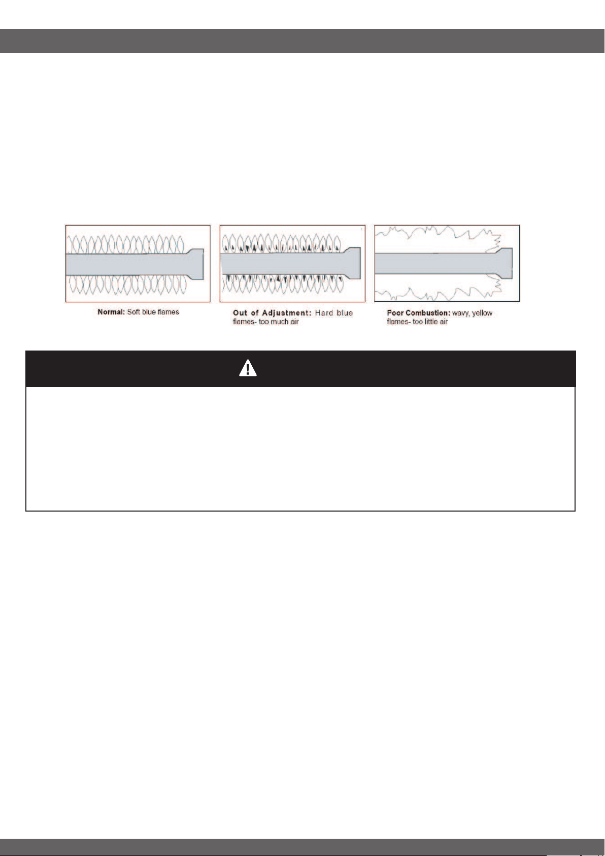
SPIDER AND WEBS INSIDE BURNER TUBE
Spiders or small insects have been known to create
ashback problems. The spiders spin webs, build nests and
lay eggs in the grill’s burner tubes obstructing the ow of
gas to the burner. The backed-up gas can ignite in the
burner tube behind the control panel. This is known as a
ashback and it can lead to a re and even cause injury.
If you notice that your grill is getting hard to light or that the
ame isn’t as strong as it should be, take the time to check
and clean the burner tubes.
29
CARE AND MAINTENANCE
Cleaning Main Burner
--------------------------------------------------------------------------------
To prevent Flash backs and good performance of burner, the procedure below should be followed at
least once a month in late summer or early fall when spiders are most active or when your grill has
not been used for a period of time:
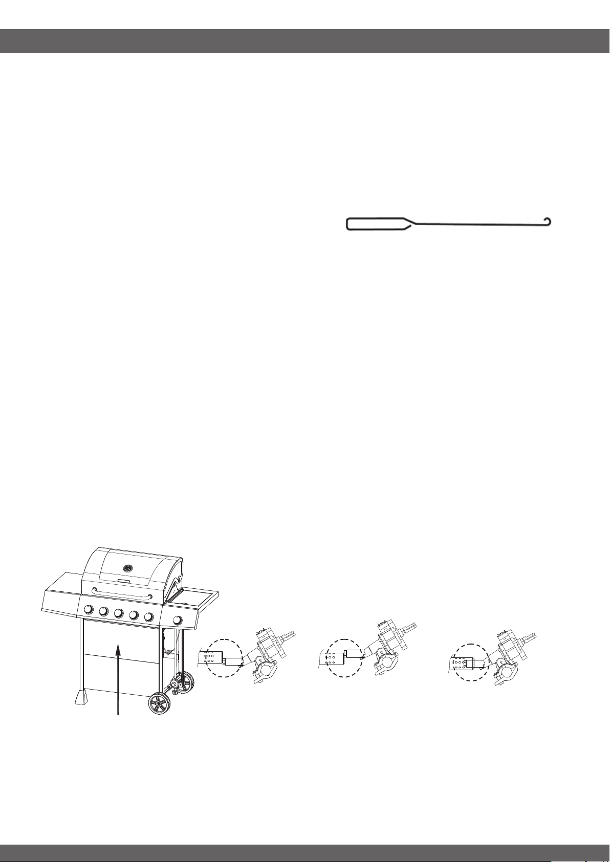
1. Turn off at control knobs and LP cylinder.
2. Remove cooking grates and ame tamers
3. Remove cotter pins from rear of burners. Detach ignition wire from the ignition pin by hand only. DO NOT
use tool. Then Lift burner slowly.
4. Check all burner ports are clear of clogs. Use of
a pin or paper clip works well.
5. Ensure the end of the burner and primary
air screen are clear from insect nests, dirt or
debris. Using a bent stiff wire in the shape of a hook , or a bottle brush, run it through the burner tube and
inside several times to remove any debris.
6. Inspect each burner for damage (cracks or holes) and if such damage is found, order and install a new
burner.
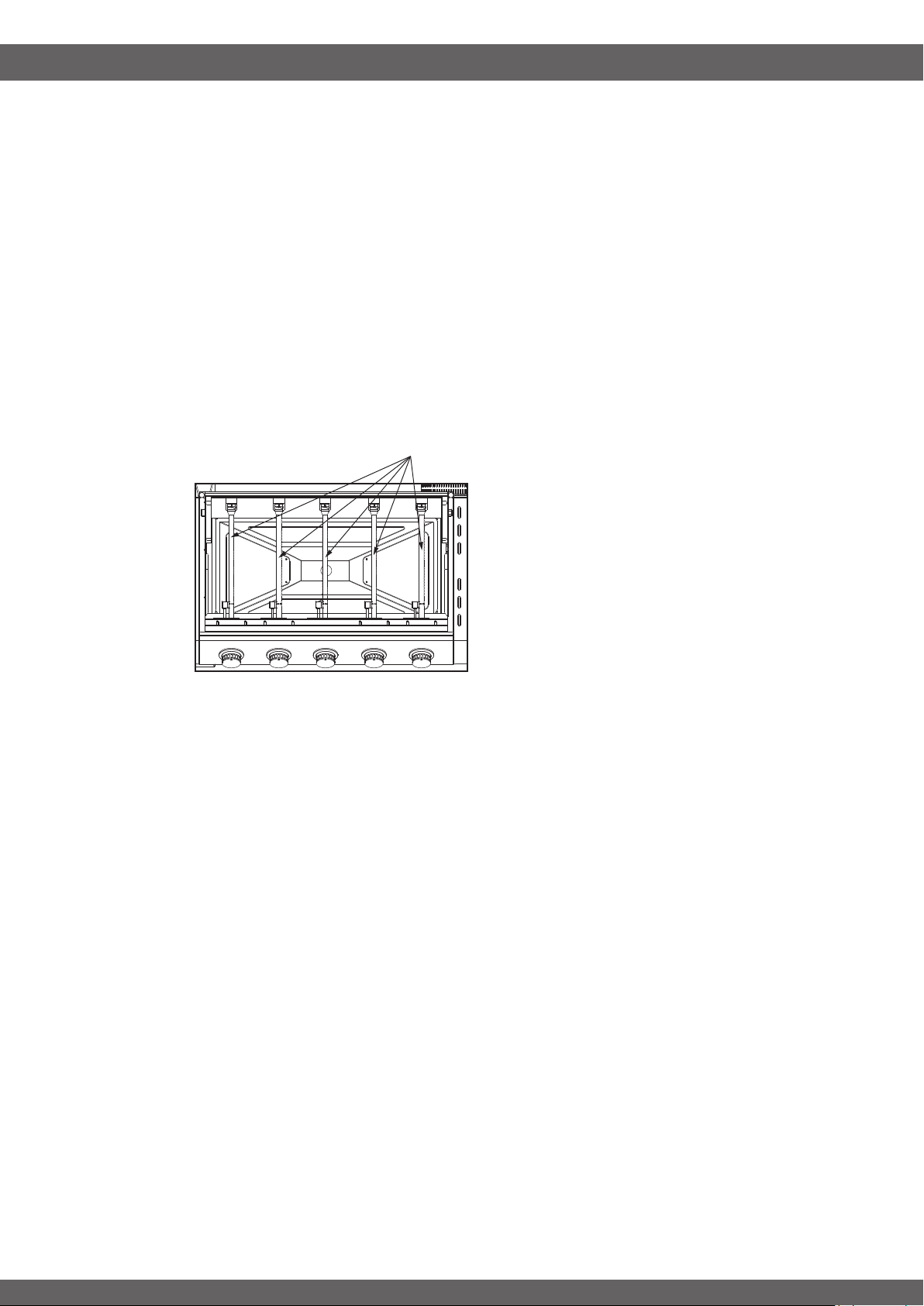
Re-Installing Main Burners
-----------------------------------------------------------------------------------
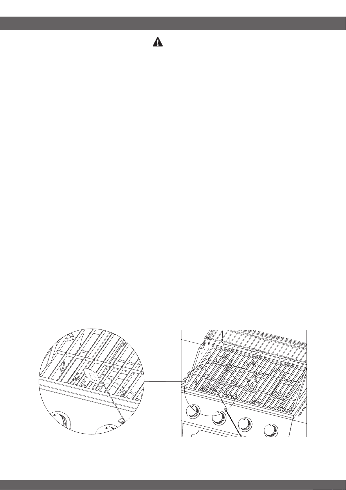
Ensure the gas valve orices must be correctly positioned inside the burner tube. If the burner tube
does not t over the valve orice, lighting the burner may cause explosion and/or re.
It is recommended to use a ashlight to view the correct position through the rebox vent holes as
illustrated below.
After checking , reattach each burner with the cotter pins and reattach the ignition wire to the ignition
pin by hand.
Wrong
Wrong
Correct
View the correct position
from the bottom of the firebox
30
TROUBLE SHOOTING
ISSUE RESOLUTION:
-----------------------------------------------------------------------------------
Many solutions given here can make your grilling experience safer and more enjoyable. You can also call
customer service department at 1 866 994 6390 from 9:00am to 5:00pm Eastern time, Monday through
Friday for assistance.
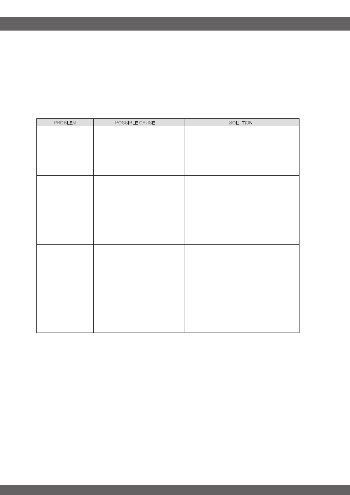
PROBLEM POSSIBLE CAUSE SOLUTION
Grill will not light.
1. The ignition wire came off the
igniter/valve.
2. The distance between the ignition pin
and the burner is greater than 5/32 in. -
3/16 in.
3. The ignition wire is broken.
4. No gas supplied.
1. Reconnect the ignition wire to the electrical
igniter/valve.
2. Loosen the ignition pin and adjust the distance,
then fasten it again.
3. Call customer service for a replacement ignition
wire.
4. Turn on the regulator valve.
Flashback
(re in burner tube(s))
Burner and/or burner tubes are blocked
Turn knobs to OFF. Clean burner and/or burner
tubes. See burner cleaning
section of Use and Care.
Excessive are-up.
1. Grease and/or residue build-up on
heat tents or in rebox.
2. Excessive dripping of fat or marinade
from food.
3. Cooking temperature too high.
1. Clean the grill components.
2. Trim the fat from meat and use non-oil based
marinades.
3. Lower temperature accordingly
Sudden drop in gas ow
or low ame
1. Out of gas
2. Excess ow valve tripped.
3. Vapor lock at coupling nut/LP cylinder
connection
1. Check for gas in LP cylinder.
2. Turn off knobs, wait 30 seconds and light grill. If
ames are still low, turn off knobs
and LP cylinder valve. Disconnect regulator.
Reconnect regulator and leak-test. Turn on LP
cylinder valve, wait 30 seconds and then light grill.
3. Turn off knobs and LP cylinder valve. Disconnect
coupling nut from cylinder. Reconnect and retry.
Persistent grease re
Grease trapped by food buildup around
burner system.
Turn knobs to OFF. Turn gas off at LP cylinder.
Leave lid in position and let re out. After grill cools,
remove and clean all parts.
31
WARRANTY
PROOF OF PURCHASE
-----------------------------------------------------------------------------------
Proof of purchase is required to access this warranty program, which is in effect from the date of
purchase. Customers will be subject to parts, shipping, and handling fees if unable to provide proof of
the purchase or after the warranty has expired.
If you have any questions or problems, you can call our customer service department at 1-866-994-6390
from 9:00am to 5:00pm Eastern time, Monday through Friday for assistance.
LIMITED WARRANTY
-----------------------------------------------------------------------------------
Manufacturer warrants this product for the Stainless Steel Main Burner for 3 years and all other
replacement parts for 1 years from the date of purchase.
WARRANTY PROVISIONS
-----------------------------------------------------------------------------------
This warranty is non-transferable and does not cover failures due to misuse of improper installation or
maintenance.
This warranty is for replacement of defective parts only. We are not responsible for incidental or
consequential damages or labor costs.
This warranty does not cover corrosion or discoloration after the grill is used, or lack of maintenance,
hostile environment, accidents, alterations, abuse or neglect.
This warranty does not cover damage caused by heat, abrasive and chemical cleaners, or any damage to
other components used in the installation or operation of the gas grill.
Paint is not warranted and may require touch-up. Items considered to be consumable such as batteries
are not covered under this warranty.
Some states DO NOT allow the limitation or exclusion of incidental or consequential damages, so the
above limitations or exclusions may not apply to you. This warranty gives you specic legal rights, and
you may also have other rights that vary from state to state.
For replacement parts, call our customer service department at 1-866-994-6390 from 9:00am to
5:00pm Eastern time, Monday through Friday for assistance.
Stainless Steel Main Burner