Loading ...
Loading ...
Loading ...
• Models 820-829 only: Place the speed control
lever in the first position.
• Models 840-849 only: Place the speed control
lever in the second position.
• Disconnect the front speed control link from the
variable speed torque bracket by removing the
cotter pin and flat washer.
• Place a 3/4" shim or other suitable object under the
point on the bracket on the clutch-brake pedal as
shown in Figure 21.
• Thread the front speed control link in or out of the
ferrule until the hole in the link lines up with the pin
on the variable speed torque bracket. Secure with
the flat washer and cotter pin removed earlier.
• Push the rear speed control link backward using
light pressure, and hold itin this position as you
thread it into or out of the ferrule until the hole in the
link lines up with the pin on the variable speed
torque bracket.
• Models 820-829 only: Turn the link three more
times making it longer.
• Move the speed control lever toward the right so
that the hole in rear speed control link fits over the
pin on the variable speed torque bracket. Secure
with the flat washer and cotter pin removed earlier.
• Remove the 3/4" shim from beneath the bracket on
the clutch-brake pedal.
QuickAdjustmentSeat
• To adjust the position of the seat, move the seat
adjustment lever (located under the seat) to the left
and slide the seat forward or backwards. See
Figure 22. Make sure seat is locked into one of the
six adjustment positions before operating the
garden tractor.
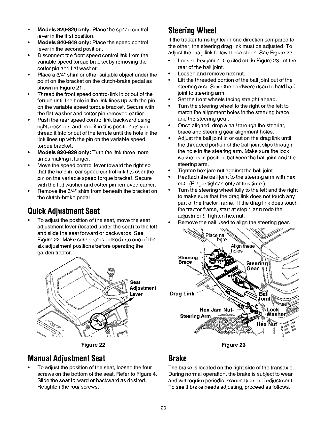
SteeringWheel
If the tractor turns tighter in one direction compared to
the other, the steering drag link must be adjusted. To
adjust the drag link follow these steps. See Figure 23.
• Loosen hex jam nut, called out in Figure 23, at the
rear of the ball joint.
• Loosen and remove hex nut.
• Lift the threaded portion of the ball joint out of the
steering arm. Save the hardware used to hold ball
joint to steering arm.
• Set the front wheels facing straight ahead.
• Turn the steering wheel to the right or the left to
match the alignment holes in the steering brace
and the steering gear.
• Once aligned, drop a nail through the steering
brace and steering gear alignment holes.
• Adjust the ball joint in or out on the drag link until
the threaded portion of the ball joint slips through
the hole in the steering arm. Make sure the lock
washer is in position between the ball joint and the
steering arm.
• Tighten hex jam nut against the ball joint.
• Reattach the ball joint to the steering arm with hex
nut. (Finger tighten only at thistime.)
• Turn the steering wheel fully to the left and the right
to make sure that the drag link does not touch any
part of the tractor frame. Ifthe drag link does touch
the tractor frame, start at step 1 and redo the
adjustment. Tighten hex nut.
• Remove the nail used to align the steering gear.
Steering
Brace
!!;Seat
Adjustment
Lever Drag Link
Hex Jam
Figure 22
ManualAdjustmentSeat
• To adjust the position of the seat, loosen the four
screws on the bottom of the seat. Refer to Figure 4.
Slide the seat forward or backward as desired.
Retighten the four screws.
Figure 23
Brake
The brake is located on the right side of the transaxle.
During normal operation, the brake is subject to wear
and will require periodic examination and adjustment.
To see if brake needs adjusting, proceed as follows.
2O
Loading ...
Loading ...
Loading ...