Loading ...
Loading ...
Loading ...
• Remove the four screws which secure the seat to
the seat pivot bracket.
NOTE: If the seat was shipped in a box, remove four
screws from the bottom of the seat and place the seat in
position against the seat pivot bracket.
Turn the seat around and place in position against
the seat pivot bracket, lining up the slotted holes in
the pivot bracket with the holes in the seat. Select
desired position for the seat, and secure with the
four screws. See Figure 4.
QuickAdjustmentSeat
Seat Pivot
Bracket_)
Figure 5
• Pull out tab on seat stop and hold open while sliding
seat out of seat pivot bracket. See Figure 5.
• Turn the seat around and line up plastic seat
spacers with the slots in seat pivot bracket.
• Slide seat in until front seat spacer engages the
seat stop. See Figure 6. To adjust the seat refer to
the adjustment section in this manual.
Seat
Spacers
Figure 6
NOTE: If the seat was shipped in a box, fine up plastic
seat spacers with the slots in seat pivot bracket and
slide seat in until front seat spacer engages seat stop.
,_ WARNING: Quick adjustment seat only:Before operating tractor, stand behind the seat
and pull back on it to make sure the seat is
engaged in the seat stop.
AttachingDeckLinks
(Hardware A)
The three adjustable deck links have been shipped
unassembled. Attach as follows.
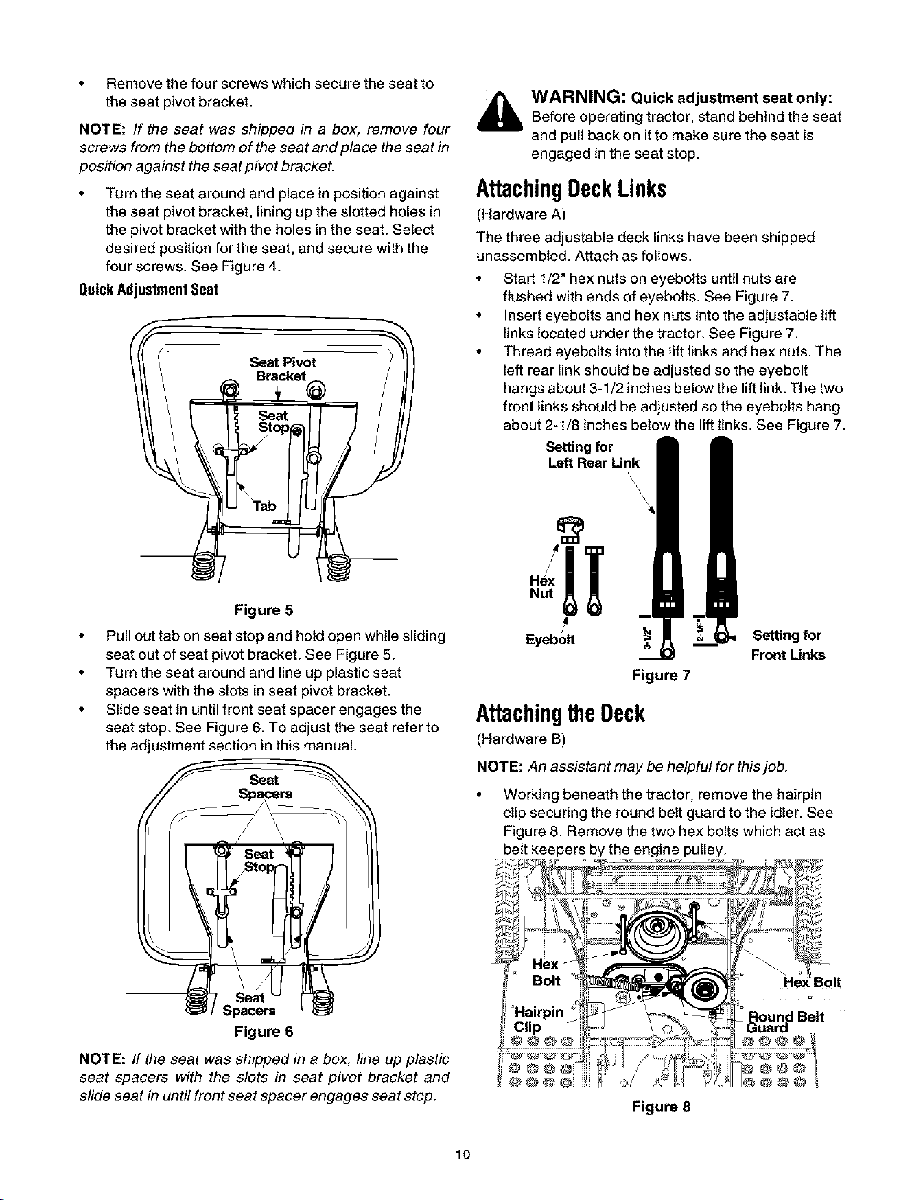
• Start 1/2" hex nuts on eyebolts until nuts are
flushed with ends of eyebolts. See Figure 7.
• Insert eyebolts and hex nuts intothe adjustable lift
links located under the tractor. See Figure 7.
• Thread eyebolts into the lift links and hex nuts. The
left rear link should be adjusted so the eyebolt
hangs about 3-1/2 inches below the lift link. The two
front links should be adjusted so the eyebolts hang
about 2-1/8 inches below the lift links. See Figure 7.
Settingfor
Left Rear Link
\
\
\
Eyebolt
Front Unks
Figure 7
AttachingtheDeck
(Hardware B)
NOTE: An assistant may be helpful for this job.
Working beneath the tractor, remove the hairpin
clip securing the round belt guard to the idler. See
Figure 8. Remove the two hex bolts which act as
belt keepers by the engine pulley.
Figure 8
Bolt
I Belt
@@@
10
Loading ...
Loading ...
Loading ...