Loading ...
Loading ...
Loading ...
Tire Pressure
The tires on your tractor may be over-inflated for
shipping purposes. Reduce the tire pressure before
operating the unit. Check the sidewall of the tires for
proper inflationpressure.
A WARNING: Maximum tire pressure under
any circumstances is 30 p.s.i. Equal tire
pressure should be maintained on all tires.
LevelingtheDeck
After attaching the deck to the tractor, make sure it is
adjusted properly.
• Check tire pressure of all four tires. See sidewall of
tire for recommended inflation pressure.
• Make certain all deck wheels or both ends of the
deck roller are mounted in same relative hole
locations.Place the tractor on a level surface.
• 46" Deck: Lower the deck until it reaches the
ground. All four deck wheels should reach the
ground at the same time.
• Place the deck approximately 1" above the ground.
The distance from the bottom edge of the deck to
the ground must be same on both sides of the deck.
AdjustingDeckLinks
If adjustment is necessary, adjust the deck links on the
left side of the deck as follows.
Remove hairpin clip,
washer and thread bolt
Figure 17
• Make certain the PTO is disengaged. Remove
hairpin clip and washer from the weld bolt. see
Figure 17. Thread eyebott up or down the link as
necessary, and reassemble.
• Make sure that the front of the deck is 1/4" to 3/8"
lower than the rear of the deck. If it is not, adjust the
two front links to obtain this distance.
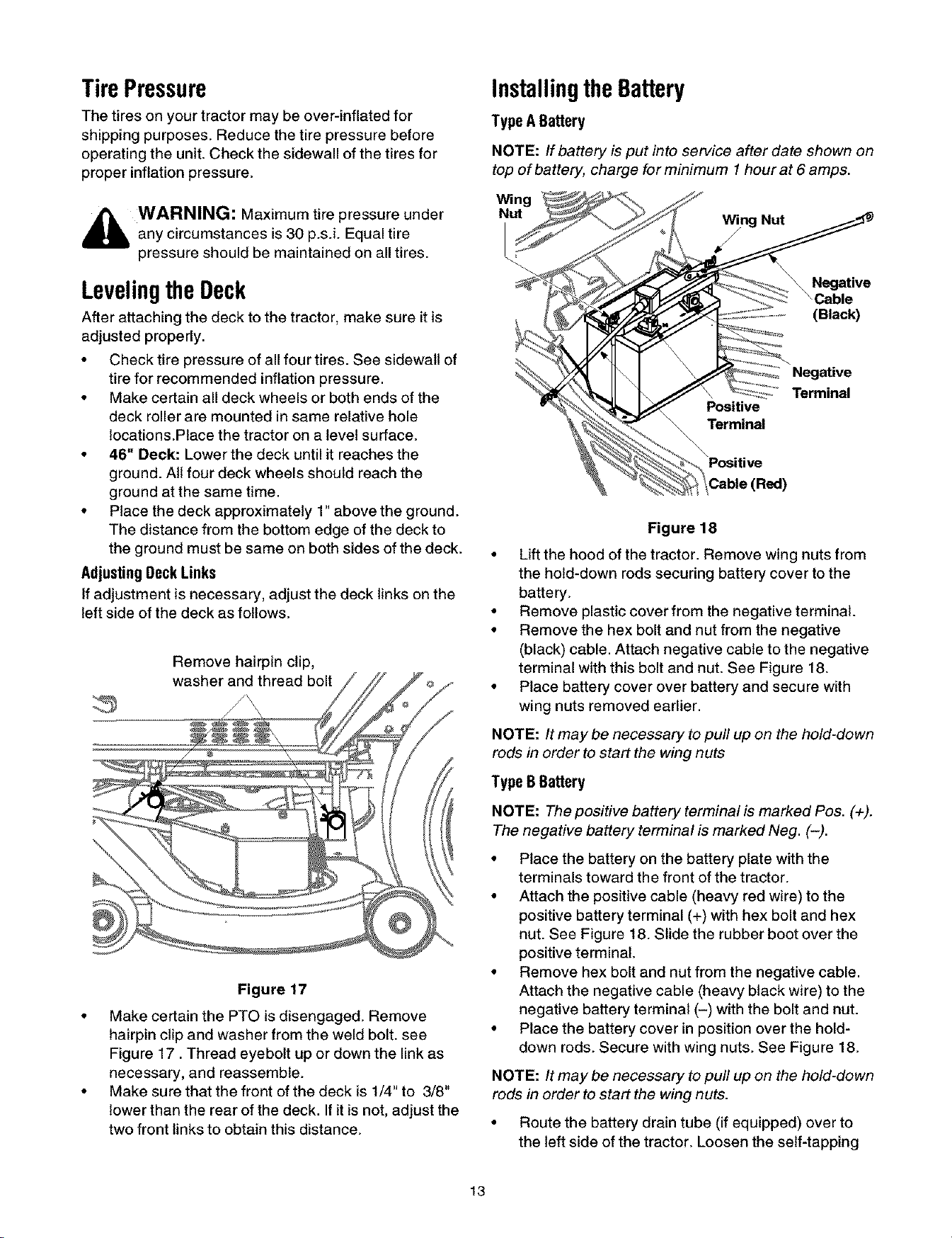
InstallingtheBattery
TypeABattery
NOTE: If battery is put into service after date shown on
top of battery, charge for minimum I hour at 6 amps.
Wing
Nut Wing Nut
(Black)
Negative
Terminal
Positive
Terminal
Positive
Figure 18
• Lift the hood of the tractor. Remove wing nuts from
the hold-down rods securing battery cover to the
battery.
• Remove plastic cover from the negative terminal.
• Remove the hex bolt and nut from the negative
(black) cable. Attach negative cable to the negative
terminal with this bolt and nut. See Figure 18.
• Place battery cover over battery and secure with
wing nuts removed earlier.
NOTE: It may be necessary to pull up on the hold-down
rods in order to start the wing nuts
TypeBBattery
NOTE: The positive battery terminal is marked Pos. (+).
The negative battery terminal is marked Neg. (-).
• Place the battery on the battery plate with the
terminals toward the front of the tractor.
• Attach the positive cable (heavy red wire) to the
positive battery terminal (+) with hex bolt and hex
nut. See Figure 18. Slide the rubber boot over the
positive terminal.
• Remove hex bolt and nut from the negative cable.
Attach the negative cable (heavy black wire) to the
negative battery terminal (-) with the bolt and nut.
• Place the battery cover in position over the hold-
down rods. Secure with wing nuts. See Figure 18.
NOTE: It may be necessary to pull up on the hold-down
rods in order to start the wing nuts.
• Route the battery drain tube (if equipped) over to
the left side of the tractor. Loosen the self-tapping
13
Loading ...
Loading ...
Loading ...