Loading ...
Loading ...
Loading ...
PAGE 8
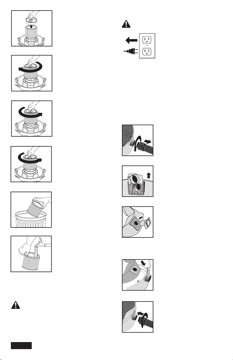
WARNING!
ALWAYS DISCONNECT THE
PLUG FROM THE WALL OUTLET
BEFORE REMOVING THE TANK
COVER.
WARNING!
FIGURE 26
FIGURE 27
FIGURE 28
FIGURE 23
FIGURE 24
FIGURE 25
FIGURE 29
FIGURE 30
FIGURE 20
FIGURE 21
FIGURE 22
40. Place filter retainer into the
top of the cartridge filter.
FIGURE 20.
41. Hold the tank cover with
one hand, turn the handle on
the filter retainer clockwise to
tighten, locking the filter into
place. FIGURE 21.
42. To remove the filter for
cleaning, again hold the
tank cover and turn the filter
retainer counter-clockwise to
loosen and remove.
FIGURE 22.
43. Slide the cartridge filter off
the lid cage. FIGURE 23.
44. To clean cartridge filter
shake or brush off excess dirt.
FIGURE 24.
45. Or rinse (from the inside of
the filter) with water.
FIGURE 25. Dry completely
(approximately 24 hours).
46. Check the filter for tears or small holes. If none are
found, reinstall the filter. To prevent damage to your
vacuum, do not use a filter with a hole or a tear.
KEEP FILTERS CLEAN. EFFICIENCY OF THE VACUUM
IS LARGELY DEPENDENT ON THE FILTER. A CLOGGED
FILTER CAN CAUSE OVERHEATING AND POSSIBLY
DAMAGE THE CLEANER. CHECK THE FILTER
PERIODICALLY AND REPLACE AS REQUIRED.
INSTALLING THE DISPOSABLE FILTER BAG:
47. Use the disposable filter bag in conjunction with the
cartridge filter for easy disposal of the debris. The bag
is not required for normal dry pick up. When picking up
fine dust or powders a high efficiency filter bag (not
standard with all models) must be used.
NOTE: Use for dry pick up only.
48. With cord disconnected from the receptacle, pull
latches in an outward motion and remove the tank
cover.
49. Unscrew hose locking-nut and
remove hose from inlet.
FIGURE 26.
50. Remove the inlet defector
from the deflector guide. NOTE:
Hose must be removed before the
inlet deflector can be taken out.
FIGURE 27.
51. Position the inlet deflector with
the opening facing the left or the
right side of the filter bag. Slide the
filter bag collar over the inlet deflec-
tor, matching the notches of the bag
collar to the tabs on the inlet
deflector. Bag will only fit properly
one way. FIGURE 28.
52. Slide the inlet deflector with the
filter bag attached into the deflector
guide. FIGURE 29.
53. Reinsert hose into inlet and
tighten the locking-nut.
FIGURE 30.
Loading ...
Loading ...
Loading ...