
5-IN-1 WIRELESS
WEATHER STATION
WITH WI-FI
USER GUIDE
LOWSC510WB

2
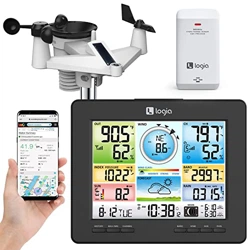
Thank you for purchasing the Logia
™
5-in-1 Wireless Weather Station with WI-FI. This User
Guide is intended to provide you with guidelines to ensure that operation of this product is safe and
does not pose risk to the user. Any use that does not conform to the guidelines described in this User
Guide may void the limited warranty.
Please read all directions before using the product and retain this guide for reference. This product is
intended for household use only. It is not intended for commercial use.
This product is covered by a limited one-year warranty. Coverage is subject to limits and exclusions.
See warranty for details.
SAFETY PRECAUTIONS
PRODUCT FEATURES
PACKAGE CONTENTS
DISPLAY CONSOLE OVERVIEW
LCD DISPLAY OVERVIEW
WIRELESS WEATHER SENSOR OVERVIEW
WIRELESS WEATHER SENSOR SETUP
DISPLAY CONSOLE SETUP
WI-FI CONNECTION
CREATE WEATHER SERVER ACCOUNT
ACCESSING WEATHER DATA ONLINE
OTHER CONSOLE SETTINGS AND FUNCTIONS
CARE AND MAINTENANCE
SPECIFICATIONS
QUESTIONS?
3
4
5
6
7
8
10
13
15
20
23
24
34
35
39
TABLE OF CONTENTS

3
SAFETY PRECAUTIONS
1. Do not let children use or play with this device. It is not a toy.
2. Do not use any attachments not supplied or recommended by the manufacturer.
3. Do not place the appliance near open ames or heat sources. Fire, electric shock, product damage,
or injury might occur.
4. Do not mix old and new batteries in the display unit.
5. A low battery symbol will appear in the OUT or CH sections of the LCD display when battery
power is low on the console or weather sensor, respectively. Be sure to change the batteries
promptly to ensure the proper operation of the weather station.
6. Do not subject the display unit to excessive force or shock (do not throw the unit!), dust, extreme
high or low temperatures, or humidity/moisture. These can cause the unit to stop functioning as
well as present the risk of shock, re, or other hazards.
7. Do not cover the ventilation holes on the display with newspapers, curtains, or any other items.
8. Never immerse the display in water! If you spill any liquid on the display, dry it immediately with a
soft, lint-free cloth.
9. Do not use abrasive or corrosive materials to clean the display.
10. Do not tamper with the display or the weather vane’s internal components. This invalidates your
limited warranty.
11. Placing this product on certain types of wood may result in unintended damage to the nish,
for which Logia™ will not be responsible. Consult your furniture manufacturer’s instructions for
information on wood care.
12. Do not dispose of old batteries as unsorted municipal waste. Make sure to dispose of them properly
according to your local guidelines.
13. The main display console is only intended for use indoors.
QUESTIONS OR PROBLEMS? CONTACT US!
Email: [email protected] or call: 1-833-815-0568
www.logiaweatherstation.com

4
PRODUCT FEATURES
1. Wireless 5-in-1 weather sensor measures wind speed, wind direction, rainfall, temperature, and
humidity.
2. No calibration needed! The product is fully pre-calibrated and mostly assembled; all you need to do
is install it and sync with the included display console.
3. Provides precise weather and environmental information directly from your own backyard, instead
of relying on a national weather station.
4. Color LCD display with dimmable backlight.
5. Can alert you to excessively high/low indoor or outdoor temperatures or humidity, high wind speeds,
extreme drops in barometric pressure, high heat indexes, low wind chills, and high/low dew points.
6. Syncs with installed WI-FI and online weather servers (Weather Undergound and Weathercloud) to
help you store and track weather data in your area, plus view live weather statistics and historical
weather trends.

5
PACKAGE CONTENTS
MAX/MINHISTORYCHANNEL
1. Wireless Weather Sensor (1)
2. Mounting Pole (1)
Plastic Exterior
3. Mounting Clamp (1)
4. Mounting Base (1)
5. Large Mounting Screws (4)
6. Large Hexagonal Nuts (4)
7. Large Washers (4)
8. Small Screws (2)
9. Small Hexagonal Nuts (2)
10. Rubber Pads for Mounting
Clamp
11. Display Console with
Kickstand (1)
12. Display Console Battery (1)
13. Display Console Power Cable (1)
14. User Guide
1
2
5
7
8
6
9
4
3
10
11
12
13
14
6
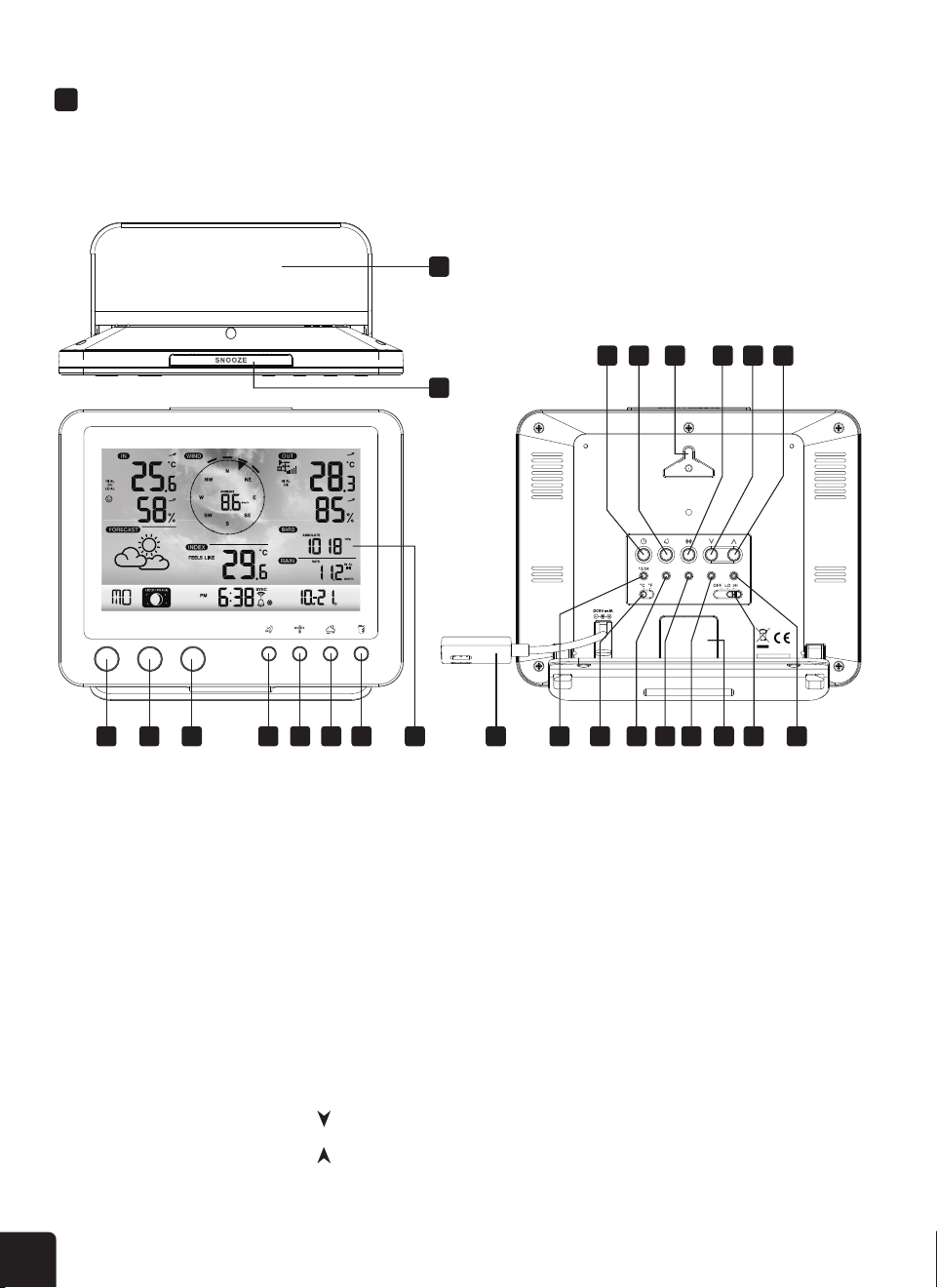
DISPLAY CONSOLE OVERVIEW
MAIN CONSOLE OVERVIEW
1. Kickstand
2. SNOOZE button
3. CHANNEL button
4. HISTORY button
5. MAX/MIN button
6. WIND button
7. INDEX button
8. BARO button
9. RAIN button
10. LCD Display (See overview
on page7
11. CLOCK SET button
12. ALARM button
13. Wall mount notch
14. ALERT button
15. button
16. button
17. Power connection
18. 12/24 button
19. °C/°F button
20. BARO UNIT button
21. SENSOR/WI-FI button
22. REFRESH button
23. Battery compartment
24. OFF/LO/HI button
25. RESET button
MAX/MINHISTORYCHANNEL
WI-FI
SENSOR RESETREFRESH
BARO
UNIT
1
2
3 4 5 6 7 8 9 10 17 18 19 20 21 22 23 24 25
11 12 13 14 15 16
7
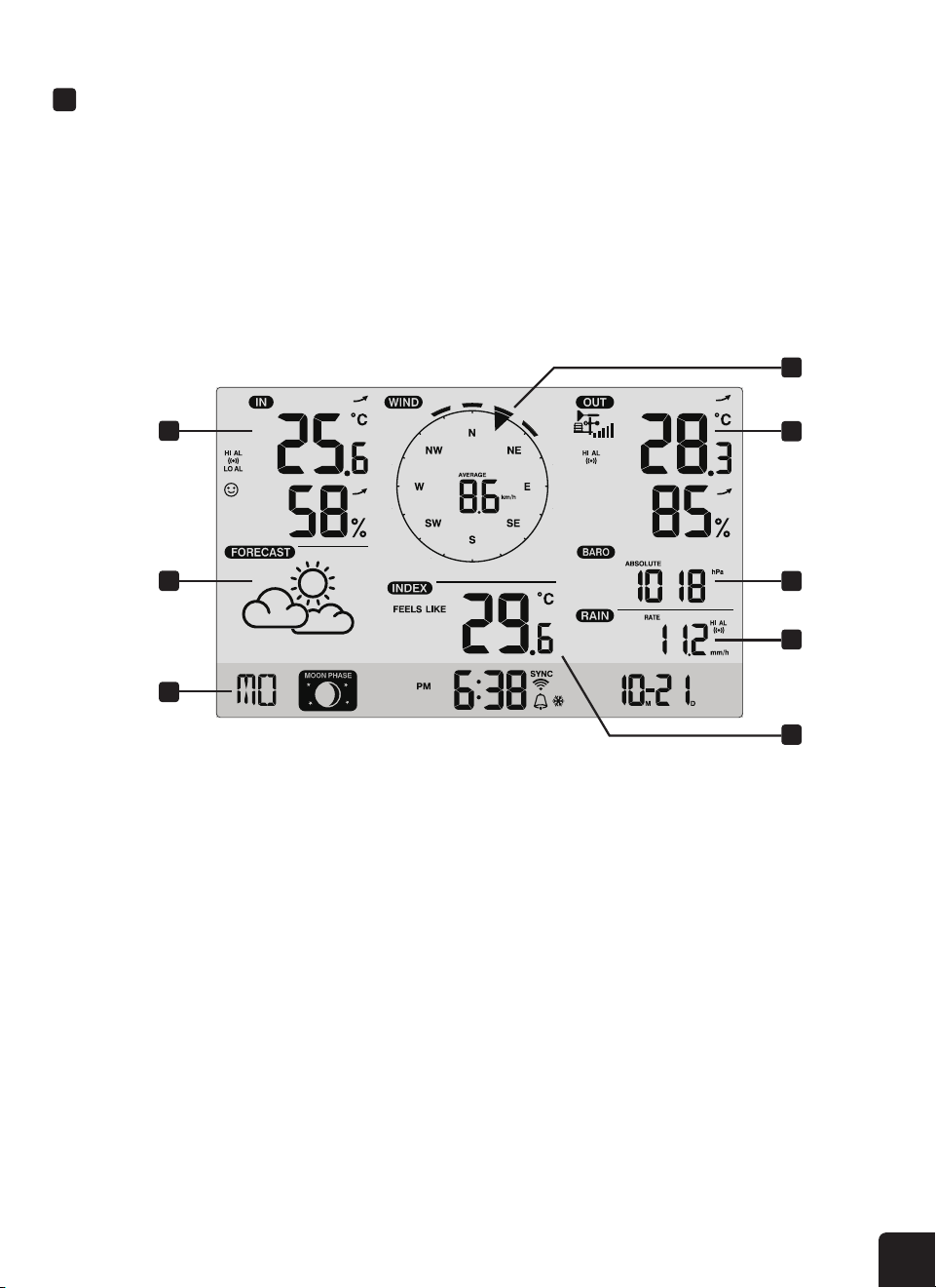
LCD DISPLAY OVERVIEW
1. Temperature & humidity (indoor/CH)
2. Weather forecast
3. Time, date, & moon phase
4. Wind speed & direction
5. Temperature & humidity (outdoor)
6. Barometer
7. Rainfall
8. Weather index
1
4
5
6
7
8
2
3
8
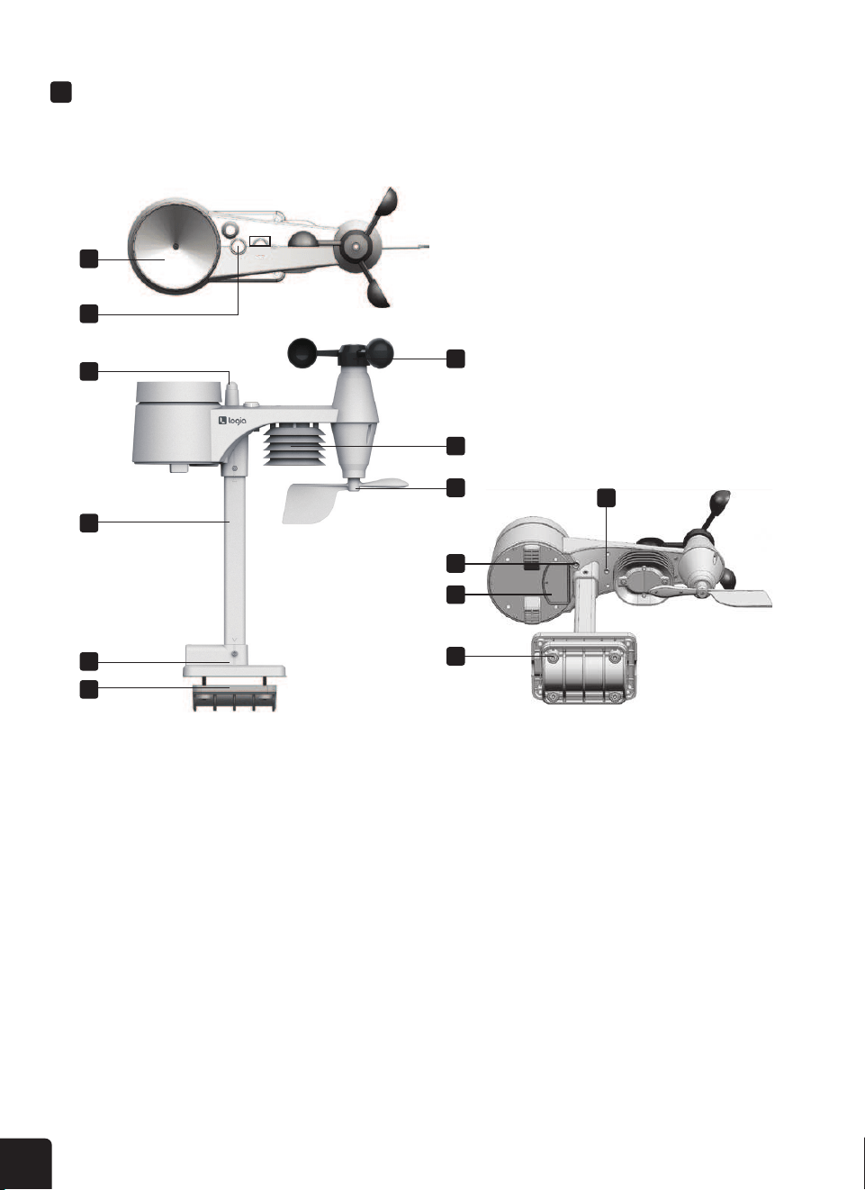
WIRELESS WEATHER SENSOR OVERVIEW
MAIN DEVICE
1. Rain collector
2. Level
3. Antenna
4. Wind cups (anemometer)
5. Mounting pole
6. Sensor casing
7. Wind vane
8. Mounting base
9. Mounting clamp
10. Red LED indicator
11. RESET button
12. Battery compartment
13. Mounting clamp
screws
1
4
2
6
3
7
10
11
12
5
13
8
9
9
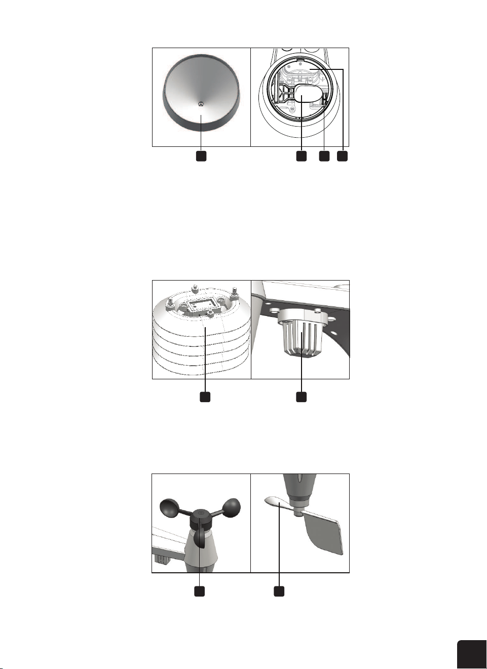
RAIN GAUGE
TEMPERATURE AND HUMIDITY SENSOR
WIND SENSOR
1. Rain collector
2. Tipping bucket
3. Drain holes
4. Rain sensor
1. Sensor shield
2. Temperature and
humidity sensor
1. Wind cups (anemometer)
2. Wind vane
1
1
1
2
2
2
3 4

10
WIRELESS WEATHER SENSOR SETUP
INSTALL BATTERIES
ASSEMBLE STAND AND POLE
1. Unscrew the door to the battery compartment on the underside of the main sensor unit.
2. Insert three (3) new AA alkaline batteries, making sure the polarities match up with the markings
inside the compartment.
1. Insert the top of the pole into the square hole at the bottom of the weather sensor. Ensure that the
arrow indicators are lined up as shown.
3. Replace the battery door, ensuring the watertight O-ring is properly aligned. This maintains the
water-resistant seal.
4. Replace the battery screw, making sure it is tightly fastened down. The red LED should begin
ashing every 12 seconds.

11
2. Insert the nut into the hexagonal hole by the sensor and hold it in place, then insert the screw
through the other side. Use a screwdriver to tighten the screw. Do not insert the screw rst, or the
nut may not line up correctly with the designated hole.
3. Insert the bottom of the pole into the square hole on the plastic stand, making sure the arrows are
lined up as shown.
Please note that there are two di erent ways you can attach the pole to the base, depending on how you
will be mounting it outdoors. If you will be fastening the sensor directly to a railing, use the option that
positions the stand perpendicular to the sensor pole. If you will be fastening it to a pole, use the slot
that positions the base parallel to the sensor pole.
2. The red LED will begin ashing every 12 seconds.
hole

12
MOUNT THE SENSOR OUTDOORS
If securing to a railing, make sure the railing is made of suitable material, and screw directly through
the openings in the base stand into the railing until secure.
1. The wireless weather sensor should be mounted in an open area with no obstructions above and/
or around it, so that it can accurately measure the rain and wind.
2. The wind vane should be pointed due North (refer to the arrow on top of the unit) in order to be
properly oriented and receive accurate wind readings.
3. The mounting stand and included clamps should be secured to a post or pole, with a minimum of
4.9 ft. (1.5 m) ground clearance.
4. If securing to a pole, make sure you add the rubber pads to the clamp before fastening it with the
included screws. The pole should be between 1″-1.3″ in diameter.
4. Insert the nut into the hexagonal hole on the side of the stand and hold it in place, then insert the
screw through the other side. Use a screwdriver to tighten the screw.
Install the wireless 5-IN-1 sensor in an
open location with no obstructions above
and around the sensor for accurate
rain and wind measurement. Install
the sensor with the smaller end facing
the North to properly orient the wind
direction vane.
Secure the mounting stand and bracket
(included) to a post or pole, and allow
minimum 1.5m off the ground.
1.5 meter off
the ground
Add rubber
pads before
mount on
the pole
Point to
NORTH
Your console can pairing up with the wireless 5-IN-1 outdoor weather sensor and up to 7
optional wireless sensors. (Not included)
Remove the battery door of the console.
Insert a new button cell battery.
Replace the battery door.
The backup battery can backup: Time & Date, Max/Min & Past 24 hours weather records, Alert
setting values, offset value of weather data and Sensor(s) channel history.
The built-in memory can backup: Router setting and Weather server setting
Plug the power adaptor to power up the console.
Once the console power up, all the segments of the LCD will be shown.
The console will automatically start AP mode.
If no display appears on the LCD after you plug the adaptor, press key by using a
pointed object.
key in normal mode to adjust LCD viewing angle to t table stand or wall
mount situation.
A
MOUNTING ON POLE
(POLE DIAMETER 1”-1.3”)
(25-33MM)
Point to NORTH
Add rubber
pads before
mount on
the pole
1.5 meter off the
ground

13
INSTALLING THE BACKUP BATTERY
POWERING THE DISPLAY CONSOLE
Your display console can pair with the wireless weather sensor as well as up to seven (7) optional
wireless hygro-thermo outdoor sensors (not included).
5. The mounting location should be within 492 ft. (150 m) of the location where you will be keeping
the display console with few obstructions and relatively clear sightlines. If there are multiple walls/
levels/buildings in between the sensor and the display console, the functionality could be
compromised and you will need less space between the two.
6. Use the built-in level to make sure the sensor is parallel with the ground.
1. Detach the table stand.
2. Unscrew the console battery door screw.
3. Remove the battery door.
4. Insert a new button cell battery.
5. Replace the battery door and tighten the screw.
NOTE: The backup battery can assist with backing up the time & date, MAX/MIN data, weather
records from the past 24 hours, alert settings, the oset value of weather data, and the sensor(s)
channel history. The built-in memory will backup router and weather server settings.
1. Connect the power cable to a wall outlet or power source and to the display console power
connection port.
2. The display console should power on, and all the segments of the LCD display screen should be shown.
3. The display console will automatically start AP mode.
DISPLAY CONSOLE SETUP
Screw
CR2032
B
MOUNTING ON A RAILING

14
PAIRING THE WIRELESS WEATHER SENSOR WITH THE DISPLAY CONSOLE
SET THE LCD DISPLAY VIEWING ANGLE
CHANGING BATTERIES AND MANUAL PAIRING
Whenever you change the batteries in the sensor, you will need to manually repair it with the display
console. Follow these instructions to manually pair your console with the sensor.
1. Once your display console powers on, it should automatically search for and connect to the
wireless weather sensor. If the console does not connect within the rst 15 minutes, refer to the
following section, Changing Batteries and Manual Pairing, for instructions on manual pairing.
2. You will see the icon of an antenna blinking in the temperature and humidity (outdoor) section of
the display.
3. Once the pairing process completes, the antenna icon will appear solid (not blinking), and the
readings for outdoor temperature and humidity, wind speed, wind direction, and rainfall will
appear in their designated sections of the LCD display.
If you have the display console wall-mounted or on a table stand, the viewing angle may need
adjustment. Press or buttons while the display is in normal operating mode to adjust the
viewing angle.
NOTE: If nothing appears on the LCD display screen after you plug in the power adaptor, use a pin or
similar small object to press the RESET button.
1. Change the batteries in the wireless weather sensor.
2. Press the SENSOR/WI-FI button at the back of the console.
3. Press the RESET key on the underside of the wireless weather sensor. Make sure after pressing
the RESET key that the red LED indicator is ashing every 12 seconds.
WI-FI
SENSOR
RESET
REFRESHBARO
UNIT
3
1 2

15
PAIRING ADDITIONAL WIRELESS SENSORS WITH THE DISPLAY CONSOLE
NOTE: Any time you press the RESET key underneath the wireless weather sensor, it generates a
new ID code for pairing with the console, and you will need to press the SENSOR/WI-FI button on the
console for the two devices to pair again.
The display console should automatically search and pair with any additional wireless hygro-thermo
outdoor sensors you install. You can also press the SENSOR/WI-FI button to search manually for the
sensor while on the channel where it should display. Once your sensor has paired, the sensor signal
strength indicator and weather information will appear in the temperature and humidity (outdoor)
section when you are on the channel associated with that sensor.
WI-FI CONNECTION
SET UP WI-FI CONNECTION
When you rst power up the console, or press and hold the SENSOR/WI-FI button for six (6) seconds,
the console LCD display will show the letters “AP” and an
icon to signify that it has entered
Access Point (AP) mode. At this time it will be ready for the WI-FI settings to be adjusted.
Use your smartphone, tablet, or computer to connect to the console via WI-FI by following these steps:
1. On PC, open your WI-FI network settings. On Android
™
or iOS devices, go to settings menu
and then select Connections/WI-FI to open the network settings.
2. Locate the display console’s SSID from the list. It should appear as PWS-XXXXXX (where all
the X’s are integers) in the list. Tap on the SSID to connect. This step will take several seconds.
The console will automatically search and pair up your wireless sensor(s)
paired up, the sensor signal strength indicator and weather information will appear on your
This unit is designed to automatically synchronize its calendar and clock when connected to
, the unit will automatically synchronize the time instantly and 12:00am per day
The time sync function only work with the PC software "W
ime sync up is according to your current PC time, so please ensure your PC time is
Once the PC time sync up the
icon will appear in the
ou can also enable or disable auto time sync function by press and hold
Jot down your ID and key for the further setup step.
When you rst power up the console, or press and hold the
seconds in normal mode, the console LCD will show "AP" and "
entered AP (access point) mode, and is ready for WI-FI settings.
Use the smart phone, tablet, or computer to connect to the console through WI-FI.
In PC choose WiFi network settings or In Android / iOS choose setting →
console’s SSID: in the list and it will need several second to connect.
PC WI-FI network interface Android WI-FI network interface
Once connected, enter the following IP address into your internet browser’s address bar, to
access the console’s web interface:
http://192.168.1.1
Some browsers will treat as a search, so make sure you include header.
Recommended browsers, such as the latest version of Chrome, Safari, Edge, Firefox or
Opera.
Jot down your ID and key for the further setup step.
When you rst power up the console, or press and hold the
seconds in normal mode, the console LCD will show "AP" and "
entered AP (access point) mode, and is ready for WI-FI settings.
Use the smart phone, tablet, or computer to connect to the console through WI-FI.
In PC choose WiFi network settings or In Android / iOS choose setting →
console’s SSID: in the list and it will need several second to connect.
PWS-XXXXXX
PWS-XXXXXX
PC WI-FI network interface Android WI-FI network interface
Once connected, enter the following IP address into your internet browser’s address bar, to
access the console’s web interface:
http://192.168.1.1
Some browsers will treat as a search, so make sure you include header.
Recommended browsers, such as the latest version of Chrome, Safari, Edge, Firefox or
Opera.

16
3. Once you are connected to the display console, open up your internet or mobile web browser,
and enter the following address into the address bar: http://192.168.1.1 (make sure to include
the http:// or else the web browser may interpret the address as a search query). We
recommend using the latest version of reputable web browsers.
SET UP WEATHER SERVER CONNECTION
Once you are connected via WI-FI to the display console and have opened the settings page at
http://192.168.1.1, enter the following information into the web interface setup page. If you have
chosen not to use Weather Underground or Weathercloud’s servers, leave the check boxes unchecked.
Function firmware version: 1.00
WiFi firmware version: 1.00
nist.time.gov
Server URL:
Time server setup
WIFI Router setup
SETUP ADVANCED
Wunderground
Station ID:
WDw124
******
******
******
IPACIR23Wc
Weather server setup
Station key:
Router:
Add Router
Search
Security type:
Router Password:
WAP2
ROUTER_A
Apply
Language: English
Weathercloud
Station ID:
Station key:
Mac address 00:0E:C6:00:07:10
Press to search router
Select the WI-FI router (SSID) you will connect to
Manually enter the SSID if not on the list
Select router’s security type (usually WAP2)
Enter new Station ID and Station key assigned
by Wunderground (Weather Underground)
Select time server
Press to complete the setting
SETUP page
Router’s password (leave blank if unsecured)
Press to allow add
router manually
Password record remark
(If you entered password)
Current ID and
key recorded (if any)
Current ID and key
recorded (if any)
Enter new Station ID and Station key
assigned by Weathercloud
Press “SETUP” icon
to SETUP page
If you don’t have Station ID and Station Keys available for the upload you need to rst create an account at the
respective weather servers of Weather Underground (WU) and WeatherCloud (WC), followed by registering
the product to obtain the ID and keys. For details, please refer to session on “CREATE WEATHER SERVER
ACCOUNT”.

17
NOTES: When the WI-FI setup is complete, your computer or mobile device will return to the default
WI-FI connection. If it does not, simply open your device’s wireless network settings and manually
reconnect.
While in AP mode, you can press and hold the SENSOR/WI-FI button for six (6) seconds to exit AP
mode. The display console will simply restore the previous AP settings.
WI-FI CONNECTION STATUS
TIME SERVER CONNECTION STATUS
ADVANCED SETTINGS VIA WEB INTERFACE
The following icons on the LCD display screen show the WI-FI status:
Once the display console has connected to the internet, it will attempt to connect to the internet time
server to obtain the UTC time. Once the connection is successful and the time has been updated, the
“SYNC” icon will appear above the WI-FI icon on the LCD.
Once you are connected via WI-FI to the display console and have opened the settings page at
http://192.168.1.1, clicking on the tab that says ADVANCED will open the following page. This page
will allow you to set and view specic calibration data of your display console, and also update the
rmware if you are on PC.
To display the correct time for your specic time zone, you’ll need to change the time zone in the
CLOCK setting mode from 00 (default) to your specic time zone (e.g. -5 for EST). If you don’t know
your time zone, you can look it up online.
1. In normal operating mode, press and hold the CLOCK SET button for two (2) seconds to enter
the clock setting menu.
2. Press the or buttons to adjust the time zone, and then press and hold the CLOCK SET
button for two (2) seconds to conrm and exit the menu. Please refer to the Setting the Time
section of the manual on page 24 for details of other available clock settings.
The time will automatically sync with the internet time server at 12:00AM and 12:00PM each day. If you
would like to force it to sync sooner than that, press the REFRESH button on the console to update the
time in the next minute.
Select the Wi-fi router (SSID) you will connect to
Manually enter the SSID if not on the list
Select router’s security type (usually WAP2)
Check to confirm upload to Weather Underground
Enter new Station ID and Station key assigned
by Wunderground (Weather Underground)
Check to confirm upload to Weathercloud
Select time server
Press to complete the setting
Router’s password (leave blank if unsecured)
Press to allow add
router manually
Password record remark
(If you entered password)
Current ID and
key recorded (if any)
Current ID and key
recorded (if any)
Enter new Station ID and Station key
assigned by Weathercloud
Solid: the display console is
connected to your wireless router
Flashing: the display console is
attempting to connect to your wireless router
Flashing: the display console is
currently in AP (access point) mode
Press “SETUP” icon
to SETUP page
Below is the WI-FI icon status on the console LCD:
Flashing: Console is trying to
connect to WI-FI router
Select the Wi-fi router (SSID) you will connect to
Manually enter the SSID if not on the list
Select router’s security type (usually WAP2)
Check to confirm upload to Weather Underground
Enter new Station ID and Station key assigned
by Wunderground (Weather Underground)
Check to confirm upload to Weathercloud
Select time server
Press to complete the setting
Router’s password (leave blank if unsecured)
Press to allow add
router manually
Password record remark
(If you entered password)
Current ID and
key recorded (if any)
Current ID and key
recorded (if any)
Enter new Station ID and Station key
assigned by Weathercloud
Solid: the display console is
connected to your wireless router
Flashing: the display console is
attempting to connect to your wireless router
Flashing: the display console is
currently in AP (access point) mode
Press “SETUP” icon
to SETUP page
Flashing: Console is trying to
connect to WI-FI router
updated, the “ ” icon will appear on the LCD.

18
CALIBRATION
1. You may enter or change the o set and gain values for di erent measurement parameters,
while viewing the current o set and gain values next to the corresponding boxes.
2. Once you have completed your calibrations, press the APPLY button on the SETUP tab.
3. The current o set value will update to show the value that you entered (instead of the default
value). If you want to change the value, you can enter a new value in the box beside the
number (as in step 1). To update the value, again, press APPLY in the SETUP tab.
NOTE:
We do not recommend calibration of most values with the exception of Relative Pressure, which must
be correctly calibrated to re ect your distance above sea level to account for altitude e ects.
-800 ~ 800hpa / -23.62 ~ 23.62inHg / -601.5 ~ 601.5mmHg
Setting Range:
SETUP ADVANCED
Language: English
Temperature
o
C
Outdoor
Indoor
CH 1
CH 2
CH 3
CH 4
CH 5
CH 6
CH 7
Humidity %
Relative Pressure Offset:
Absolute Pressure Offset:
hpa
Range: -20 ~ 20
(Default: 0)
Current offset: 10Current offset: -9
Current offset: -5Current offset: 2
Current offset: -2Current offset: 3
Current offset: -2Current offset: 1.2
Current offset: -5Current offset: -0.2
Current offset: -3Current offset: -20.1
Current offset: -10Current offset: 11.5
Current offset: -3
Current offset: -3
(Default: 0)
Current offset: 10
(Default: 0)
Current offset: 0.2
Current offset: -5Current offset: 1
Pressure
Range: -20.0 ~ 20.0
o
C
-36.0 ~ 36.0
o
F (Default: 0.0)
**UV gain:
Range: 0.01 ~ 10(Default: 1.00)
Current gain: 1.1
** Depends on outdoor sensor type
Wind speed gain:
**Wind direction:
Rain gain:
Range: 0.5 ~ 1.5(Default: 1.00)
Range: -10 ~ 10(Default: 0
o
)
Range: 0.5 ~ 1.5(Default: 1.00)
Current gain: 0.85
Current offset: 2
o
Current gain: 0.75
Function firmware version: 1.00
WiFi firmware version: 1.00
Temperature calibration section
Pressure calibration section
Rain calibration section
Wind calibration section
Select setting unit
Advanced page
CALIBRATION
Press ‘ADVANCED’ icon to view
the advanced settings page
Humidity calibration section
Select setting unit

19
UPDATING THE FIRMWARE
This display console supports OTA (over the air) Function Firmware and WI-FI System Firmware
updates via any web browser (not mobile browser) on a PC that is connected to WI-FI. The update
function for both types of updates can be found at the bottom of the Advanced Tab on the wireless
settings interface (see Advanced Settings via Web Interface on page 20.
Follow the steps below to update your device’s Function or WI-FI System Firmware
1. Download the latest version of the rmware (function or WI-FI) and save it to your PC.
Remember where you saved the le.
2. Press and hold the SENSOR/WI-FI button for six (6) seconds to put the display console into AP
mode, then connect the PC to the console (refer to steps in Set Up WI-FI Connection on page 18.
3. Click the button that says Browse next to the appropriate type of update that you downloaded
and navigate to the location where you saved the le.
4. Click the corresponding Upload button to transfer the update le to the console.
5. The le will install automatically once it is uploaded. You can view update progress on the
display console in the wind direction section (the number displayed will correspond to the
percentage completed, so 50 = 50% and so on).
You can also use the Apple ipad's "WunderStation" app to login your own weather station to
view the live data.
underStatio
To view your weather station live data in a web browser (PC or mobile version), please visit
https://weathercloud.net and sign in your own account.
icon inside the pull down menu of your station.
", " ", " " icon to view the live data of your weather
The console supports OTA rmware update capability. Its rmware may be updated over the
air anytime (whenever necessary) through any web-browser on a PC with WI-FI connectivity.
Update function, however, is not available through mobile/smart devices.
Two types of rmware updates are available, namely Function Firmware and System WI-FI
Firmware, and are located at the bottom of ADVANCED page.
Current Function
firmware version
Current WI-FI
firmware version
Current Function
rmware version
Current WI-FI
rmware version
Download the latest version rmware (function or WI-FI) to your PC.
Set the Console into AP (access point) mode then connect the PC to the console (ref to
"SETUP WI-FI CONNECTION" section in previous page).
To update the Function rmware, click the
Browse
in Function rmware section and
browse to the location of the le you download in step 1. To update the WI-FI rmware, click
Browse
in WI-FI rmware section.
Click the corresponding
Upload
transfer the rmware le to console (indicated by
a transfer completion %).
Upload
30% ...
BrowseC:\download\PWS_SYS.bin
Upload
Browse
Function firmware version: 1.00
WiFi firmware version: 1.00
3
4
Once the console received the rmware le, it
executes the update automatically as indicated
by the update progress on display (i.e. 100 is
completion).
The console will restart once the update completed.
Function and WI-FI rmware cannot be updated at the same time, you need to update one by
Please keep connecting the power during the rmware update process.
Please make sure your PC's WI-FI connection is stable.
When the update process start, do not operate the PC and console.
During rmware update the console will stop upload data. It will reconnect to your WI-FI router
and upload the data again once the update success. If the console cannot connect to your
router, please end the SETUP page to setup again.
After the rmware updates, user might need to input the Weather Underground ID and
password again.
This console is designed to obtain the local time by synchronize with the assigned internet time
server. If you want to use it ofine, you can set the time and date manually. During the rst time
startup, press and hold the key for 6 seconds and let the console back to
normal mode.
In normal mode, press and hold key for 2 seconds to enter setting.
The setting sequence: Time Zone → → → → 12/24 hour format →
→ → → M-D/D-M format → Time sync ON/OFF → weekday Language.
key to change the value. Press and hold the key for quick-adjust.
key to save and exit the setting mode, or the unit will automatically
exit the setting mode 60 seconds later without pressing any key.
In normal mode, press key to switch between year and date display.
During the setting, you can press and hold key for 2 seconds to back to normal
model.
Download the latest version rmware (function or WI-FI) to your PC.
Set the Console into AP (access point) mode then connect the PC to the console (ref to
"SETUP WI-FI CONNECTION" section in previous page).
To update the Function rmware, click the
Browse
in Function rmware section and
browse to the location of the le you download in step 1. To update the WI-FI rmware, click
Browse
in WI-FI rmware section.
Click the corresponding
Upload
transfer the rmware le to console (indicated by
a transfer completion %).
Upload
30% ...
BrowseC:\download\PWS_SYS.bin
Upload
Browse
Function firmware version: 1.00
WiFi firmware version: 1.00
Once the console received the rmware le, it
executes the update automatically as indicated
by the update progress on display (i.e. 100 is
completion).
The console will restart once the update completed.
Function and WI-FI rmware cannot be updated at the same time, you need to update one by
Please keep connecting the power during the rmware update process.
Please make sure your PC's WI-FI connection is stable.
When the update process start, do not operate the PC and console.
During rmware update the console will stop upload data. It will reconnect to your WI-FI router
and upload the data again once the update success. If the console cannot connect to your
router, please end the SETUP page to setup again.
After the rmware updates, user might need to input the Weather Underground ID and
password again.
This console is designed to obtain the local time by synchronize with the assigned internet time
server. If you want to use it ofine, you can set the time and date manually. During the rst time
startup, press and hold the key for 6 seconds and let the console back to
normal mode.
In normal mode, press and hold key for 2 seconds to enter setting.
The setting sequence: Time Zone → → → → 12/24 hour format →
→ → → M-D/D-M format → Time sync ON/OFF → weekday Language.
key to change the value. Press and hold the key for quick-adjust.
key to save and exit the setting mode, or the unit will automatically
exit the setting mode 60 seconds later without pressing any key.
In normal mode, press key to switch between year and date display.
During the setting, you can press and hold key for 2 seconds to back to normal
model.

20
6. The console will restart once the update completes.
NOTES:
• You cannot update the Function Firmware and WI-FI Firmware at the same time. Updates must be
installed one by one.
• Make sure the power cable remains connected during the update process.
• Make sure your PC’s wireless connection is stable.
• Once the update process starts, do not try to do anything else on your PC or on the display console.
• During the rmware update process, the console will stop uploading data temporarily. It will
reconnect to your router and resume uploading data once the update is complete. If the console
cannot connect to your router, you may need to set up the WI-FI connection again, following the
steps on page 18.
• Once your rmware update completes, you may need to input your Weather Underground ID and
password again on the SETUP tab of the wireless interface.
CREATE WEATHER UNDERGROUND ACCOUNT
1. Visit the Weather Underground website at https://www.wunderground.com and click the link that
says “JOIN”. Follow the instructions to create an account.
NOTE: Please use a valid email address to register your account.
2. Once you have created your account and completed the email validation process, return to the
Weather Underground website. Click the dropdown link at the top of the site that says MORE, and
then select Add Weather Station from the dropdown menu.
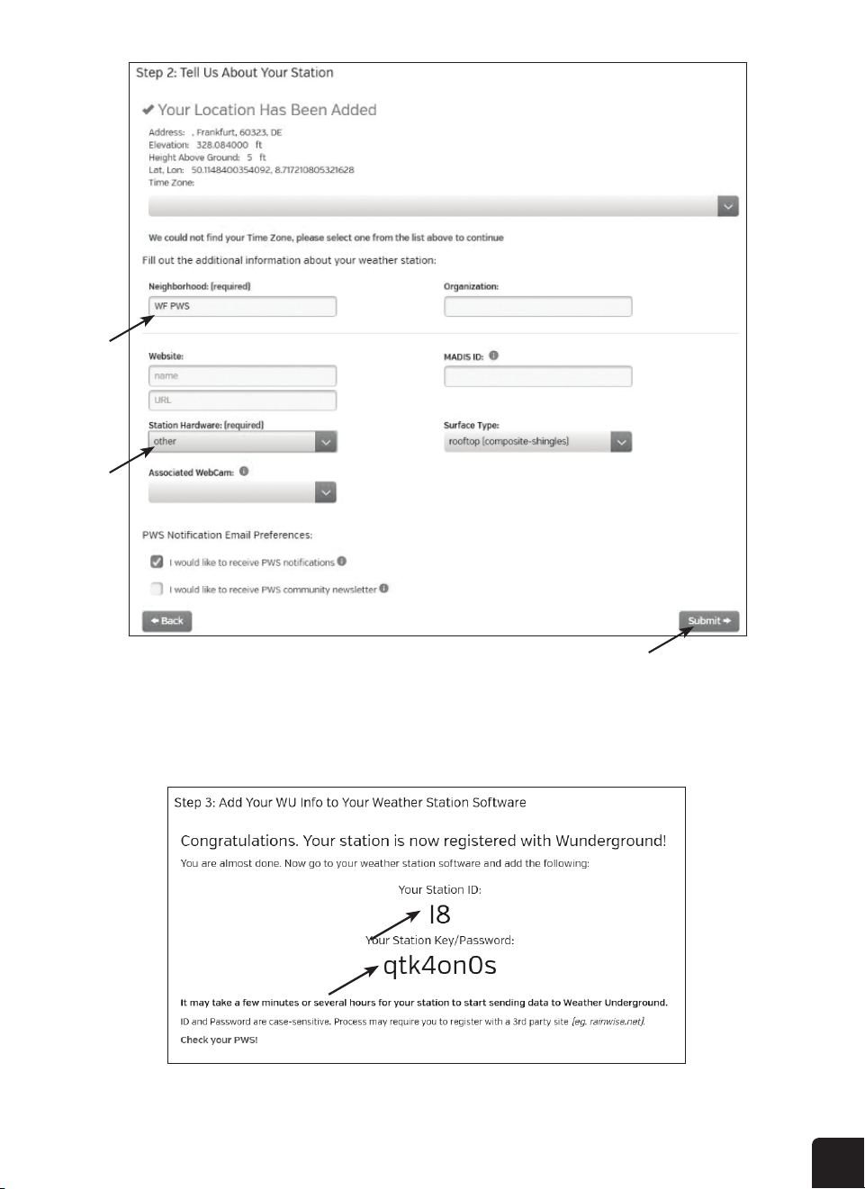
3. Follow the instructions on screen to enter your weather station information. Step 2 will ask you to
enter a name for your weather station (get creative if you want, but don’t forget the name you
gave it!) and choose your station hardware (choose “other”). Once you complete this section, click
Submit to generate your unique Station ID and key.
Your display console can upload weather data to Weather Underground and/or Weathercloud via your
WI-FI router.
NOTE: Logia
™
does not own Weather Underground or Weathercloud, and these instructions are liable
to change without notice due to changes in either website.
CREATE WEATHER SERVER ACCOUNT
and click “Add Weather Station”.
21
4. Write down or screenshot your Station ID and Station Key/Password for reference and to complete
the setup process.

22
CREATE WEATHERCLOUD ACCOUNT
1. Visit the Weathercloud website at https://www.weathercloud.net and enter your information in
the box that says Join Us Today. Follow the instructions to create an account.
NOTE: Please use a valid email address to register your account.
2. Once your account is created, sign into it, and then click +New to add a new device.
3. Enter all the requested information into the Create New Device page. When presented with the
Model selection box, choose LOWSC510WB Series under the Logia section. When presented
with the Link Type selection box, choose Pro Weather Link. Once you have completed this
section, click Create.
enter your information in " " section, then follow
Use the valid email address to register your account.
Sign in weathercloud and then you will go the "Devices" page, click "+ New" to create new
device.
Enter all the information in page, for the selection box select
the "W100 Series" under "CCL" section. for the Link type* selection box select the "Pro
Weather Link", Once you have completed, click

23
VIEW YOUR WEATHER DATA IN WEATHER UNDERGROUND
ACCESSING WEATHER DATA ONLINE
VIEW YOUR WEATHER DATA IN WEATHERCLOUD
To view your weather station data live via PC or mobile web browser, visit http://www.wunderground.
com, and then enter the Station ID you were provided during account setup in the search box. Your
weather data will show up on the next page. Alternately, you can log in to your Weather Underground
account to view and download the recorded data from your weather station.
1. To view your weather station data live via PC or mobile web browser, visit http://www.
weathercloud.net and sign into the account you created.
2. Click on the tab at the top of the page titled Devices.
3. Click on the Settings menu at the top right of the page, and select the option View.
You can also check Weather Underground web site to learn more about their mobile App for Android
and iOS.
4. Write down or screenshot your Weathercloud ID and Station Key/Password for reference and to
complete the setup process.
Jot down your ID and key for the further setup step.
When you rst power up the console, or press and hold the
seconds in normal mode, the console LCD will show "AP" and "
entered AP (access point) mode, and is ready for WI-FI settings.
Use the smart phone, tablet, or computer to connect to the console through WI-FI.
In PC choose WiFi network settings or In Android / iOS choose setting →
console’s SSID: in the list and it will need several second to connect.
PC WI-FI network interface Android WI-FI network interface
Once connected, enter the following IP address into your internet browser’s address bar, to
access the console’s web interface:
http://192.168.1.1
Some browsers will treat as a search, so make sure you include header.
Recommended browsers, such as the latest version of Chrome, Safari, Edge, Firefox or
Opera.

24
OTHER CONSOLE SETTINGS AND FUNCTIONS
MANUALLY SETTING THE TIME
The display console is designed to synchronize with the internet time server to obtain the local time,
but if you want to use it without connecting to your home wireless network, you can set the time
manually. During initial setup, you will need to press and hold the SENSOR/WI-FI button for six (6)
seconds, then let the display console return to normal mode. This will put it into o ine mode for you
to use it.
1. In normal operating mode while o ine, press and hold the CLOCK SET button for two (2)
seconds to enter the clock setting menu.
2. Press the or buttons to adjust the time zone.
3. Press the CLOCK SET button again to make adjustments to the next setting.
4. Settings will cycle through the following options: Time Zone > DST ON/OFF > Hour > Minute >
12/24-hour Format > Year > Month > Day > M-D/D-M Format > Time Sync ON/OFF > Language.
5. Press the CLOCK SET button one nal time after adjusting all settings options to save and exit,
or the console will automatically save and exit the menu after 60 seconds of idle time.
NOTES:
• In normal operating mode, press the CLOCK SET button once to switch between date and year display.
• While adjusting settings, you can press and hold the CLOCK SET button for two (2) seconds to return
to normal mode.
MOON PHASE
The display console calculates the moon phase according to your time, date, and time zone. The table
below explains the corresponding phases and their icons for both Northern and Southern hemispheres.
Please refer to the section regarding Orienting the Wireless Weather Sensor Due South on page 25
for more information on setting up your Wireless Weather Sensor in the Southern Hemisphere.
4. Click on either Current, Wind, Evolution, or Inside to view your weather station’s data.
You can also use the Apple ipad's "WunderStation" app to login your own weather station to
view the live data.
underStatio
To view your weather station live data in a web browser (PC or mobile version), please visit
https://weathercloud.net and sign in your own account.
icon inside the pull down menu of your station.
", " ", " " icon to view the live data of your weather
station.
The console supports OTA rmware update capability. Its rmware may be updated over the
air anytime (whenever necessary) through any web-browser on a PC with WI-FI connectivity.
Update function, however, is not available through mobile/smart devices.
Two types of rmware updates are available, namely Function Firmware and System WI-FI
Firmware, and are located at the bottom of ADVANCED page.
firmware version
firmware version

25
Northern Hemisphere Icons Southern Hemisphere IconsMoon Phase
New Moon
Waxing Crescent Moon
First Quarter Moon
Waxing Gibbous Moon
Full Moon
Waning Gibbous Moon
Third Quarter Moon
Waning Crescent Moon
Alarm o
POINTING THE WIRELESS WEATHER SENSOR TO SOUTH
The outdoor wireless weather sensor is calibrated to be pointed North for maximum accuracy.
However, for your convenience, if you are a user located in the Southern Hemisphere, you can use the
sensor with the wind vane pointing South.
1. Mount and install the wireless weather sensor with the wind meter end pointed South, instead of
North. (Please refer to the Installation Instructions on page 12 for mounting instructions.)
2. While the display console is in normal operating mode, press and hold the INDEX button for eight
(8) seconds until the N icon appears in the weekday section of the display to indicate the console is
in sensor orientation mode.
3. Use the or buttons to change the orientation to Southern Hemisphere. The N should change
to an S.
4. Press the INDEX button another time to conrm and exit the menu.
NOTES:
• Changing the hemisphere setting will automatically switch the direction of the moon phases on the
display.
• Pointing the wireless weather sensor toward the South will allow maximum sunlight on the solar
panel, especially during the winter season in the Southern Hemisphere.

26
SETTING THE ALARM
ACTIVATING/DEACTIVATING THE ALARM & TEMPERATURE PRE-ALARM
The temperature pre-alarm will alert you 30 minutes prior to your alarm time whenever the outdoor
temperature falls below 26.5°F (-3°C).
1. In normal operating mode, press the ALARM button to display the set alarm time for ve (5) seconds.
2. When the alarm time is being shown on the LCD display, press the ALARM button again to cycle
through the alarm functions as shown below. The corresponding icons will appear on the LCD display.
If you’d like to use your display console as an alarm clock, follow these instructions to set the alarm
time:
1. In normal operating mode, press and hold the ALARM button for two (2) seconds until the alarm
hour starts ashing. This indicates that you have entered the alarm time setting mode.
2. Use the or buttons to adjust the alarm hour. Press and hold either button to move through
the hours quickly.
3. Press the ALARM button again to conrm the alarm hour and move to adjusting the minutes. The
minute digits should be ashing.
4. Use the or buttons to adjust the alarm minute. Press and hold either button to move
through the minutes quickly.
5. Press the ALARM button to save and exit the menu.
NOTES:
• Once you have an alarm set, the icon will be displayed next to the time on the LCD display.
• The alarm function will be activated automatically once you set a time.
3. When the clock reaches the designated alarm time, the alarm sound will start playing.
4. To stop the alarm:
a. Allow the alarm to continue for two minutes and it will stop itself automatically. It will remain set
for the following day.
b. Press the SNOOZE/BACKLIGHT button on top of the unit to snooze the alarm for ve minutes.
The snooze can be set continuously for 24 hours. We don’t recommend doing that, though. While
the console is in snooze mode, the alarm icon will continue ashing.
c. Press and hold the SNOOZE/BACKLIGHT BELL for two (2) seconds to stop the alarm completely.
It will stay set for the following day.
d. Press the ALARM button to stop the alarm completely. It will remain set for the following day.
Alarm o Alarm on Alarm with ice-alert

27
TEMPERATURE/HUMIDITY & TRENDS
VIEWING OUTDOOR CHANNELS
RECEIVING WIRELESS SENSOR SIGNALS
Press the °C/°F button to switch between Celsius and Fahrenheit temperature measurements. The
arrows show the trend in changes to the temperature/humidity levels.
This console is capable of pairing with the wireless weather sensor and up to 7 additional wireless
thermal-hygro sensors. If you have 2 or more sensors installed, press the CH button to cycle between
dierent wireless channels in normal operating mode, or press and hold the CH button for two (2)
seconds to toggle auto-cycle mode on, which cycles through displaying all connected channels at
4-second intervals. While the console is in auto-cycle mode, you can press the CH button once to
toggle auto-cycle mode o and continue displaying the current channel.
1. While in normal operating mode, press the SENSOR/SYNC button once to start receiving the
current sensor signal on the channel being displayed. (i.e. if you’re on CH 1 and press the SENSOR/
SYNC button, the current wireless sensor signal being received will only display on CH 1.) The
signal icon will start ashing.
2. The signal icon will continue ashing until it successfully receives a signal. If no signal is received
within ve (5) minutes, the icon will disappear.
NOTE:
• If/when the temperature outside falls below -40°F (-40°C), the LCD display will show the word
“Lo” in the temperature section. If the temperature outside rises above 176°F (80°C), the LCD
display will show the word, “HI” in the temperature section.
• If/when the humidity level falls below 1%, the LCD display will show the word “Lo” in the humidity
section. If/when the humidity level rises above 99%, the LCD display will show the word, “HI” in
the humidity section.
Alarm o
Temp/Humidity Trend
Arrow Icon
Rising Steady Falling
Alarm o
No signal Weak signal Good signal

28
3. If the signal for the outdoor channel has been interrupted and does not recover within 15 minutes,
the signal icon will disappear. The temperature and humidity section (outdoor) will display “—” on
the corresponding channel.
4. If the signal still does not recover within 48 hours, the “—” display will become permanent. You will
need to replace the batteries on the associated channel’s sensor and press the SENSOR/SYNC
button to pair up the sensors again.
5. After replacing batteries in the display console or the wireless weather sensor, or if the unit fails to
receive a specied channel, press the SENSOR/SYNC button while the failed channel is being
displayed to manually receive that sensor’s signal again.
1. While in normal operating mode, press and hold the WIND button for two seconds to enter the
wind speed unit setting mode. The unit display will start ashing. Press the or buttons
to cycle through the wind speed units in the following order: m/s > km/h > knots > mph
INDOOR COMFORT INDICATOR KEY
SELECTING WIND DISPLAY MODE
WIND READOUTS
Real time wind
direction indicator
Past wind
directions indicator
of last 5 minutes
Average / gust
wind speed
Wind Direction
Set Wind Speed Units
The indoor comfort indicators display a pictorial representation based on the indoor air temperature
and humidity levels to determine the approximate comfort level.
While in normal operating mode, press the WIND button to switch between the average wind speed
measurement and gust wind speed measurement.
NOTE:
Comfort indicator levels may vary even when the temperature is the same due to variances in relative
humidity levels. No comfort indicator will be displayed if the temperature falls below 32°F (0°C) or
over 140°F (60°C).
Alarm o
Too cold Comfortable Too hot
The console display signal strength for the wireless 5-IN-1 sensor, as per table below:
If the signal has discontinued and does not recover within 15 minutes, the signal icon will
disappear. The temperature and humidity will display “Er” for the corresponding channel.
If the signal does not recover within 48 hours, the “Er” display will become permanent. You
need to replace the batteries and then press key to pair up the sensor
This console is capable to pair with a wireless 5-IN-1 sensor and up to 7 wireless thermal-hygro
sensors. If you have 2 or more sensors, you can press key to switch between
different wireless channels in normal mode, or press and hold key for 2 seconds
to toggle auto-cycle mode to display the connected channels at 4 seconds interval.
During auto-cycle mode, press key to stop auto cycle and display the current
AND DIRECTION SECTION OVERVIEW
Past wind
directions indicator
of last 5 minutes
Real time wind
direction indicator
Average / gust
wind speed
In normal mode, press and hold key for 2 seconds to enter into wind speed unit
mode and the unit will ash. Press key to change the wind speed unit in this
sequence: m/s → km/h → → mph
key again to return to normal mode.
In normal mode, press key to switch between and wind speed.
At the WEATHER INDEX section, you can press key to view the weather index in this
sequence: FEELS LIKE → HEAT INDEX → WIND CHILL → DEWPOINT.
The feels like temperature index determine how the outdoor temperature that people actually

29
2. Press the WIND button again to return to normal display mode.
3. Press the WIND button while in normal operating mode to switch between AVERAGE and GUST
wind speeds.
WEATHER INDEXES
Wind Speed Level Chart
Feels Like
Wind Chill
When reading the Weather Index display, you can press the INDEX button to cycle through dierent
weather indexes in the following order: Feels Like > Heat Index > Wind Chill > Dewpoint.
The Feels Like temperature index determines what temperature it actually feels like outside, taking
into account factors like wind chill and the heat index.
Wind chill is determined by a combination of the wireless weather sensor’s temperature and wind
speed data.
last five minutes
Real-time wind
Average / gust
→ → →
Speed
Level
0.1~11.8 mph
Light
12~30.4 mph
Moderate
31~54.7 mph
Strong
>55 mph
Storm
Heat Index
Dew Point
The heat index is determined by the wireless weather sensor’s temperature and humidity readings
when the temperature outdoors is between 80°F (27°C) and 120°F (50°C).
• The dew point is the temperature below which the water vapor in air at constant barometric
pressure condenses into liquid water at the same rate at which it evaporates. The condensed water
is called dew when it forms on a solid surface.
• The dew point temperature is determined by the temperature and humidity data from the wireless
weather sensor.
flags extended.
Eort needed to walk
Some branches break o trees,
Trees are broken o or
Umbrella use becomes dicult.
≥ 118 km/h
≥ 74 mph
≥ 64 knot
≥ 32.7m/s
Heat Index range Warning Explanation
80°F to 90°F (27°C to 32°C) Caution Possibility of heat exhaustion
91°F to 105°F (33°C to 40°C) Extreme Caution Possibility of heat dehydration
106°F to 129°F (41°C to 54°C) Danger Heat exhaustion likely
≥ 130°F (≥ 55°C) Extreme Danger Strong risk of dehydration / sun stroke

30
NOTE:
• The accuracy of a general pressure-based forecast is about 70% - 75%. Forecasts are not
guaranteed.
• The forecast section reects a general prediction for the next roughly 12 ~ 24 hours. It may not
necessarily reect the current situation.
• The SNOWY weather forecast is not based on the atmospheric pressure, but based on the current
temperature reading from that wireless sensor. When the outdoor temperature is below ~ 26°F
(-3°C), the SNOWY weather indicator will be shown on the LCD display.
The built-in barometer can notice atmospheric pressure changes, and based on the data collected,
can predict the weather conditions in the forthcoming 12-24 hours within a 19 ~ 31 mile (30 ~ 50
km) radius.
WEATHER FORECAST
flags extended.
Eort needed to walk
Some branches break o trees,
Trees are broken o or
Umbrella use becomes dicult.
≥ 118 km/h
≥ 74 mph
≥ 64 knot
≥ 32.7m/s
≥ 130°F (≥ 55°C)
Sunny Partly cloudy Cloudy Rainy Rainy / Stormy Snowy
In normal mode, press BARO UNIT button on the back side to change the barometer unit in this
sequence: hPa > inHg > mmHg.
In normal mode, press BARO button to switch between ABSOLUTE / RELATIVE barometric reading.
BAROMETRIC PRESSURE
TO SET THE BAROMETER UNIT
TO VIEW THE ABSOLUTE / RELATIVE BAROMETRIC READING
The atmospheric pressure is the pressure at any location on Earth caused by the weight of the
column of air directly above that location. The average pressure gradually decreases as the altitude
increases. Meteorologists use barometers to measure atmospheric pressure. Since variation in
atmospheric pressure can be greatly aected by the weather, it is possible to forecast the weather
by measuring these changes in pressure.
flags extended.
Eort needed to walk
Some branches break o trees,
Trees are broken o or
Umbrella use becomes dicult.
≥ 118 km/h
≥ 74 mph
≥ 64 knot
≥ 32.7m/s
≥ 130°F (≥ 55°C)
Absolute The absolute atmospheric pressure of your location
Relative The relative atmospheric pressure based on the sea level
The heat index, which is determined by the wireless 5-IN-1 sensor's temperature & humidity
data, when the temperature is between 27°C (80°F) and 50°C (120°F).
27°C to 32°C (80°F to 90°F) Possibility of heat exhaustion
33°C to 40°C (91°F to 105°F) Extreme Caution Possibility of heat dehydration
41°C to 54°C (106°F to 129°F) Heat exhaustion likely
≥55°C (≥130°F) Extreme Danger Strong risk of dehydration / sun stroke
A combination of the wireless 5-IN-1 sensor's temperature and wind speed data determines the
current wind chill factor.
The dew point is the temperature below which the water vapor in air at constant barometric
pressure condenses into liquid water at the same rate at which it evaporates. The condensed
water is called when it forms on a solid surface.
The dew point temperature is determined by the temperature & humidity data from wireless
The built-in barometer can notice atmosphere pressure changes. Based on the data collected,
it can predict the weather conditions in the forthcoming 12~24 hours within a 30~50km (19~31
miles) radius.
Partly cloudy Cloudy Rainy / Stormy Snowy
The accuracy of a general pressure-based weather forecast is about 70% to 75%.
The weather forecast is reecting the weather situation for next 12~24 hours, it may not
necessarily reect the current situation.
weather forecast is not based on the atmospheric pressure, but based on the
temperature of outdoor. When the temperature is below -3°C (26°F), the weather
icon will be displayed on the LCD.
The atmospheric pressure is the pressure at any location of
the earth caused by the weight of the column of air above it.
One atmospheric pressure refers to the average pressure and
gradually decreases as altitude increases. Meteorologists use
barometers to measure atmospheric pressure. Since variation in
atmospheric pressure greatly affected by weather, it is possible to
forecast the weather by measuring the changes in pressure.
In normal mode, press key to change the barometer unit in this sequence: hPa
→ → mmHg

31
RAINFALL
The Rainfall shows information regarding the rainfall and rain rate.
1. Press and hold the RAIN button for two (2) seconds to enter unit setting mode.
2. Press the or buttons to toggle the units of measure for rainfall between mm and in.
3. Press the RAIN button again to save and exit the setting mode.
Set the Rainfall Units
Select the Rainfall Display Mode
Reset the Accumulating Rainfall Record
Press the RAIN button to toggle between:
1. HOURLY: total rainfall in the past hour
2. DAILY: total rainfall since midnight
3. WEEKLY: total rainfall for the current week
4. MONTHLY: total rainfall since the beginning of the current month
5. RATE: current rainfall rate in the past hour (updates every 24 seconds)
6. ACCUMULATION: total rainfall since the last reset (will show the record start date on the display
for ve seconds)
While in normal operating mode, press and hold the °C/°F button for two (2) seconds to reset the
ACCUMULATION rainfall record.
NOTE:
• To ensure precise data, please reset the ACCUMULATION rainfall record whenever you move and
reinstall your wireless weather sensor to a dierent location.
MAX/MIN DATA RECORD
TO VIEW THE ACCUMULATED MAX / MIN
The display console can record the accumulated and daily MAX/MIN weather data with a
corresponding time stamp for you to review.
In normal mode, press [ MAX / MIN ] key to check MAX/MIN records. The display sequence is:
In normal mode, press key to switch between barometric
reading.
section shows the rainfall and rain rate
information
Press and hold key for 2 seconds to enter unit setting mode.
[ Ʌ ] key to toggle the rainfall unit between mm and in.
key to conrm and exit the setting.
key to toggle between:
- the total rainfall in the past hour
- the total rainfall from midnight
- the total rainfall of the current week
- the total rainfall of the current calendar month
- Current rainfall rate in past an hour (Update every 24 seconds)
In normal mode, press and hold key for 2 seconds to reset all the rainfall record.
To ensure correct data, please reset all the rainfall record when you reinstall your wireless 5-IN-
The console can record the accumulated MAX / MIN weather data with the corresponding time
stamp for you to easy review.
In normal mode, press key to check MAX/MIN records. The display sequence is:
indoor (or current channel) MAX temperature → indoor (or current channel) MIN temperature
→ indoor (or current channel) MAX humidity → indoor (or current channel) MIN humidity →
outdoor MAX temperature → outdoor MIN temperature → outdoor MAX humidity → outdoor MIN
humidity → MAX average wind speed → MAX gust → MAX relative pressure → MIN relative
pressure → MAX absolute pressure → MIN absolute pressure →
MAX FEELS LIKE → MIN
FEELS LIKE→ MAX heat index → MIN heat index → MAX wind chill → MIN wind chill → MAX
dew point → MIN dew point → MAX daily rainfall.
Press and hold key for 2 seconds to reset the MAX/MIN records of specify
weather display section.
The LCD will also display the " " icon, data records time & date.

32
Reset the Accumulated MAX/MIN Records
indoor (or current channel) MAX temperature > indoor (or current channel) MIN temperature >
indoor (or current channel) MAX humidity > indoor (or current channel) MIN > humidity outdoor MAX
temperature > outdoor MIN temperature > outdoor MAX humidity > outdoor MIN humidity > MAX
average wind speed > MAX gust > MAX relative pressure > MIN relative pressure > MAX absolute
pressure MIN absolute pressure > MAX FEELS LIKE > MIN FEELS LIKE > MAX heat index > MIN heat
index > MAX wind chill > MIN wind chill > MAX dew point > MIN dew point > MAX daily rainfall.
* or current display channel sensor
Press and hold the MAX/MIN button for two (2) seconds to reset the MAX/MIN records of the
specic weather display section.
The display console automatically stores the weather data from the past 24 hours.
1. Press the HISTORY button to check the beginning of the current hour’s weather data, e.g., if
the current time is 7:25 AM on Dec 1st, the display will show the data for 7:00 AM on Dec 1st.
2. Press the HISTORY button to view the older readings for each hour of the past 24 hours, e.g.
6:00 AM (Dec 1st), 5:00 AM (Dec 1st), …, 10:00 AM (Nov 30th), 9:00 AM (Nov 30th), 8:00 AM (Nov 30th).
WEATHER ALERT SETTINGS
To Set the Alert
History Data for Past 24 Hours
The Weather Alert can alert you to certain weather conditions by activating an alarm sound and
ashing the LCD display’s alert icon when specic criteria are met.
1. Press the ALERT button to cycle through and display the desired weather alert options in the
following order:
NOTE: The LCD display will also show the History icon, along with the time and date, when displaying
the history data records.
Alert Option Sequence Setting Range Display Section Default Setting
High Outdoor Humidity Alert
Low Outdoor Humidity Alert
High Indoor Temperature Alert
Low Indoor Temperature Alert
High Indoor Humidity Alert
Low Indoor Humidity Alert
Wind Speed Alert
-40°F ~ 176°F
(-40°C ~ 80°C)
0.1 m/s ~ 50 m/s
17.2 m/s
1% ~ 99%
-40°F ~ 176°F
(-40°C ~ 80°C)
1% ~ 99%
Outdoor temperature &
humidity
Indoor temperature &
humidity
Wind direction & speed
104°F (40°C)
32°F (0°C)
80%
40%
104°F (40°C)
32°F (0°C)
80%
40%
High Outdoor Temperature Alert
(current channel)
Low Outdoor Temperature Alert
(current channel)

33
Wind Speed Alert
0.1 m/s ~ 50 m/s
(0.1 ~ 180 km/h
0.1 ~ 112 mph
0.1 ~ 97 knots)
17.2 m/s
(62 km/h
39 mph
34 knots)
Wind direction & speed
Pressure Drop Alert 1hPa ~ 10hPa
Barometer & Rainfall
3hPa
Hourly Rainfall Alert 0.04 in ~ 39 in
(1 mm ~ 1000 mm)
-40°F ~ 140°F
4 in (100 mm)
Low Wind Chill Alert
Weather index
32°F (0°C)
2. While on the alert option you want to set, press and hold the ALERT button for two (2) seconds to
enter that alert’s settings mode. The alert option will start ashing.
3. Press the or buttons to adjust the value, or press and hold the buttons to adjust the value
more quickly.
4. Press the ALERT button when the desired value is reached to save the alert setting, then press the
ALARM button to toggle the weather alert on or o.
5. Press any button on the front of the display console to save and return to normal mode, or wait 30
seconds without pressing any buttons and the alert will save itself and return to normal mode.
To Silence the Weather Alert Alarm
Press the SNOOZE/LIGHT button on top of the display console to silence the alarm, or it will
automatically turn o after two (2) minutes.
NOTES:
• Once the alert is triggered, the alarm will sound for two (2) minutes and the associated alert icon
and weather readings will ash.
• If the alert alarm automatically shuts o after two (2) minutes instead of being manually shut o,
the associated alert icon and readings will continue ashing until the reading is out of the alert range.
• The weather alert alarm will go o once the readings fall into alert range again.
The console automatically stores the weather data of the past 24 hours.
key to check the beginning of the current hour's weather data, e.g. the
current time is 7:25 am, March 8, the display will show the data of 7:00am, March 8.
key repeatedly to view older readings of the past 24 hours, e.g. 6:00am
(Mar 8), 5:00am (Mar 8), …, 10:00am (Mar 7), 9:00am (Mar 7), 8:00am (Mar 7)
The LCD will also display the " " icon, history data records with time & date.
Weather Alert can alert you of certain weather conditions. Once the alert criterion is met, the
alarm sound will activate and the LCD’s alert icon will ash.
to select and display the desired weather alert reading in the sequence
below:
Indoor Temperature High Alert
-40°C ~ 80°C
Indoor / CH
temperature & humidity
40°C
Indoor Temperature Low Alert
0°C
Indoor Humidity High Alert
1% ~ 99%
80%
Indoor Humidity Low Alert
40%
Outdoor Temperature High Alert
-40°C ~ 80°C
Outdoor temperature &
humidity
40°C
Outdoor Temperature Low Alert 0°C
Outdoor Humidity High Alert
1% ~ 99%
80%
Outdoor Humidity Low Alert 40%
Average Wind Speed 0.1m/s ~ 50m/s Wind direction & speed 17.2mm/h
Pressure Drop Barometer
1mm ~ 1000mm 100mm
Under the current alert reading, press and hold key for 2 seconds to enter alert
setting and the alert reading will ash.
[ Ʌ ] key to adjust the value or press and hold the key to change rapidly.
key to conrm the value.
key to toggle the regarding alert on / off.
[ ALERT ] key to step to next alert reading.
High /Low
Alert on
Alert on
key on the front side to save alert on /off status and back to normal mode, or it
will automatically back to normal mode after 30 seconds without pressing any key.
The console automatically stores the weather data of the past 24 hours.
key to check the beginning of the current hour's weather data, e.g. the
current time is 7:25 am, March 8, the display will show the data of 7:00am, March 8.
key repeatedly to view older readings of the past 24 hours, e.g. 6:00am
(Mar 8), 5:00am (Mar 8), …, 10:00am (Mar 7), 9:00am (Mar 7), 8:00am (Mar 7)
The LCD will also display the " " icon, history data records with time & date.
Weather Alert can alert you of certain weather conditions. Once the alert criterion is met, the
alarm sound will activate and the LCD’s alert icon will ash.
to select and display the desired weather alert reading in the sequence
below:
Indoor Temperature High Alert
-40°C ~ 80°C
Indoor / CH
temperature & humidity
40°C
Indoor Temperature Low Alert
0°C
Indoor Humidity High Alert
1% ~ 99%
80%
Indoor Humidity Low Alert
40%
Outdoor Temperature High Alert
-40°C ~ 80°C
Outdoor temperature &
humidity
40°C
Outdoor Temperature Low Alert 0°C
Outdoor Humidity High Alert
1% ~ 99%
80%
Outdoor Humidity Low Alert 40%
Average Wind Speed 0.1m/s ~ 50m/s Wind direction & speed 17.2mm/h
Pressure Drop Barometer
1mm ~ 1000mm 100mm
Under the current alert reading, press and hold key for 2 seconds to enter alert
setting and the alert reading will ash.
[ Ʌ ] key to adjust the value or press and hold the key to change rapidly.
key to conrm the value.
key to toggle the regarding alert on / off.
key to step to next alert reading.
High /Low
lert off
Alert off
key on the front side to save alert on /off status and back to normal mode, or it
will automatically back to normal mode after 30 seconds without pressing any key.
High / Low
Alert on
Alert o

34
CLEANING THE RAIN COLLECTOR
1. Rotate the rain collector by 30° counter-clockwise until it is in the unlock position as shown.
Rotate the rain collector by 30° anticlockwise.
lean
N
N
“Unlock” Position“Lock” Position
N
Only use attachments / accessories specied by the manufacturer.
Placement of this product on certain types of wood may result in damage to its nishing
CLEANING THE THERMO/HYGRO SENSOR
2. Gently remove the rain collector.
3. Clean and remove any debris or insects.
4. Wait until the parts are fully dry, and then reinstall them, and return the rain collector to a locked
position.
1. Unscrew the 2 screws at the bottom of the sensor casing.
2. Gently pull out the shield.
3. Carefully remove any dirt or insects inside the sensor casing, making sure the inside sensors remain dry.
4. Clean the shield with water and remove any dirt or insects.
5. Once the parts are fully clean and dry, reinstall them and replace the screws.
BATTERY REPLACEMENT
If the low battery indicator icon is displayed in the outdoor temperature and humidity section or
the corresponding CH section of the LCD console display, this indicates that the batteries in your
wireless weather sensor are running low and should be replaced. Make sure to replace all batteries at
the same time.
CARE AND MAINTENANCE
key to silence the alert alarm or let the alarm automatically turn off after 2
minutes.
Once the alert is triggered, the alarm will sound for 2 minutes and the related alert icon and
readings will ash.
If the alert alarm is automatically off after 2 minutes, the alert icon and readings will still keep
ash until the weather reading is out of the alert range.
The weather alert will sound again when the weather readings falls into the alert range again.
If the low battery indicator “ ” displayed in OUT
or CH section, it indicates that the current channel
wireless or outdoor 5-in-1 sensor battery power
is low. You should replace all the batteries in the
Unscrew the rain collector by turning it 30°anti-clockwise.
Gently remove the rain collector.
Clean and remove any debris or insects.
Install the collector when it is clean and fully dried.
“Unlock” Position“Lock” Positio
Remove the 2 screws at the bottom of the radiation shield.
Gently pull out the shield.
Carefully remove any dirt or insects on the sensor casing (do not
let the sensors inside get wet).
Clean the shield with water to remove any dirt or insects.
Install all the parts back when they are clean and fully dried.
Keep and reading the “User manual” is highly recommended. The manufacturer and
supplier cannot accept any responsibility for any incorrect readings, export data lost and any
consequences that occur should an inaccurate reading take place.
This product is designed for use in the home only as indication of weather conditions. This
product is not to be used for medical purposes or for public information
Do not subject the unit to excessive force, shock, dust, temperature or humidity.
Do not cover the ventilation holes with any items such as newspapers, curtains etc.
Do not immerse the unit in water. If you spill liquid over it, dry it immediately with a soft, lint-
Do not clean the unit with abrasive or corrosive materials.
Do not tamper with the unit’s internal components. This invalidates the warranty.
Placement of this product on certain types of wood may result in damage to its nishing
for which manufacturer will not be responsible. Consult the furniture manufacturer’s care
instructions for information.

35
DISPLAY CONSOLE
SPECIFICATIONS
SPECIFICATIONS
DISPLAY CONSOLE
Dimensions (W x H x D) 5.4″ x 6.6″ x 1″ (117 x 189 x 31mm)
Weight 0.82 lb. (370g) with batteries
Power source DC 5V, 1A adaptor
Backup battery CR2032, 3V battery
Operating temperature range
Wi-Fi standard
Wi-Fi operating frequency
23°F ~ 122°F (-5°C ~ 50°C)
802.11 b/g/n
2.4GHz
Router security type
WPA/WPA2, OPEN, WEP (WEP will only support a hexadecimal password)
Supported devices for setup UI
Smart devices, tablets, laptops, or PCs with built-in WI-FI and AP mode
functionality such as: Android
™
phone or tablet, iPhone or iPad, or a
Windows
®
laptop/PC
1 Wireless 5-in-1 weather outdoor sensor and up to 7 optional
wireless hygro-thermo outdoor sensors
(700 ~ 1100 hPa ± 5 hPa) / (540 ~ 696 hPa ± 8 hPa)
(20.67 ~ 32.48 inHg ± 0.15 inHg) / (15.95 ~ 20.55 inHg ± 0.24 inHg)
(525 ~ 825mmHg ± 3.8mmHg) / (405 ~ 522 mmHg ± 6 mmHg)
Typical at 77°F (25°C)
>104°F ± 3.6°F (>40°C ± 2°C)
32°F ~ 104°F ± 1.8°F (0~40°C ± 1°C)
< 32°F ± 3.6°F (< 0°C ± 2°C)
131°F ~ 140°F ± 0.9°F (55°C ~ 60°C ± 0.5°C)
50°F ~ 131°F ± 0.7°F (10°C ~ 55°C ± 0.4°C)
-4°F ~ 50°F ± 2.3°F (-20°C ~ 10°C ± 1.3°C)
-40°F ~ -4°F ± 3.4°F (-40°C ~ -20°C ± 1.9°C)
20~39% RH ±8%RH @ 77°F (25°C)
40~70% RH ±5%RH @ 77°F (25°C)
71~90% RH ±8%RH @ 77°F (25°C)
868 MHz (EU or UK version), 915 MHz (US version), 917 MHz (AU version)
Recommended web browser version Latest version of any web browser that supports HTML 5
Supported sensors
RF frequency
RF transmission range 492 ft (150m)
Time display HH: MM: SS
General Specifications
WI-FI Communication Specifications
Wireless Sensor Communication Specifications
Barometer Display & Function Specifications
Time Function Specifications
Hour format 12 hour or 24 hour
Date display
DD / MM or MM / DD
Time synchronization method Synchronizes with UTC clock through internet time server
Weekday languages EN / DE / FR / ES / IT / NL / RU
Time zones GMT +13 ~ GMT -12
DST ON / OFF
Note:
Indoor / Outdoor Temperature Display & Function Specifications
Indoor / Outdoor Humidity Display & Function Specifications
Wind Speed & Direction Display and Function Specifications
Note:
Rain Display & Function Specifications
Note:
Weather Index Display & Function Specifications
Note:
Note:
The following details are listed as they are displayed or operate on the console.
Barometer units hPa, inHg, and mmHg
Measuring range 540 ~ 1100 hPa (relative setting range 930 ~ 1050 hPa)
Accuracy
Resolution 1hPa / 0.01inHg / 0.1mmHg
Weather forecast
Sunny, Partly Cloudy, Cloudy, Rainy, Rainy / Stormy and Snowy
Display modes Current
Memory modes Historical data of past 24 hours, daily Max / Min
Alarm Pressure change alert
The following details are listed as they are displayed or operate on the console.
Temperature unit °C and °F
-40 ~ 176°F (-40 ~ 80°C)
Display range
Indoor Accuracy
Outdoor Accuracy
Resolution 0.1°F / 0.1°C
Display modes Current
Memory modes Historical data of past 24 hours, Max / Min
Alarm High / Low temperature alert
Note: The following details are listed as they are displayed or operate on the console.
Humidity unit
%
1%
Display range 1 ~ 99%
Indoor Accuracy
Outdoor Accuracy
1 ~ 90% RH ± 2.5% RH @ 77°F (25°C)
90 ~ 99% RH ± 3.5% RH @ 77°F (25°C)
Resolution
Display modes Current
Memory modes Historical data of past 24 hours, Max / Min
Alarm High / Low Humidity Alert
The following detail are listed as they are displayed or operate on the console.
Wind speed unit mph, m/s, km/h and knots
Wind speed display range 0 ~ 112mph, 50m/s, 180km/h, 97knots
Resolution 0.1mph, 0.1m/s, 0.1km/h, 0.1knots
Speed accuracy ± 2.2 mph or ± 10% (whichever is greater)
Display mode Gust / Average
Memory modes Historical Data of past 24 hours, daily Max Gust/ Average
Alarm Hi Wind Speed Alert (Average / Gust)
Wind direction 16 direction
The following details are listed as they are displayed or operate on the console.
Unit for rainfall mm and in
Accuracy for rainfall ± 7%
Range of rainfall 0 ~ 19999mm (0 ~ 787.3 in)
Resolution 0.254mm (0.01in)
Display modes Current
Memory modes Historical Data of past 24 hours, daily Max
Rainfall display mode Hourly / Daily / Weekly / Monthly / Total rainfall
Alarm High Hourly Rainfall Alert
The following details are listed as they are displayed or operate on the console.
Weather index mode Feels like, Wind Chill, Heat Index and Dew point
Beaufort scale 0 ~ 12
Wind Chill range -40°F ~ 64.4°F (-40°C ~ 18°C), wind speed > 4 .8km/h
Heat index range 78.8°F ~ 122°F (26°C ~ 50 °C)
Dew point range -4°F ~ 140°F (-20°C ~ 60°C)
Display modes Current
Memory modes Historical Data of past 24 hours, Daily Max / Min
Wireless 5-in-1 Sensor Specifications
13.5″ x 15.5″ x 5.35″ (343.5 x 393.5 x 136 mm)
1.62 lb. (734g) with batteries
Main power source
3 x AA 1.5V batteries (lithium batteries recommended)
Weather data recorded Temperature, humidity, wind speed, wind direction, and rainfall
RF Transmission range 492 ft (150m)
RF frequency 868 MHz (EU or UK version), 915 MHz (US version), 917 MHz (AU version)
Transmission interval
• Every 12 seconds: wind speed and wind direction
• Every 24 seconds: temperature, humidity, and rain
Operating range -40°F ~ 140°F ( -40°C ~ 60°C)

36
5.4″ x 6.6″ x 1″ (117 x 189 x 31mm)
0.82 lb. (370g) with batteries
Power source DC 5V, 1A adaptor
Backup battery CR2032, 3V battery
Operating temperature range
Wi-Fi standard
Wi-Fi operating frequency
23°F ~ 122°F (-5°C ~ 50°C)
802.11 b/g/n
2.4GHz
Router security type
WPA/WPA2, OPEN, WEP (WEP will only support a hexadecimal password)
Supported devices for setup UI
Smart devices, tablets, laptops, or PCs with built-in WI-FI and AP mode
functionality such as: Android
phone or tablet, iPhone or iPad, or a
Windows
laptop/PC
1 Wireless 5-in-1 weather outdoor sensor and up to 7 optional
wireless hygro-thermo outdoor sensors
(700 ~ 1100 hPa ± 5 hPa) / (540 ~ 696 hPa ± 8 hPa)
(20.67 ~ 32.48 inHg ± 0.15 inHg) / (15.95 ~ 20.55 inHg ± 0.24 inHg)
(525 ~ 825mmHg ± 3.8mmHg) / (405 ~ 522 mmHg ± 6 mmHg)
Typical at 77°F (25°C)
>104°F ± 3.6°F (>40°C ± 2°C)
32°F ~ 104°F ± 1.8°F (0~40°C ± 1°C)
< 32°F ± 3.6°F (< 0°C ± 2°C)
131°F ~ 140°F ± 0.9°F (55°C ~ 60°C ± 0.5°C)
50°F ~ 131°F ± 0.7°F (10°C ~ 55°C ± 0.4°C)
-4°F ~ 50°F ± 2.3°F (-20°C ~ 10°C ± 1.3°C)
-40°F ~ -4°F ± 3.4°F (-40°C ~ -20°C ± 1.9°C)
20~39% RH ±8%RH @ 77°F (25°C)
40~70% RH ±5%RH @ 77°F (25°C)
71~90% RH ±8%RH @ 77°F (25°C)
868 MHz (EU or UK version), 915 MHz (US version), 917 MHz (AU version)
Recommended web browser version Latest version of any web browser that supports HTML 5
Supported sensors
RF frequency
RF transmission range 492 ft (150m)
Time display HH: MM: SS
General Specifications
WI-FI Communication Specifications
Wireless Sensor Communication Specifications
Barometer Display & Function Specifications
Time Function Specifications
Hour format 12 hour or 24 hour
Date display
DD / MM or MM / DD
Time synchronization method Synchronizes with UTC clock through internet time server
Weekday languages EN / DE / FR / ES / IT / NL / RU
Time zones GMT +13 ~ GMT -12
ON / OFF
Note:
Indoor / Outdoor Temperature Display & Function Specifications
Indoor / Outdoor Humidity Display & Function Specifications
Wind Speed & Direction Display and Function Specifications
Note:
Rain Display & Function Specifications
Note:
Weather Index Display & Function Specifications
Note:
Note:
The following details are listed as they are displayed or operate on the console.
Barometer units hPa, inHg, and mmHg
Measuring range 540 ~ 1100 hPa (relative setting range 930 ~ 1050 hPa)
Accuracy
Resolution 1hPa / 0.01inHg / 0.1mmHg
Weather forecast
Sunny, Partly Cloudy, Cloudy, Rainy, Rainy / Stormy and Snowy
Display modes Current
Memory modes Historical data of past 24 hours, daily Max / Min
Alarm Pressure change alert
The following details are listed as they are displayed or operate on the console.
Temperature unit °C and °F
-40 ~ 176°F (-40 ~ 80°C)
Display range
Indoor Accuracy
Outdoor Accuracy
Resolution 0.1°F / 0.1°C
Display modes Current
Memory modes Historical data of past 24 hours, Max / Min
Alarm High / Low temperature alert
Note: The following details are listed as they are displayed or operate on the console.
Humidity unit
%
1%
Display range 1 ~ 99%
Indoor Accuracy
Outdoor Accuracy
1 ~ 90% RH ± 2.5% RH @ 77°F (25°C)
90 ~ 99% RH ± 3.5% RH @ 77°F (25°C)
Resolution
Display modes Current
Memory modes Historical data of past 24 hours, Max / Min
Alarm High / Low Humidity Alert
The following detail are listed as they are displayed or operate on the console.
Wind speed unit mph, m/s, km/h and knots
Wind speed display range 0 ~ 112mph, 50m/s, 180km/h, 97knots
Resolution 0.1mph, 0.1m/s, 0.1km/h, 0.1knots
Speed accuracy ± 2.2 mph or ± 10% (whichever is greater)
Display mode Gust / Average
Memory modes Historical Data of past 24 hours, daily Max Gust/ Average
Alarm Hi Wind Speed Alert (Average / Gust)
Wind direction 16 direction
The following details are listed as they are displayed or operate on the console.
Unit for rainfall mm and in
Accuracy for rainfall ± 7%
Range of rainfall 0 ~ 19999mm (0 ~ 787.3 in)
Resolution 0.254mm (0.01in)
Display modes Current
Memory modes Historical Data of past 24 hours, daily Max
Rainfall display mode Hourly / Daily / Weekly / Monthly / Total rainfall
Alarm High Hourly Rainfall Alert
The following details are listed as they are displayed or operate on the console.
Weather index mode Feels like, Wind Chill, Heat Index and Dew point
Beaufort scale 0 ~ 12
Wind Chill range -40°F ~ 64.4°F (-40°C ~ 18°C), wind speed > 4 .8km/h
Heat index range 78.8°F ~ 122°F (26°C ~ 50 °C)
Dew point range -4°F ~ 140°F (-20°C ~ 60°C)
Display modes Current
Memory modes Historical Data of past 24 hours, Daily Max / Min
Wireless 5-in-1 Sensor Specifications
13.5″ x 15.5″ x 5.35″ (343.5 x 393.5 x 136 mm)
1.62 lb. (734g) with batteries
Main power source
3 x AA 1.5V batteries (lithium batteries recommended)
Weather data recorded Temperature, humidity, wind speed, wind direction, and rainfall
RF Transmission range 492 ft (150m)
RF frequency 868 MHz (EU or UK version), 915 MHz (US version), 917 MHz (AU version)
Transmission interval
• Every 12 seconds: wind speed and wind direction
• Every 24 seconds: temperature, humidity, and rain
Operating range -40°F ~ 140°F ( -40°C ~ 60°C)

37
5.4″ x 6.6″ x 1″ (117 x 189 x 31mm)
0.82 lb. (370g) with batteries
Power source DC 5V, 1A adaptor
Backup battery CR2032, 3V battery
Operating temperature range
Wi-Fi standard
Wi-Fi operating frequency
23°F ~ 122°F (-5°C ~ 50°C)
802.11 b/g/n
2.4GHz
Router security type
WPA/WPA2, OPEN, WEP (WEP will only support a hexadecimal password)
Supported devices for setup UI
Smart devices, tablets, laptops, or PCs with built-in WI-FI and AP mode
functionality such as: Android
phone or tablet, iPhone or iPad, or a
Windows
laptop/PC
1 Wireless 5-in-1 weather outdoor sensor and up to 7 optional
wireless hygro-thermo outdoor sensors
(700 ~ 1100 hPa ± 5 hPa) / (540 ~ 696 hPa ± 8 hPa)
(20.67 ~ 32.48 inHg ± 0.15 inHg) / (15.95 ~ 20.55 inHg ± 0.24 inHg)
(525 ~ 825mmHg ± 3.8mmHg) / (405 ~ 522 mmHg ± 6 mmHg)
Typical at 77°F (25°C)
>104°F ± 3.6°F (>40°C ± 2°C)
32°F ~ 104°F ± 1.8°F (0~40°C ± 1°C)
< 32°F ± 3.6°F (< 0°C ± 2°C)
131°F ~ 140°F ± 0.9°F (55°C ~ 60°C ± 0.5°C)
50°F ~ 131°F ± 0.7°F (10°C ~ 55°C ± 0.4°C)
-4°F ~ 50°F ± 2.3°F (-20°C ~ 10°C ± 1.3°C)
-40°F ~ -4°F ± 3.4°F (-40°C ~ -20°C ± 1.9°C)
20~39% RH ±8%RH @ 77°F (25°C)
40~70% RH ±5%RH @ 77°F (25°C)
71~90% RH ±8%RH @ 77°F (25°C)
868 MHz (EU or UK version), 915 MHz (US version), 917 MHz (AU version)
Recommended web browser version Latest version of any web browser that supports HTML 5
Supported sensors
RF frequency
RF transmission range 492 ft (150m)
Time display HH: MM: SS
General Specifications
WI-FI Communication Specifications
Wireless Sensor Communication Specifications
Barometer Display & Function Specifications
Time Function Specifications
Hour format 12 hour or 24 hour
Date display
DD / MM or MM / DD
Time synchronization method Synchronizes with UTC clock through internet time server
Weekday languages EN / DE / FR / ES / IT / NL / RU
Time zones GMT +13 ~ GMT -12
ON / OFF
Note:
Indoor / Outdoor Temperature Display & Function Specifications
Indoor / Outdoor Humidity Display & Function Specifications
Wind Speed & Direction Display and Function Specifications
Note:
Rain Display & Function Specifications
Note:
Weather Index Display & Function Specifications
Note:
Note:
The following details are listed as they are displayed or operate on the console.
Barometer units hPa, inHg, and mmHg
Measuring range 540 ~ 1100 hPa (relative setting range 930 ~ 1050 hPa)
Accuracy
Resolution 1hPa / 0.01inHg / 0.1mmHg
Weather forecast
Sunny, Partly Cloudy, Cloudy, Rainy, Rainy / Stormy and Snowy
Display modes Current
Memory modes Historical data of past 24 hours, daily Max / Min
Alarm Pressure change alert
The following details are listed as they are displayed or operate on the console.
Temperature unit °C and °F
-40 ~ 176°F (-40 ~ 80°C)
Display range
Indoor Accuracy
Outdoor Accuracy
Resolution 0.1°F / 0.1°C
Display modes Current
Memory modes Historical data of past 24 hours, Max / Min
Alarm High / Low temperature alert
Note: The following details are listed as they are displayed or operate on the console.
Humidity unit
%
1%
Display range 1 ~ 99%
Indoor Accuracy
Outdoor Accuracy
1 ~ 90% RH ± 2.5% RH @ 77°F (25°C)
90 ~ 99% RH ± 3.5% RH @ 77°F (25°C)
Resolution
Display modes Current
Memory modes Historical data of past 24 hours, Max / Min
Alarm High / Low Humidity Alert
The following detail are listed as they are displayed or operate on the console.
Wind speed unit mph, m/s, km/h and knots
Wind speed display range 0 ~ 112mph, 50m/s, 180km/h, 97knots
Resolution 0.1mph, 0.1m/s, 0.1km/h, 0.1knots
Speed accuracy ± 2.2 mph or ± 10% (whichever is greater)
Display mode Gust / Average
Memory modes Historical Data of past 24 hours, daily Max Gust/ Average
Alarm Hi Wind Speed Alert (Average / Gust)
Wind direction 16 direction
The following details are listed as they are displayed or operate on the console.
Unit for rainfall mm and in
Accuracy for rainfall ± 7%
Range of rainfall 0 ~ 19999mm (0 ~ 787.3 in)
Resolution 0.254mm (0.01in)
Display modes Current
Memory modes Historical Data of past 24 hours, daily Max
Rainfall display mode Hourly / Daily / Weekly / Monthly / Total rainfall
Alarm High Hourly Rainfall Alert
The following details are listed as they are displayed or operate on the console.
Weather index mode Feels like, Wind Chill, Heat Index and Dew point
Beaufort scale 0 ~ 12
Wind Chill range -40°F ~ 64.4°F (-40°C ~ 18°C), wind speed > 4 .8km/h
Heat index range 78.8°F ~ 122°F (26°C ~ 50 °C)
Dew point range -4°F ~ 140°F (-20°C ~ 60°C)
Display modes Current
Memory modes Historical Data of past 24 hours, Daily Max / Min
Wireless 5-in-1 Sensor Specifications
Dimensions (W x H x D) 13.5″ x 15.5″ x 5.35″ (343.5 x 393.5 x 136 mm)
Weight 1.62 lb. (734g) with batteries
Main power source
3 x AA 1.5V batteries (lithium batteries recommended)
Weather data recorded Temperature, humidity, wind speed, wind direction, and rainfall
RF Transmission range 492 ft (150m)
RF frequency 868 MHz (EU or UK version), 915 MHz (US version), 917 MHz (AU version)
Transmission interval
• Every 12 seconds: wind speed and wind direction
• Every 24 seconds: temperature, humidity, and rain
Operating range -40°F ~ 140°F ( -40°C ~ 60°C)
FCC STATEMENT
This device complies with Part 15 of the FCC Rules. Operation is subject to the following two conditions:
(1) This device may not cause harmful interference, and;
(2) This device must accept any interference received, including interference that may cause undesired operation.
NOTE: This equipment has been tested and found to comply with the limits for a Class B digital device, pursuant to part 15
of the FCC Rules. These limits are designed to provide reasonable protection against harmful interference in a residential
installation. This equipment generates—and can radiate—radio frequency energy and, if not installed and used in
accordance with the instructions, may cause harmful interference to radio communications.
However, there is no guarantee that interference will not occur in a particular installation. If the equipment does not cause
harmful interference to radio or television reception, which can be determined by turning the equipment o and on, the
user is encouraged to try to correct the interference by one or more of the following measures:
• Reorient or relocate the receiving antenna
• Increase the separation between the equipment and the receiver
• Connect the equipment into an outlet on a circuit dierent from that to which the receiver is connected.
• Consult the dealer or an experienced radio/TV technician for help.
FCC RF Radiation Exposure Statement
Caution: To maintain compliance with the FCC’s RF exposure guidelines, place the unit at least 20cm from nearby persons.
Warning: Changes or modications to this unit not expressly approved by the party responsible for
compliance could void the user’s authority to operate the equipment.

38
WARRANTY INFORMATION
LIMITED WARRANTY ON LOGIA
™
5-IN-1 WIRELESS WEATHER STATION WITH WI-FI
THIS LIMITED WARRANTY GIVES YOU SPECIFIC LEGAL RIGHTS AND YOU MAY ALSO HAVE OTHER RIGHTS,
WHICH VARY FROM STATE TO STATE.
WE WARRANT THAT DURING THE WARRANTY PERIOD, THE PRODUCT WILL BE FREE FROM DEFECTS IN
MATERIALS AND WORKMANSHIP.
LIMITATION OF LIABILITY
TO THE EXTENT NOT PROHIBITED BY LAW, THIS WARRANTY IS EXCLUSIVE AND IN LIEU OF ALL
OTHER WARRANTIES, ORAL, WRITTEN, STATUTORY, EXPRESS OR IMPLIED. EXCEPT FOR THE EXPRESS
WARRANTIES CONTAINED IN THIS LIMITED WARRANTY STATEMENT AND TO THE EXTENT NOT PROHIBITED
BY LAW, WE DISCLAIM ALL OTHER WARRANTIES, EXPRESSED OR IMPLIED, STATUTORY OR OTHERWISE,
INCLUDING WITHOUT LIMITATION, THE WARRANTIES OF MERCHANTABILITY AND FITNESS FOR A
PARTICULAR PURPOSE. SOME STATES DO NOT ALLOW DISCLAIMERS OF IMPLIED WARRANTIES, SO THIS
DISCLAIMER MAY NOT APPLY TO YOU. TO THE EXTENT SUCH WARRANTIES CANNOT BE DISCLAIMED
UNDER THE LAWS OF YOUR JURISDICTION, WE LIMIT THE DURATION AND REMEDIES OF SUCH
WARRANTIES TO THE DURATION OF THIS EXPRESS LIMITED WARRANTY.
OUR RESPONSIBILITY FOR DEFECTIVE GOODS IS LIMITED TO REPAIR, REPLACEMENT OR REFUND AS
DESCRIBED BELOW IN THIS WARRANTY STATEMENT.
WHO MAY USE THIS WARRANTY? C&A Marketing, Inc. located at 114 Tived Lane East, Edison, NJ (“we”) extend
this limited warranty only to the consumer who originally purchased the product (“you”). It does not extend to any
subsequent owner or other transferee of the product.
WHAT DOES THIS WARRANTY COVER? This limited warranty covers defects in materials and workmanship of the
Logia
™
5-in-1 Wireless Weather Station with WI-FI (the “product”) for the Warranty Period as dened below.
WHAT DOES THIS WARRANTY NOT COVER? This limited warranty does not cover any damage due to: (a)
transportation; (b) storage; (c) improper use; (d) failure to follow the product instructions or to perform any preventive
maintenance; (e) modications;
(f) unauthorized repair; (g) normal wear and tear; or (h) external causes such as accidents, abuse, or other actions or
events beyond our reasonable control.
WHAT IS THE PERIOD OF COVERAGE? This limited warranty starts on the date of your purchase and lasts for one
year (the “Warranty Period”). The Warranty Period is not extended if we repair or replace the product. We may change
the availability of this limited warranty at our discretion, but any changes will not be retroactive.
WHAT ARE YOUR REMEDIES UNDER THIS WARRANTY? With respect to any defective product during the
Warranty Period, we will, at our sole discretion, either: (a) repair or replace such product (or the defective part) free of
charge or (b) refund the purchase price of such product if an exchange unit cannot be provided.
HOW DO YOU OBTAIN WARRANTY SERVICE? To obtain warranty service, you must contact us at 1-833-815-0568
or by email at [email protected] during the Warranty Period to obtain a Defective Merchandise Authorization
(“DMA”) number. No warranty service will be provided without a DMA number and return shipping costs to our facilities
shall be assumed by you, the purchaser. Shipping costs of the replacement unit to you shall be assumed by us.

39
If you experience any issues with your Logia
™
5-in-1 Wireless Weather Station with WI-FI, please contact us before
returning your product to the place of purchase. We’re here to help!
QUESTIONS OR PROBLEMS? CONTACT US!
Email: [email protected] or call: 1-833-815-0568
www.logiaweatherstation.com

LOGIA is a trademark of C&A IP Holdings, LLC, in the U.S.
Android is a trademark of Google LLC. Apple and App Store are trademarks of Apple Inc.
in the U.S. and other countries. IOS is a trademark of Cisco in the U.S. and other countries and is used under license.
Microsoft, Windows, Windows Server, Windows Vista, and Windows 10 are trademarks of Microsoft Corporation in the
U.S. and/or other countries. WI-FI, WPA, and WPA2 are trademarks of WI-FI Alliance in the U.S. and/or other countries.
All other products, brand names, company names, and logos are trademarks of their respective owners, used merely to
identify their respective products, and are not meant to connote any sponsorship, endorsement or approval.
Distributed by C&A Marketing, Inc., 114 Tived Lane East, Edison, NJ 08837.
Made in China.
© 2019. C&A IP Holdings, LLC. All Rights Reserved.