Loading ...
Loading ...
Loading ...
TP-7092 2/21 73Section 5 Troubleshooting
Section 5 Troubleshooting
5.1 Introduction
Use the troubleshooting charts in this section to
diagnose and correct common problems. First check for
simple causes such as a dead engine starting battery,
loose connections, or an open circuit breaker. The
charts include a list of common problems, possible
causes of the problem, and recommended corrective
actions.
If the procedures in this manual do not explain how to
correct the problem, contact an authorized
distributor/dealer. Maintain a record of repairs and
adjustments performed on the equipment. Use the
record to help describe the problem and repairs or
adjustments made to equipment.
5.2 Fault Messages
The controller displays fault messages to aid in
troubleshooting. Selected fault messages and
recommended checks are listed in Figure 2-5.
Identify and correct the cause of the fault condition.
Then reset the controller after a fault shutdown. See
Section 2.5.5.
5.3 Circuit Protection
If the generator set circuit breaker trips repeatedly,
contact an authorized distributor/ dealer for service.
5.3.1 Controller Internal Circuit
Protection
The controller is equipped with internal circuit
protection. A fault message, Accy PwrOver Warning or
MainPwrOverL Shutdown, is displayed if this internal
protection is activated. Press OFF to reset. Contact an
authorized Kohler distributor/dealer for service.
5.3.2 Line Circuit Breaker
The line circuit breaker interrupts the generator output in
the event of a fault in the wiring between the generator
and the load. If the circuit breaker trips, reduce the load
and switch the breaker back to the ON position.
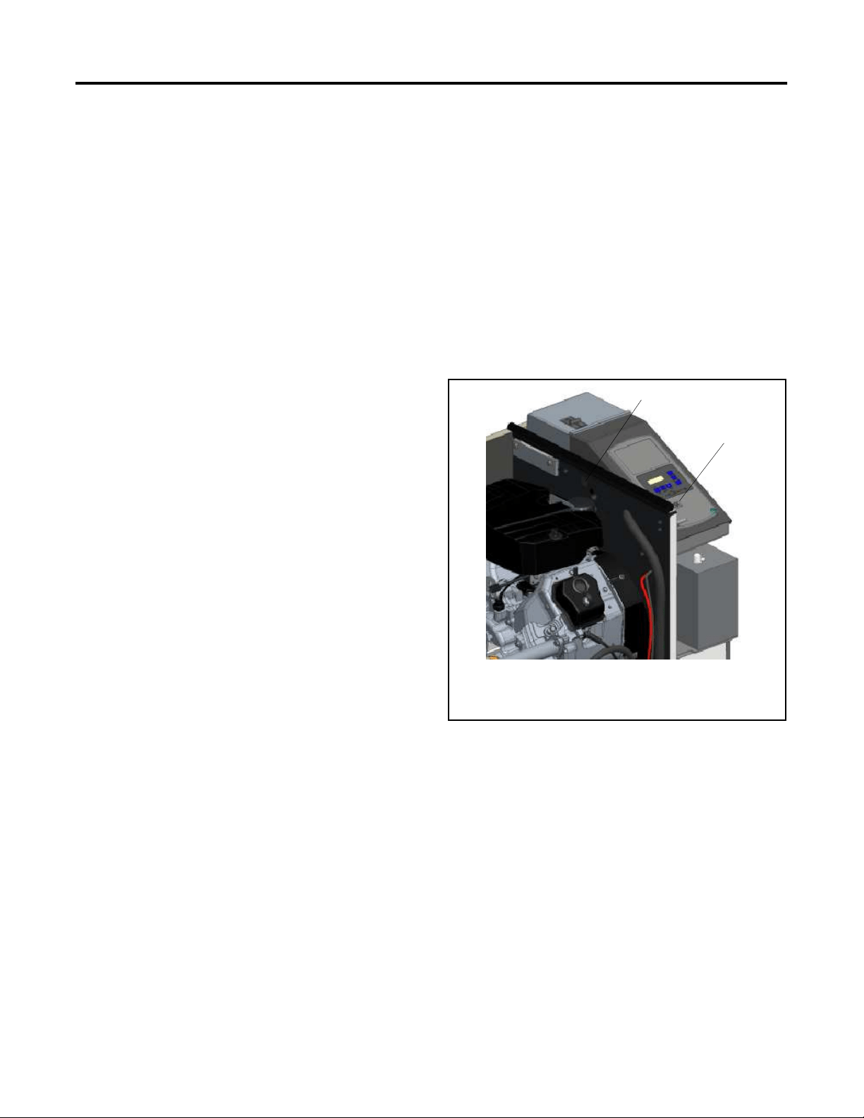
5.4 USB Port and Auxiliary
Winding Mini-Breaker
The USB port is located under a small rubber cover as
shown in Figure 5-1. The alternator winding circuit
breaker is located on the engine side of the bulkhead as
shown in Figure 5-1.
A personal computer (laptop) with Kohler SiteTech
software can be used to view the event history and
adjust controller settings. Use a USB cable with a mini-B
connector to connect the controller’s USB port to your
PC.
See TP-6701, SiteTech Software Operation Manual,
for software operation instructions.
1
1. Mini-breaker location (access through engine compartment)
2. USB port on RDC2 controller
ADV-8928
2
Figure 5-1 USB Port and Mini-Breaker Locations
5.5 Stop Switches
The generator set may be equipped with an optional
emergency stop switch or an engine shutdown switch.
Verify that it is safe to start the generator set and apply
power to the load before deactivating these switches.
See Section 2.3.4.
Loading ...
Loading ...
Loading ...