

ENGLISH
1.
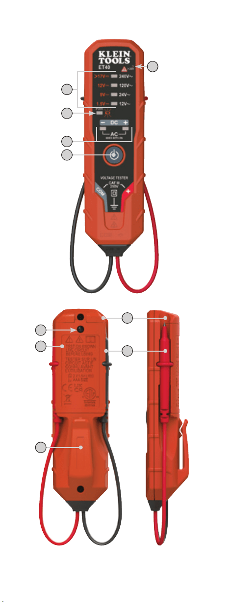
Power On/Off Button
2.
Power On / Low Battery Indicator
3.
Voltage Level Indicators
4.
DC Polarity Indicators (AC when both illuminated)
5.
Hazardous Voltage Indicator
6.
Test Leads
7.
Battery Compartment Door
8.
Battery Compartment Screw
9.
Pocket Clip
10.
Test Lead Holders
NOTE: There are no user-serviceable parts inside tester.
1.
Botón de encendido y apagado
2.
Indicador de encendido y batería baja
3.
Indicadores de nivel de voltaje
4.
Indicadores de polaridad de CD (CA cuando ambos están encendidos)
5.
Indicador de voltaje peligroso
6.
Cables de prueba
7.
Tapa del compartimento de las baterías
8.
Tornillo del compartimento de lasbaterías
9.
Clip de bolsillo
10.
Soportes para cables de prueba
NOTA: El probador no contiene en su interior piezas que el usuario pueda
reparar.
ESPAÑOL
1.
Bouton marche/arrêt
2.
Indicateur de mise sous tension/piles faibles
3.
Indicateurs de niveau detension
4.
Indicateurs de polarité c.c.(DC) (c.a. [AC] lorsque les deux sont allumés)
5.
Indicateur de tension dangereuse
6.
Fils de test
7.
Couvercle du compartiment à piles
8.
Vis du compartiment àpiles
9.
Agrafe pour poche
10.
Porte‑fils de test
REMARQUE: Ce testeur ne contient aucune pièce réparable par
l’utilisateur.
FRANÇAIS
1
7
9
8
10
6
2
5
3
4
Symbols on tester / Símbolos del probador / Symboles sur le
testeur
Warning – Risk of electric shock / Advertencia: riesgo de choque
eléctrico / Avertissement – Risque d'électrocution
Risk of danger. Important information: It is important that users
of this tester read, understand, and follow all warnings, cautions,
safety information, and instructions in this manual before operating
or servicing this tester. Failure to follow instructions could result in
death or serious injury.
Riesgo de peligro. Información importante: Es importante que
el usuario de este probador lea, comprenda y respete todas las
advertencias, precauciones, instrucciones e información de seguridad
incluidas en este manual, antes de poner en funcionamiento el
probador o de realizarle servicios de mantenimiento. No seguir estas
instrucciones puede dar lugar a lesiones graves o mortales.
Risque de danger. Information importante: Il est important que
les utilisateurs de
ce testeur lisent, comprennent et suivent tous
les avertissements, mises en garde, informations
de sécurité et
instructions donnés dans le présent guide avant de faire fonctionner
ou de réparer ce testeur. Le non‑respect pourrait entraîner des
blessures graves, voire la mort.
Read instructions /Lea las instrucciones / Lire les instructions
Double insulated / Doble aislamiento / Double isolation
AC Voltage / Voltaje CA / Tension c.a.
DC Voltage / Voltaje CD / Tension c.c.
COM
Negative Lead Input / Entrada de conductor negativo / Entrée négative
pour fil
Positive Lead Input / Entrada de conductor positivo / Entrée positive
pour fil
ET40
Electronic AC/DC Voltage Tester –
Instructions
Probador electrónico devoltaje CA/CD –
Instrucciones
Testeur de tension c.a./c.c. électronique–
Instructions
BASED ON 1390428 Rev. 10‑21 G
ENGLISH
1.
Power On/Off Button
2.
Power On / Low Battery Indicator
3.
Voltage Level Indicators
4.
DC Polarity Indicators (AC when both illuminated)
5.
Hazardous Voltage Indicator
6.
Test Leads
7.
Battery Compartment Door
8.
Battery Compartment Screw
9.
Pocket Clip
10.
Test Lead Holders
NOTE: There are no user-serviceable parts inside tester.
1.
Botón de encendido y apagado
2.
Indicador de encendido y batería baja
3.
Indicadores de nivel de voltaje
4.
Indicadores de polaridad de CD (CA cuando ambos están encendidos)
5.
Indicador de voltaje peligroso
6.
Cables de prueba
7.
Tapa del compartimento de las baterías
8.
Tornillo del compartimento de lasbaterías
9.
Clip de bolsillo
10.
Soportes para cables de prueba
NOTA: El probador no contiene en su interior piezas que el usuario pueda
reparar.
ESPAÑOL
1.
Bouton marche/arrêt
2.
Indicateur de mise sous tension/piles faibles
3.
Indicateurs de niveau detension
4.
Indicateurs de polarité c.c.(DC) (c.a. [AC] lorsque les deux sont allumés)
5.
Indicateur de tension dangereuse
6.
Fils de test
7.
Couvercle du compartiment à piles
8.
Vis du compartiment àpiles
9.
Agrafe pour poche
10.
Porte‑fils de test
REMARQUE: Ce testeur ne contient aucune pièce réparable par
l’utilisateur.
FRANÇAIS
1
7
9
8
10
6
2
5
3
4
Symbols on tester / Símbolos del probador / Symboles sur le
testeur
Warning – Risk of electric shock / Advertencia: riesgo de choque
eléctrico / Avertissement – Risque d'électrocution
Risk of danger. Important information: It is important that users
of this tester read, understand, and follow all warnings, cautions,
safety information, and instructions in this manual before operating
or servicing this tester. Failure to follow instructions could result in
death or serious injury.
Riesgo de peligro. Información importante: Es importante que
el usuario de este probador lea, comprenda y respete todas las
advertencias, precauciones, instrucciones e información de seguridad
incluidas en este manual, antes de poner en funcionamiento el
probador o de realizarle servicios de mantenimiento. No seguir estas
instrucciones puede dar lugar a lesiones graves o mortales.
Risque de danger. Information importante: Il est important que
les utilisateurs de
ce testeur lisent, comprennent et suivent tous
les avertissements, mises en garde, informations
de sécurité et
instructions donnés dans le présent guide avant de faire fonctionner
ou de réparer ce testeur. Le non‑respect pourrait entraîner des
blessures graves, voire la mort.
Read instructions /Lea las instrucciones / Lire les instructions
Double insulated / Doble aislamiento / Double isolation
AC Voltage / Voltaje CA / Tension c.a.
DC Voltage / Voltaje CD / Tension c.c.
COM
Negative Lead Input / Entrada de conductor negativo / Entrée négative
pour fil
Positive Lead Input / Entrada de conductor positivo / Entrée positive
pour fil
ET40
Electronic AC/DC Voltage Tester –
Instructions
Probador electrónico devoltaje CA/CD –
Instrucciones
Testeur de tension c.a./c.c. électronique–
Instructions
BASED ON 1390428 Rev. 10‑21 G

ENGLISH
WARNINGS
To ensure safe operation and service of the tester, follow these
instructions. Failure to observe these warnings can result in severe injury
or death.
• Before each use verify tester operation by measuring a known voltage.
• Never use the tester on a circuit with voltages that exceed the category
based rating of this tester.
• Do not use the tester during electrical storms or in wet weather.
• Do not use the tester or test leads if they appear to be damaged.
• Keep fingers behind the finger guards and away from the metal probe
contacts when making measurements.
• Use caution when working with voltages above 25V AC RMS or 60V
DC. Such voltages pose a shock hazard.
• Always adhere to local and national safety codes. Use personal
protective equipment to prevent shock and arc blast injury where
hazardous live conductors are exposed.
• Tester is IP41 dust & water resistant. Following any contact with water,
thoroughly dry tester prior to subsequent use.
CAUTION
• DO NOT attempt to repair this tester. It contains no serviceable parts.
• DO NOT expose tester to extremes in temperature or high humidity.
OPERATING INSTRUCTIONS
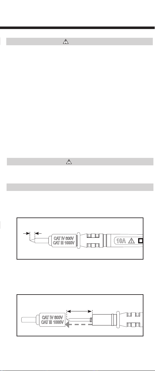
TESTING IN CAT III MEASUREMENT LOCATIONS
Ensure the test lead shield is pressed firmly in place. Failure to use the
CATIII shield increases arc‑flash risk.
TESTING IN CAT II MEASUREMENT LOCATIONS
CAT III shields may be removed for CAT II locations. This will allow testing
on recessed conductors such as standard wall outlets. Take care not to lose
the shields.
ELECTRICAL SPECIFICATIONS
• Voltage Level Indicators:
• AC: 12V, 24V, 120V, 240V
• DC: 1.5V, 9V, 12V, >17V
• DC Polarity Indicators: DC Positive, DC Negative,
both illuminated indicates AC
• Hazardous Voltage Indicator:
• Continuously on when voltage >25V AC or >25V DC
• Blinking at ~2Hz when voltage >240V AC or >60V DC
• AC Frequency: 50Hz / 60Hz
• Input Protection: 250V AC/DC
• Maximum Measurable Voltage: 240V AC (240V AC Indicator)
or 24V DC (>17V DC Indicator)
• Accuracy: Voltage level indicators typically illuminate fully at approx.
70% to 100% of indicated voltage, except for 12V DC (84% to 100%)
and >17V DC (94% to 100% of 17V)
• Auto Power-OFF : After 2 minutes of inactivity
Specifications subject to change.
GENERAL SPECIFICATIONS
• Operating Altitude: Up to 6562 ft. (2000 m)
• Relative Humidity: <85% non‑condensing
• Operating Temperature: 5° to 113°F (‑15° to 45°C)
• Storage Temperature: ‑4° to 140°F (‑20° to 60°C)
• Batteries: 2x AAA 1.5V Alkaline
• Dimensions: 5.24" x 1.52" x 1.11" (133 x 39 x 28 mm)
• Weight: 3.1 oz. (90 g) including batteries
• Calibration: Accurate for one year
• Standards:
EN61326‑1:2013, EN61326‑2:2013, EN61010‑1:2010,
EN61010‑2‑030:2010, EN61010‑031:2015
Conforms to UL STD. 61010‑1, 61010‑2‑030 and 61010‑031.
Certified to CSA STD. C22.2 NO. 61010‑1, 61010‑2‑030
and 61010‑031.
• Pollution degree: 2
• Drop Protection: 9.8 ft. (3 m)
• Ingress Protection: IP41
• Safety Rating: CAT III 250V, Class 2, double insulation
CAT III: Measurement category III is applicable to test and
measuring circuits connected to the distribution part of the
building’s low‑voltage MAINS installation.
• Electromagnetic Environment: This equipment meets requirements
for use in basic and controlled electromagnetic environments
like residential properties, business premises, and light‑industrial
locations.
Specifications subject to change.
5001748
OPERATING INSTRUCTIONS
Press and hold the On/Off button
1
for approx. 1 second to turn the tester on or
off. When on, the Power/Low Battery indicator
2
will be continuously illuminated.
The tester will automatically power‑OFF following 2 minutes of inactivity to conserve
battery life.
Apply test leads
6
to the system under test to measure voltage. The Voltage
Level Indicators
3
will illuminate indicating the voltage present. When DC
voltage is detected, the "+" or "–" polarity indicator
4
will illuminate, revealing
the polarity. When AC voltage is detected, both polarity indicators will illuminate.
CLEANING
Ensure tester is turned off and wipe with a clean, dry lint‑free cloth.
Do not use abrasive cleaners or solvents.
STORAGE
Remove the batteries when not in use for a prolonged period of time. Do
not expose to high temperatures or humidity. After a period of storage
in extreme conditions exceeding the limits mentioned in the General
Specifications section, allow the tester to return to normal operating
conditions before using.
DISPOSAL / RECYCLE
Do not place equipment and its accessories in the trash. Items must
be properly disposed of in accordance with local regulations. Please
see www.epa.gov or www.erecycle.org for additional information.
CUSTOMER SERVICE
KLEIN TOOLS, INC.
450 Bond Street, Lincolnshire, IL 60069 1‑800‑553‑4676
BATTERY REPLACEMENT
When the Power‑ON / Low Battery indicator
2
blinks, the batteries must be replaced.
1. Remove screw
8
from battery compartment door
7
.
2. Remove and recycle spent batteries.
3. Install two new AAA batteries. Note proper polarity.
4. Replace battery door and fasten securely with screw.
DO NOT attempt to measure AC voltages in excess of 240V AC, or DC
voltages in excess of 25V DC under any circumstances. The hazardous
voltage indicator will illuminate in the presence of voltage exceeding
25V AC or DC, with characteristics as detailed in the table below.
To avoid risk of electric shock, disconnect leads from any voltage
source before removing battery door.
To avoid risk of electric shock, do not operate tester while battery
door is removed.
HAZARDOUS VOLTAGE
INDICATOR STATUS
AC VOLTAGE DC VOLTAGE
Solid on >25V AC >25V DC
Blinking at approx. 2Hz >240V AC >60V DC
0.7" (18 mm)
5/32"
(4 mm)
5/32"
(4 mm)
ENGLISH
WARNINGS
To ensure safe operation and service of the tester, follow these
instructions. Failure to observe these warnings can result in severe injury
or death.
• Before each use verify tester operation by measuring a known voltage.
• Never use the tester on a circuit with voltages that exceed the category
based rating of this tester.
• Do not use the tester during electrical storms or in wet weather.
• Do not use the tester or test leads if they appear to be damaged.
• Keep fingers behind the finger guards and away from the metal probe
contacts when making measurements.
• Use caution when working with voltages above 25V AC RMS or 60V
DC. Such voltages pose a shock hazard.
• Always adhere to local and national safety codes. Use personal
protective equipment to prevent shock and arc blast injury where
hazardous live conductors are exposed.
• Tester is IP41 dust & water resistant. Following any contact with water,
thoroughly dry tester prior to subsequent use.
CAUTION
• DO NOT attempt to repair this tester. It contains no serviceable parts.
• DO NOT expose tester to extremes in temperature or high humidity.
OPERATING INSTRUCTIONS
TESTING IN CAT III MEASUREMENT LOCATIONS
Ensure the test lead shield is pressed firmly in place. Failure to use the
CATIII shield increases arc‑flash risk.
TESTING IN CAT II MEASUREMENT LOCATIONS
CAT III shields may be removed for CAT II locations. This will allow testing
on recessed conductors such as standard wall outlets. Take care not to lose
the shields.
ELECTRICAL SPECIFICATIONS
• Voltage Level Indicators:
• AC: 12V, 24V, 120V, 240V
• DC: 1.5V, 9V, 12V, >17V
• DC Polarity Indicators: DC Positive, DC Negative,
both illuminated indicates AC
• Hazardous Voltage Indicator:
• Continuously on when voltage >25V AC or >25V DC
• Blinking at ~2Hz when voltage >240V AC or >60V DC
• AC Frequency: 50Hz / 60Hz
• Input Protection: 250V AC/DC
• Maximum Measurable Voltage: 240V AC (240V AC Indicator)
or 24V DC (>17V DC Indicator)
• Accuracy: Voltage level indicators typically illuminate fully at approx.
70% to 100% of indicated voltage, except for 12V DC (84% to 100%)
and >17V DC (94% to 100% of 17V)
• Auto Power-OFF : After 2 minutes of inactivity
Specifications subject to change.
GENERAL SPECIFICATIONS
• Operating Altitude: Up to 6562 ft. (2000 m)
• Relative Humidity: <85% non‑condensing
• Operating Temperature: 5° to 113°F (‑15° to 45°C)
• Storage Temperature: ‑4° to 140°F (‑20° to 60°C)
• Batteries: 2x AAA 1.5V Alkaline
• Dimensions: 5.24" x 1.52" x 1.11" (133 x 39 x 28 mm)
• Weight: 3.1 oz. (90 g) including batteries
• Calibration: Accurate for one year
• Standards:
EN61326‑1:2013, EN61326‑2:2013, EN61010‑1:2010,
EN61010‑2‑030:2010, EN61010‑031:2015
Conforms to UL STD. 61010‑1, 61010‑2‑030 and 61010‑031.
Certified to CSA STD. C22.2 NO. 61010‑1, 61010‑2‑030
and 61010‑031.
• Pollution degree: 2
• Drop Protection: 9.8 ft. (3 m)
• Ingress Protection: IP41
• Safety Rating: CAT III 250V, Class 2, double insulation
CAT III: Measurement category III is applicable to test and
measuring circuits connected to the distribution part of the
building’s low‑voltage MAINS installation.
• Electromagnetic Environment: This equipment meets requirements
for use in basic and controlled electromagnetic environments
like residential properties, business premises, and light‑industrial
locations.
Specifications subject to change.
5001748
OPERATING INSTRUCTIONS
Press and hold the On/Off button
1
for approx. 1 second to turn the tester on or
off. When on, the Power/Low Battery indicator
2
will be continuously illuminated.
The tester will automatically power‑OFF following 2 minutes of inactivity to conserve
battery life.
Apply test leads
6
to the system under test to measure voltage. The Voltage
Level Indicators
3
will illuminate indicating the voltage present. When DC
voltage is detected, the "+" or "–" polarity indicator
4
will illuminate, revealing
the polarity. When AC voltage is detected, both polarity indicators will illuminate.
CLEANING
Ensure tester is turned off and wipe with a clean, dry lint‑free cloth.
Do not use abrasive cleaners or solvents.
STORAGE
Remove the batteries when not in use for a prolonged period of time. Do
not expose to high temperatures or humidity. After a period of storage
in extreme conditions exceeding the limits mentioned in the General
Specifications section, allow the tester to return to normal operating
conditions before using.
DISPOSAL / RECYCLE
Do not place equipment and its accessories in the trash. Items must
be properly disposed of in accordance with local regulations. Please
see www.epa.gov or www.erecycle.org for additional information.
CUSTOMER SERVICE
KLEIN TOOLS, INC.
450 Bond Street, Lincolnshire, IL 60069 1‑800‑553‑4676
[email protected] www.kleintools.com
BATTERY REPLACEMENT
When the Power‑ON / Low Battery indicator
2
blinks, the batteries must be replaced.
1. Remove screw
8
from battery compartment door
7
.
2. Remove and recycle spent batteries.
3. Install two new AAA batteries. Note proper polarity.
4. Replace battery door and fasten securely with screw.
DO NOT attempt to measure AC voltages in excess of 240V AC, or DC
voltages in excess of 25V DC under any circumstances. The hazardous
voltage indicator will illuminate in the presence of voltage exceeding
25V AC or DC, with characteristics as detailed in the table below.
To avoid risk of electric shock, disconnect leads from any voltage
source before removing battery door.
To avoid risk of electric shock, do not operate tester while battery
door is removed.
HAZARDOUS VOLTAGE
INDICATOR STATUS
AC VOLTAGE DC VOLTAGE
Solid on >25V AC >25V DC
Blinking at approx. 2Hz >240V AC >60V DC
0.7" (18 mm)
5/32"
(4 mm)
5/32"
(4 mm)
