
Loading ...
Loading ...
Loading ...
Questions? Call Toll Free at 1-800-737-2112 Copyright © 2019 MAT Engine Technologies, LLC
ENG - 7
WARNING
Read and follow the assembly instructions. Do not discard any parts or materials until the unit is assembled.
References to the right or left side of the blower are from the viewpoint of the operator’s position behind the blower.
WARNING
Do not operate blower if it is damaged or not completely and correctly assembled.
WARNING
Before doing any assembly or maintenance to the unit, remove the wire from the spark plug.
WARNING
Always wear ANSI compliant safety glasses with side shields while assembling the blower.
Assembly
• Save all instructions
If you need assistance or find any parts missing,
CALL TOLL FREE: 1-800-737-2112.
Parts Included With the Packaged Blower
Tools Needed for Assembly
Unpacking
• Operator’s Manual
• Upper and Middle Handles
• Blower Assembly with Tube
• Discharge Nozzle
• 50:1 2-Cycle Engine Oil (2.6 Fluid Ounces)
• Spark Plug Wrench and 5mm Hex Wrench
• (2) Wheel Assemblies
• (2) Wheel Hex Bolts
• (4) Washers For Wheel Bolts
• (2) Plastic Wing Nuts (For Attaching Handles)
• (2) Saddle Bolts (For Attaching Handles)
• (2) Hex Flange Screws, M6 x 35 (For Attaching
Lower Handle)
• (2) Hex Lock Nuts, M6 (For Attaching Lower Handle)
WARNING
Do not operate blower if it is damaged or not securely and fully assembled.
• 10 mm wrench or adjustable wrench
• 12 mm socket or open wrench
1. Remove components from carton.
2. Remove foam and corrugated protection
1. Install straight round middle handle to lower handle
and secure using two M6 x 35 hex bolts and locknuts. (Fig. 1)
2. Route throttle cable through legs of upper handle. Install upper handle
to middle handle and secure using two saddle bolts and plastic knobs. Install saddle
bolts from opposing sides so plastic knobs will not interfere with each other. Orient
handle so the “V” shape is upward. Tighten knobs securely.
(Fig. 2)
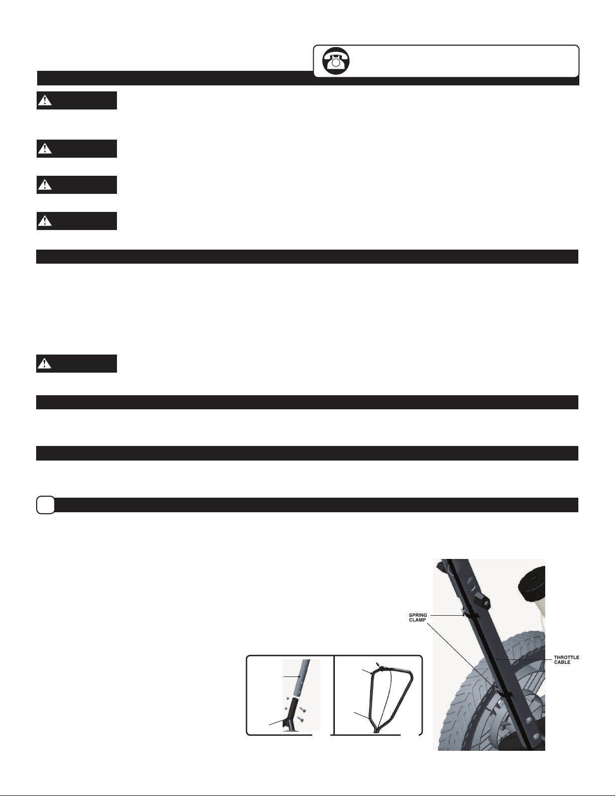
3. Secure throttle cable to the underside of the middle
handle using the two spring clamps which have been
installed at the factory. (Fig. 3) Inspect throttle cable to
assure generous loops. Do not kink cable.
LOWER
HANDLE
MIDDLE
HANDLE
UPPER
HANDLE
MIDDLE
HANDLE
Fig. 1
Fig. 2
Fig. 3
Handle Assembly
A
Loading ...
Loading ...
Loading ...