Loading ...
Loading ...
Loading ...
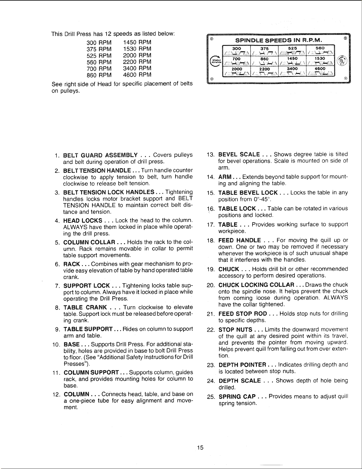
This Drill Press has 12 speeds as listed below:
300 RPM 1450 RPM
375 RPM 1530 RPM
525 RPM 2000 RPM
560 RPM 2200 RPM
700 RPM 3400 RPM
860 RPM 4600 RPM
See right side of Head for specific placement of belts
on pulleys.
SPINDLE SPEEDS iN R.P, Mo
300 375
_._ 700 860
2000 2200
®
-- 5zs sac
1450 1530
4600
®
1. BELT GUARD ASSEMBLY . . . Covers pulleys
and belt during operation of drill press.
2. BELT TENSION HANDLE... Turn handle counter
clockwise to apply tension to belt, turn handle
clockwise to release belt tension.
3. BELT TENSION LOCK HANDLES... Tightening
handles locks motor bracket support and BELT
TENSION HANDLE to maintain correct belt dis-
tance and tension.
4. HEAD LOCKS... Lock the head to the column.
ALWAYS have them locked in place while operat-
ing the drill press.
5. COLUMN COLLAR... Holds the rack to the col-
umn. Rack remains movable in collar to permit
table support movements.
6. RACK... Combines with gear mechanism to pro-
vide easy elevation of table by hand operated table
crank.
7. SUPPORT LOCK... Tightening locks table sup-
port to column. Always have it locked in place while
operating the Drill Press.
8. TABLE CRANK . . . Turn clockwise to elevate
table. Support lock must be released before operat-
ing crank.
9. TABLE SUPPORT... Rides on column to support
arm and table.
10. BASE. o, Supports Drill Press. For additional sta-
bility, holes are provided in base to bolt Drill Press
to floor. (See "Additional Safety Instructions for Drill
Presses").
11. COLUMN SUPPORT... Supports column, guides
rack, and provides mounting holes for column to
base.
12. COLUMN... Connects head, table, and base on
a one-piece tube for easy alignment and move-
ment.
13. BEVEL SCALE... Shows degree table is tilted
for bevel operations. Scale is mounted on side of
arm.
14. ARM... Extends beyond table support for mount-
ing and aligning the table.
!5. TABLE BEVEL LOCK... Locks the table in any
position from 0°-45°.
16, TABLE LOCK... Table can be rotated in various
positions and locked.
17. TABLE... Provides working surface to support
workpiece.
18. FEED HANDLE .. . For moving the quill up or
down. One or two may be removed if necessary
whenever the workpiece is of such unusual shape
that it interferes with the handles.
19. CHUCK o.. Holds drill bit or other recommended
accessory to perform desired operations.
20. CHUCK LOCKING COLLAR... Draws the chuck
onto the spindle nose. It helps prevent the chuck
from coming loose during operation. ALWAYS
have the collar tightened.
21. FEED STOP ROD... Holds stop nuts for drilling
to specific depths.
22. STOP NUTS... Limits the downward movement
of the quill at any desired point within its travet,
and prevents the pointer from moving upward.
Helps prevent quill from falling out from over exten-
tion.
23. DEPTH POINTER... Indicates drilling depth and
is located between stop nuts.
24. DEPTH SCALE . . . Shows depth of hole being
drilled.
25. SPRING CAP.. •Provides means to adjust quill
spring tension.
!5
Loading ...
Loading ...
Loading ...