Loading ...
Loading ...
Loading ...
39 - English
ADJUSTMENTS
After installation, adjust the rip scale indicator to account
for the kerf and thickness of the blade. Refer to To Set the
Rip Fence Scale Indicator to the Blade in the Operation
section of this manual. In cutting operations, the scale will be
set to the side of the blade where the cut will be measured
and made.
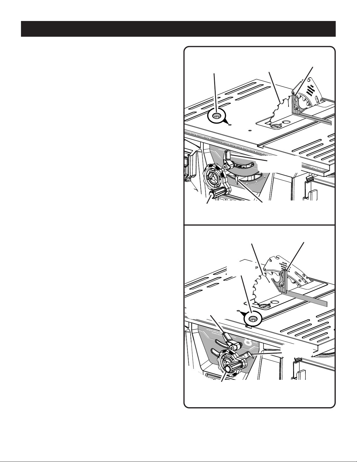
TO SET THE BLADE AT 0° AND 45°
See Figures 54 - 55.
The angle settings of the saw have been set at the factory
and, unless damaged in shipping, should not require setting
during assembly. After extensive use, they may need to be
checked.
Remove the battery.
Raise the blade.
Remove the blade guard assembly with kickback pawls.
To check for squareness, 0˚ bevel:
Unlock the bevel locking lever.
Rotate the height/bevel adjusting handwheel until the
blade is tilted to the right as far as it will go.
Lock the bevel locking lever.
Place the combination square against blade. Make sure
square is not touching the tip of one of the saw teeth.
If the blade is not an exact 90° (0° bevel):
Unlock the bevel locking lever.
Turn the height/bevel adjusting handwheel until the bevel
indicator points to 5°-10°.
Turn the 0° stop screw 1/4 turn in the clockwise or
counterclockwise direction.
Rotate the height/bevel adjusting handwheel until the
blade is tilted to the right as far as it will go.
Lock the bevel locking lever and check the blade angle.
Repeat above steps to readjust and recheck blade angle
as needed.
Once blade is square to the table (0° bevel):
Check bevel indicator.
If indicator is not pointing to the 0º mark on the bevel
scale, loosen the indicator adjusting screw and adjust
indicator.
Retighten screw.
To check for squareness, 45˚ bevel:
Unlock the bevel locking lever.
Rotate the height/bevel adjusting handwheel until the
blade is tilted to the left as far as it will go.
Lock the bevel locking lever.
Place the combination square against blade. Make sure
square is not touching the tip of one of the saw teeth.
If the blade is not an exact 45°:
Unlock the bevel locking lever.
Turn the height/bevel adjusting handwheel until the bevel
indicator points to 35°-40°.
Turn the 45° stop screw 1/4 turn in the clockwise or
counterclockwise direction.
Fig. 54
BEVEL
INDICATOR
45˚ STOP
SCREW
COMBINATION
SQUARE
BLADE
BEVEL
LOCKING LEVER
Fig. 55
HEIGHT/BEVEL
ADJUSTING HANDWHEEL
Rotate the height/bevel adjusting handwheel until the
blade is tilted to the left as far as it will go.
Lock the bevel locking lever and check the blade angle.
HEIGHT/BEVEL
ADJUSTING
HANDWHEEL
BEVEL
INDICATOR
BEVEL
LOCKING LEVER
COMBINATION
SQUARE
BLADE
0˚ STOP
SCREW
Loading ...
Loading ...
Loading ...