Loading ...
Loading ...
Loading ...
29 - English
Remove the battery.
Loosen the rip fence by lifting the locking lever.
Using a framing square, set the rip fence 2 in. from the
blade tip edge.
Loosen the screw on the scale indicator and align with
the 2 in. mark as shown.
Tighten the screw and check the dimension and the rip
fence.
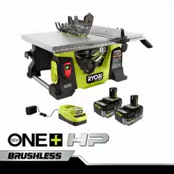
TO USE THE MITER GAUGE
See Figure 35.
The miter gauge provides greater accuracy in angled cuts.
For very close tolerances, test cuts are recommended.
The miter gauge can be turned 60° to the right or left.
Loosen the lock knob.
With the miter gauge in the miter gauge groove, rotate
the gauge until the desired angle is reached on the scale.
Retighten the lock knob.
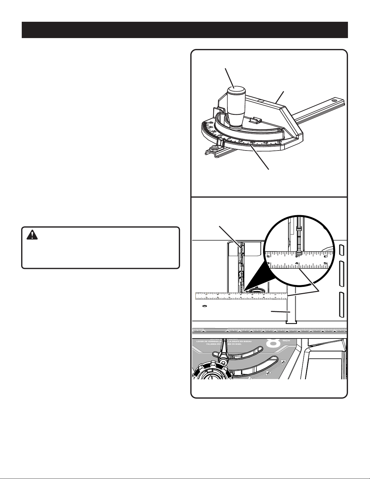
ADJUSTING THE BLADE PARALLEL TO THE
MITER GAUGE GROOVE (REMOVING HEEL)
See Figures 36 - 38.
WARNING:
The blade must be made parallel to the miter gauge
groove so the wood does not bind resulting in kickback.
Failure to do so could result in serious personal injury.
Do not loosen any bolts for this adjustment until you have
checked with a ruler and made test cuts to be sure adjust-
ments are necessary. Once the bolts are loosened, these
items must be reset.
Remove the battery.
Remove the blade guard and riving knife. Raise the blade
by turning the height/bevel adjusting handwheel clock-
wise.
NOTE: For details on removing and reinstalling the riving
knife, see Cleaning the Riving Knife Lock Lever Plates
in the Maintenance section of this manual.
Mark beside one of the blade teeth at the front of the
blade. Using a ruler, measure the distance from the inside
face of the blade tooth to the left edge of the miter gauge
groove.
NOTE: For greater accuracy, place the marked blade
tooth on top of the ruler.
Turn the blade so the marked tooth is at the back.
Move the ruler to the rear and again measure the distance
from the inside face of the blade tooth to the left edge of
the miter gauge groove. If the distances are the same,
the blade and the miter gauge groove are parallel.
Replace blade guard and riving knife.
OPERATION
Fig. 36
Fig. 35
LOCK
KNOB
MITER
GAUGE BODY
MITER
GAUGE
MITER GAUGE
GROOVE
RULER
BLADE
TOOTH
If the distances are different:
Remove the blade guard and riving knife. Raise the
blade by turning the height/bevel adjusting handwheel
clockwise.
Loosen the locking bolts by turning towards the left.
Loading ...
Loading ...
Loading ...