
Loading ...
Loading ...
Loading ...
4
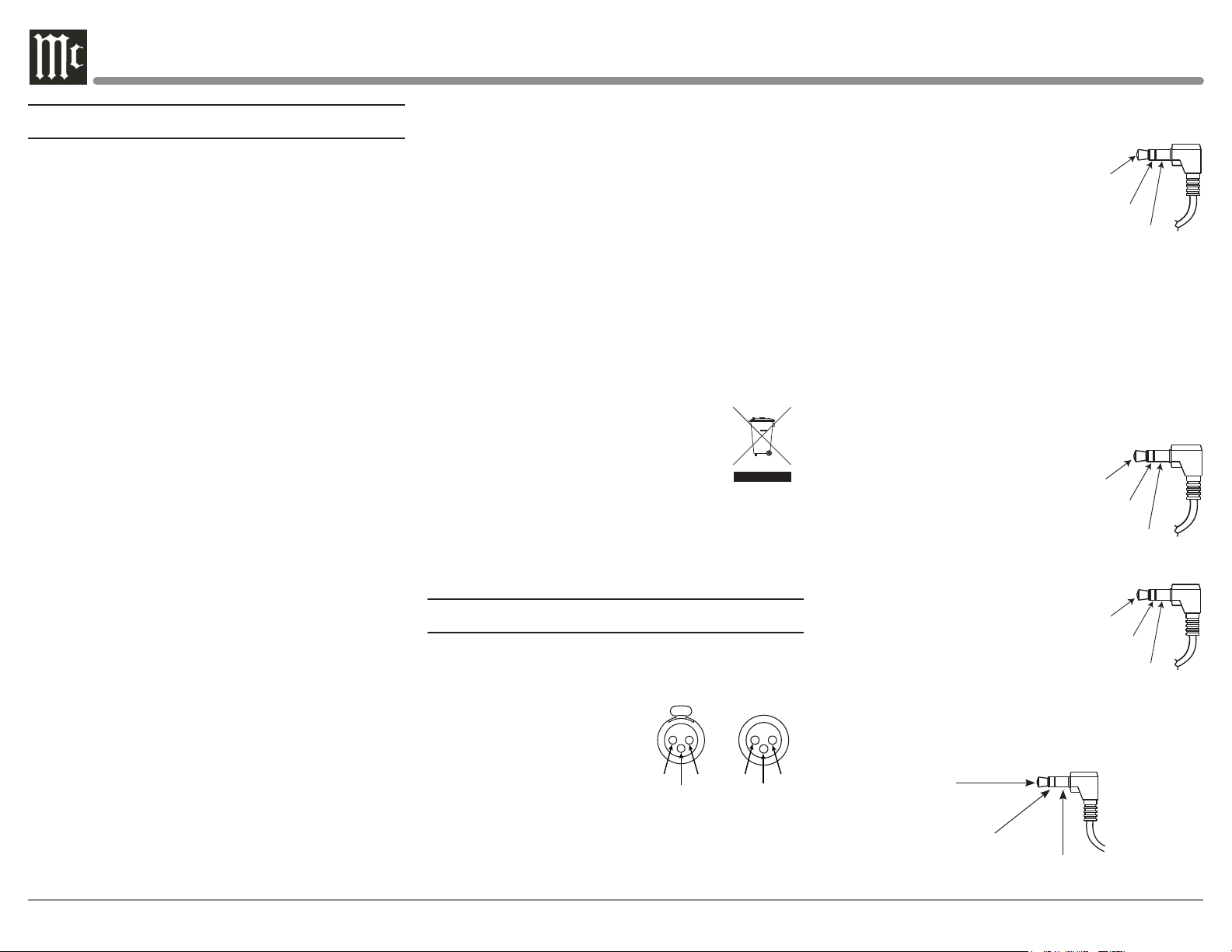
Tip: C12000 TXD Out
Data Being Transmitted from C12000
Data
Signal
N/C
Data
Ground
PIN 2 PIN 1
PIN 3
PIN 1
PIN 2
PIN 3
General Information
1.
The C12000 System consists of two separate chassis;
a “Controller” and a “Preamplifier”. When specific
clarification is necessary for instruction, the separate
chassis will be referenced individually with their
corresponding names. Otherwise, “C12000” will be
used to reference the unit as a whole.
2. For additional connection information, refer to the
owner’s manual(s) for any component(s) connected to
the C12000 Audio Preamplifier.
3. The Main AC Power going to the C12000 and
any other McIntosh Component(s) should not
be applied until all the system components are
connected together. Failure to do so could result in
malfunctioning of some or all of the system’s normal
operations. When the C12000 and other McIntosh
Components are in their Standby Power Off Mode, the
Microprocessor’s Circuitry inside each component is
active and communication is occurring between them.
4. Balanced and Unbalanced Inputs and Outputs can be
mixed. For example, you may connect signal sources
to Unbalanced Inputs and send signals from the
Balanced Outputs. You can also use Balanced and
Unbalanced Outputs simultaneously, connected to
different Power Amplifiers.
5. Sound Intensity is measured in units called Decibels
and “dB” is the abbreviation.
6. The McIntosh C12000 is factory configured for
immediate use. It can also be customized to comple-
ment the components making up your system. Refer
to the C12000 “Setup Mode” starting on Page 20 for
additional information.
7. The Remote Control Supplied with the C12000
is capable of operating other components. For
additional information go to
www.mcintoshlabs.com.
Power
Control
Meter
Illumination
Control
Ground
Main, Triggers 1-4
and PASSTHRU
8. The IR Input, with a 3.5mm mini phone jack, is
configured for non-McIntosh IR sensors such as
a Xantech Model HL85BK Kit. Use a Connection
Block such as a Xantech Model ZC21 when two
or more IR sensors need to be connected to the
C12000. The signal from a connected External IR
Sensor will have priority over the signal from the
Front Panel IR Sensor.
9. Controller to Preamplier Cable Part No. 171872 is
three foot, shielded 23 conductor, male-to-female
custom cable. Two cables are required between
Controller and Preamplier.
Do not use any other cable when connecting the
C12000 Controller to the C12000 Preamplier.
10. When discarding the unit, comply with
local rules or regulations. Batteries
should never be thrown away or incin-
erated but disposed of in accordance
with the local regulations concerning
battery disposal.
11. For additional information on the C12000 and
other McIntosh Products please visit the McIntosh
Web Site at www.mcintoshlabs.com.
Connector and Cable Information
XLR Connectors
Below is the Pin configuration for the XLR Balanced
Input and Output Connectors on the C12000. Refer to
the diagrams for connections:
PIN 1: Shield/Ground
PIN 2: + Output
PIN 3: - Output
Power Control and Trigger Connectors
The C12000 Power Control Out, Trigger and
PASSTHRU Output Jacks send Power On/Off Signals
(+12 volt/0 volt) when connected to other McIntosh
IR Data
Control
Ground
N/C
Components. An additional connec-
tion is for controlling the illumina-
tion of the Power Output Meters on
McIntosh Power Amplifiers.
A 3.5mm stereo mini phone plug
is used for connection to the Power
Control, Trigger and PASSTHRU
Outputs on the C12000.
Note: The Power Control, Trigger, PASSTHRU and Data
Connecting Cable is available from the McIntosh
Parts Department:
Power Control, Trigger, PASSTHRU and Data
Cable Part No. 170202
Six foot, shielded 2 conductor, with 3.5mm stereo
mini phone plugs on each end.
Data Port Connectors
The C12000 Data Out Ports
send Remote Control Signals to
Source Components. A 3.5mm
stereo mini phone plug is used
for connection.
IR IN Port Connectors
The IR IN Port also uses a 3.5mm
stereo mini phone plug and allows
the connection of other brand IR
Receivers to the C12000.
RS232 Port Connector
The RS232 Port uses a 3.5mm stereo mini phone plug
to connect to external third-party controllers.
Ring: C12000 RXD In
Data Being Received by C12000
Ground
Loading ...
Loading ...
Loading ...