
Loading ...
Loading ...
Loading ...
10
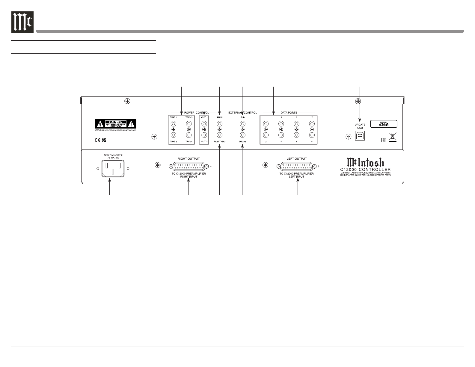
Navigating the Rear Panel (Controller)
1CR
2CR 3CR 4CR 5CR 6CR
7CR 8CR 9CR 10CR 11CR
1CR POWER CONTROL TRIGger outputs 1 thru 4 are
assignable to send turn On/Off signals to components
2CR POWER CONTROL OUT 1 and 2 send turn On/Off
signals to a McIntosh Component when Output 1 and
2 are activated
3CR POWER CONTROL MAIN Output sends turn On/Off
signals to a McIntosh Component when the C12000
Controller is switched On/Off
4CR IR INput for signals from a compatible IR Sensor for
Remote Control use
5CR DATA PORTS are assignable to send signals to
Source Components to allow control with the C12000
Controller Remote Control
6CR For Service Use Only
7CR Connect the C12000 Controller power cord to a live AC
outlet. Refer to information on the back panel of your
C12000 Controller to determine the correct voltage for
your unit
8CR RIGHT OUTPUT Connector accepts the custom
McIntosh 23-Conductor Cable. This cable
connects to the C12000 Controller RIGHT TUBE
PREAMPLIFIER INPUT. It supplies the control
signals and power supply voltages for the Right
Channel Circuitry in the Preamplifier
9CR PASSTHRU Power Control Input receives turn On/Off
signals from an Audio/Video Processor
10CR RS232 connector for connection to a computer or other
control device
11CR LEFT OUTPUT Connector accepts the custom
McIntosh 23-Conductor Cable. This cable connects to
the C12000 Controller LEFT TUBE PREAMPLIFIER
INPUT. It supplies the control signals and power
supply voltages for the Left Channel Circuitry in the
Preamplifier
Loading ...
Loading ...
Loading ...