Loading ...
Loading ...
Loading ...
42
en | RE3-HHT handheld transmitter
RE3 UHF
Wireless
20
21.06 | 3 | F.01U.362.808 Installation manual Electro-
Voice
12 SET button
The most commonly used menu navigation button, it is a multi-
purpose action button which functions as an enter key, a menu
advance key, and a save or store key.
13 ▼ down button
This menu navigation button adjusts the value of an editable
parameter. Pressing the ▼ button will decrease the displayed
value of the current parameter, or the next state condition value
below the displayed state value.
14 ▲ up button
This menu navigation button adjusts the value of an editable
parameter. Pressing the ▲ button will increase the displayed
value of the current parameter, or the next state condition value
above the displayed state value.
15
Display and
control section -
Rear
The side opposite of the LCD display and the sliding navigation
button cover
16 Sync signal port
When syncing the transmitter to the receiver, aim the
transmitter’s unobstructed sync port directly toward the
receiver’s sync emitter. A direct line of sight is required. Maintain
a distance between two inches and twelve inches (or between
5cm and 30cm) for best sync performance. The LED indicator
(#10) flashes blue during the sync operation and glows solid blue
for three seconds when sync operation is successful. The LED
return to green after syncing.
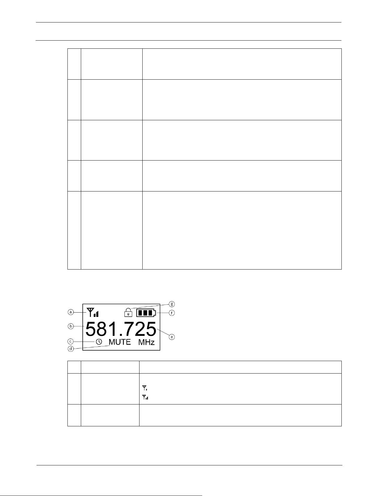
8.2 LCD display
ID
Item
Description, usage and notes
a RF power icon
The RF power indicator is always visible.
indicates RF power is set to low.
indicates RF power is set to high (band specific).
b
Frequency in
MHz
The portion of the tuned frequency to the left of the decimal in
millions when the transmitter home screen is set to Freq.
Loading ...
Loading ...
Loading ...