Loading ...
Loading ...
Loading ...

RE3
UHF Wireless RE3-HHT handheld tr ansmitter | en 41
Electro
-Voice Installation manual 2021.06 | 03 | F.01U.362.808
2
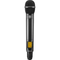
Transmitter
handle / battery
cover
This section provides a primary gripping and mounting area, and
serves as sliding cover for the battery compartment.
3 Control section
This section contains the LCD display, three menu navigation
buttons, power button, charging contacts, LED indicator, and the
sync port on opposite side of display.
4
Sliding menu
navigation button
cover
This sliding cover protects the menu navigation buttons. Sliding
the cover toward the LCD display reveals the buttons. Close the
cover by sliding it in the other direction protects the buttons.
5 LCD Display Backlit LCD displays all operating information and menus.
6
Battery
compartment
Holds two AA or AA-size rechargeable cells. Install AA cells
according to polarity orientation as shown.
7 Charging contact
Three charging contacts, one to the left of the power button and
two to the right are for use when using the optional BC2 battery
charger and rechargeable cells.
8 Power button
This is a multi-purpose button, functioning as a power on and off
switch, a transmitter mute switch, as well as a menu escape
switch.
To power ON transmitter: press for one second
To power OFF transmitter: press and hold until transmitter turns
off. PW OFF is displayed.
To MUTE transmitter: press briefly (less than one second). MUTE
appears on LCD.
To UNMUTE transmitter (when muted): press briefly (less than
one second). MUTE disappears on LCD display.
While in parameter edit mode, press to return to home screen.
CANCEL appears on the screen and no setting changes are
saved.
9 Charging contacts
Three charging contacts, one to the left of the power button and
two to the right are for use when using the optional BC2 battery
charger and rechargeable cells.
10 LED indicator
Indicates transmitter operating status as follows:
Glows solid green when transmitter is on.
Flashes green when transmitter is in mute mode.
Glows solid red when battery is low.
11
Transmitter tail
end
The lowermost surface in the display and control section.
Loading ...
Loading ...
Loading ...