Loading ...
Loading ...
Loading ...
24
en | RE3-RX r eceiver
RE3 UHF
Wireless
20
21.06 | 3 | F.01U.362.808 Installation manual Electro-
Voice
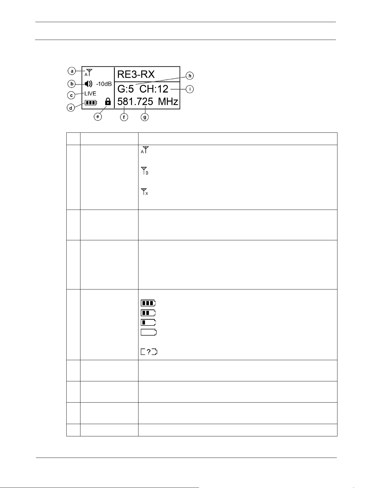
7.2 LCD display
ID
Item
Description, usage and notes
a
Antenna status
icon
indicates the diversity circuit is choosing antenna A signal at
the moment.
indicates the diversity circuit is choosing antenna B signal at
the moment.
indicates there is no antenna signal present for the diversity
circuit to choose.
b
Audio output
volume level
Displays the receiver audio output volume level. Menu item
adjustment allows settings between 0dB to -50dB in 1dB
increments. Beyond -50 is MUTE.
c
Transmitter
activity status
Displays the following possible transmitter audio states:
LIVE indicates mated transmitter audio is live and present at the
receiver.
MUTE indicates mated transmitter is in mute mode.
NoSYNC indicates no synced transmitter is on.
d
Mated transmitter
battery status
icon
Indicates the synced transmitter’s battery life.
= between 40% and 100% charge remains.
= between 20% and 39% charge remains.
= between 10% and 19% charge remains.
= below 10% charge remains. Low Battery begins flashing
on display.
= no battery info present.
e
KeyLock mode
icon
Indicates receiver KeyLock mode is on. Icon disappears from
display when off. See turning on and off KeyLock below.
f Frequency in MHz
The portion of the receiver’s tuned frequency to the left of the
decimal in millions.
g Frequency in kHz
The portion of the receiver’s tuned frequency to the right of the
decimal in thousands.
h
Group number
The group number of the receiver’s tuned frequency.
Loading ...
Loading ...
Loading ...