
Installation instructions
Environmental Monitoring Probe
EMPDT1H1C2
English
Eaton is a registered trademark of Eaton Corporation or its subsidiaries and
affiliates.
All other trademarks are properties of their respective companies.
©Copyright 2019 Eaton Corporation. All rights reserved.
No part of this document may be reproduced in any way without the express written
approval of Eaton Corporation.

1 Description and features
The optional Environmental Monitoring Probe (EMP) enables you to collect
temperature and humidity readings and monitor the environmental data
remotely.
You can also collect and retrieve the status of one or two dry contact devices
(not included).
Up to 3 Environmental Monitoring Probe can be daisy chained on one device.
You can monitor readings remotely using SNMP or a standard Web browser
through the Network module.
This provides greater power management control and flexible monitoring
options.
The EMP device is delivered with a screw and screw anchor, magnets, nylon
fasteners, tie wraps, and magnets. You can install the device anywhere on the
rack or on the wall near the rack.
The EMP has the following features:
• The hot-swap feature simplifies installation by enabling you to install the probe safely without
turning off power to the device or to the loads that are connected to it.
• The EMP monitors temperature and humidity information to help you protect critical equipment.
• The EMP measures temperatures from 0°C to 70°C with an accuracy of ±2°C.
• The EMP measures relative humidity from 10% to 90% with an accuracy of ±5%.
• The EMP can be located some distance away from the device with a CAT5 network cable up to
50m (165 ft) long.
• The EMP monitors the status of the two user-provided contact devices.
• Temperature, humidity, and contact closure status can be displayed through a Web
browserthrough the Network module or LCD interface (if available)
• A Temperature and Humidity Offset can be set.
EMPDT1H1C2 is compatible with G3, G3+ and High Density range of rack PDU
using a firmware version 4.x or later.
Latest firmware is available here: www.eaton.eu/RackPDUfirmware
For more information, refer to the device manual.

2 Unpacking the EMP
The sensor will include the following:
• EMPDT1H1C2 sensor
• Dry contact terminal block
• Quickstart
• USB to RS485 converter
• RJ45 female to female connector
• Wall mounting screw and anchor
• Rack mounting screw nut and washer
• Tie wraps (x2)
• Nylon fastener
Packing materials must be disposed of in compliance with all local
regulations concerning waste.
Recycling symbols are printed on the packing materials to facilitate sorting.
3 Installing the EMP
3.1 Defining EMPs address and termination
3.1.1 Manual addressing
Define different address for all the EMPs in the daisy-chain.
Set the RS485 termination (TER) to 1 on the last EMP of the daisy chain, set it to
0 on all the other EMPs.
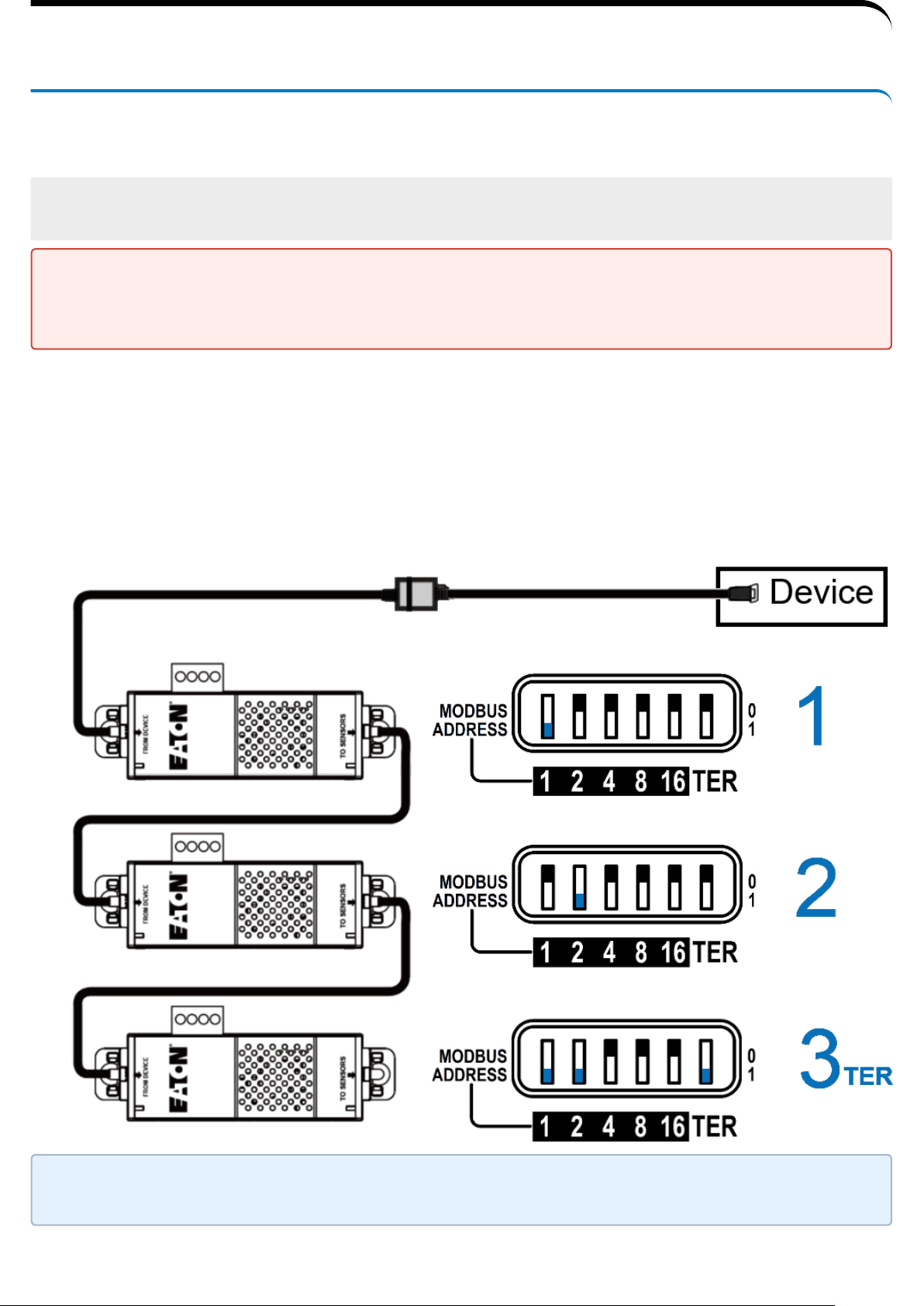
A- Example:manual addressing of 3 EMPs connected to
the Device
Address must be defined before the EMP power-up otherwise the changes
won't be taken into account.
Do not set Modbus address to 0,otherwise the EMP will not be detected.
Green LED of the TO DEVICE RJ45 connector shows if the EMP is powered by
the Network module.
3.2 Mounting the EMP
The EMP includes magnets, cable ties slots and keyholes to enable multiple
ways of mounting it on your installation.
Bottom mounting capabilities:
• magnets
• keyholes
• tie wraps
• nylon fastener
Side mounting
• magnets
• tie wraps
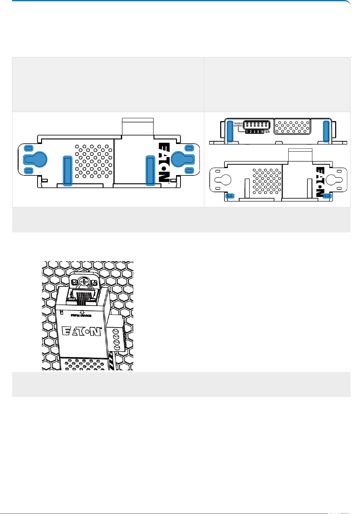
3.2.1 Rack mounting with keyhole example
To mount the EMP on the rack, use the supplied screw, washer and nut.
Then, mount the EMP on the screw and tighten it.
3.2.2 Rack mounting with tie wraps example
To mount the EMP on the door of the rack, use the supplied cable ties.
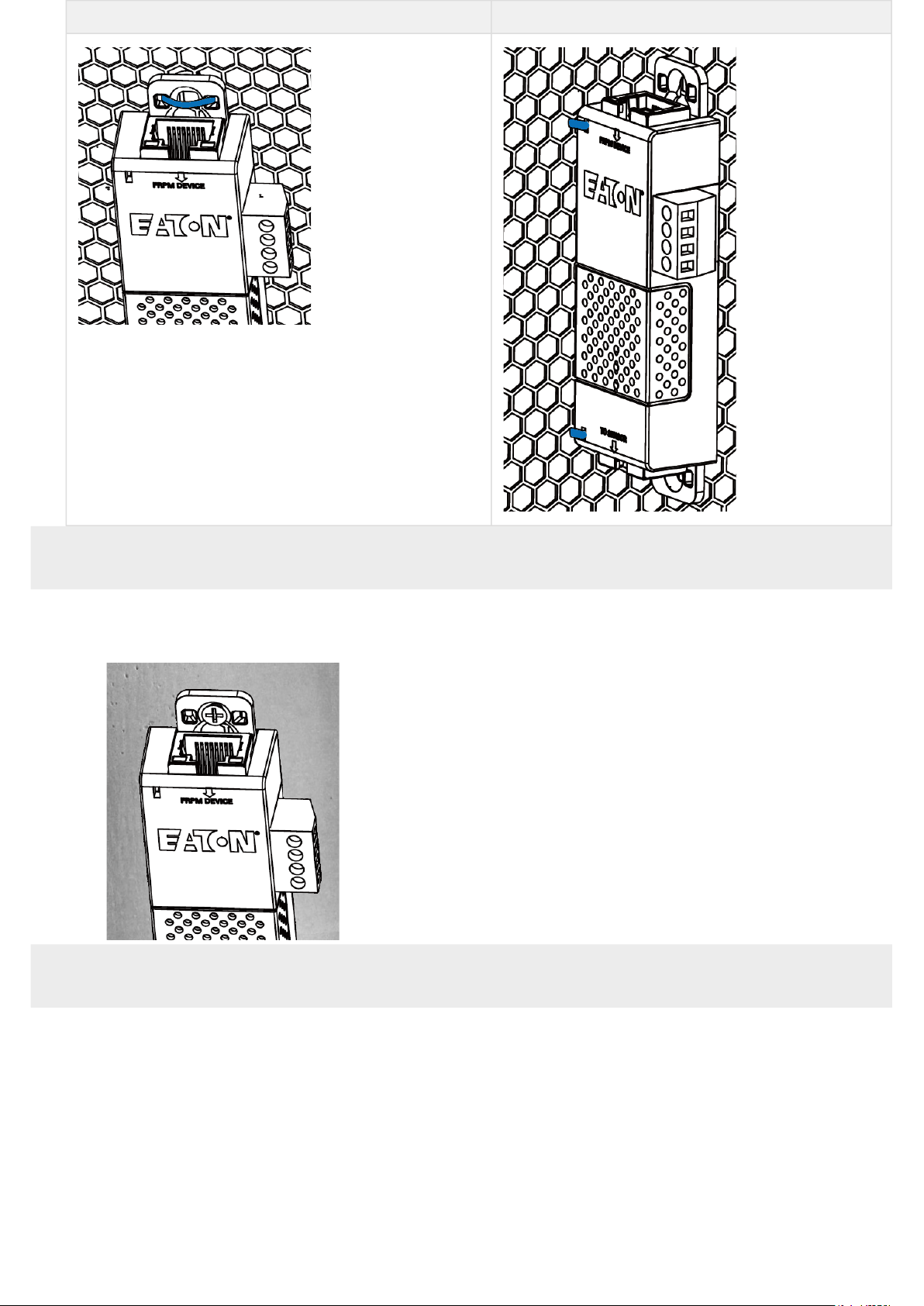
Bottom mounting Side mounting
3.2.3 Wall mounting with screws example
To mount the EMP on the wall close to the rack, use the supplied screw and
screw anchor. Then, mount the EMP on the screw and tighten it.
3.2.4 Wall mounting with nylon fastener example
To mount the EMP within the enclosure environment, attach one nylon
fastener to the EMP and the other nylon fastener to an enclosure rail post.
Then, press the two nylon strips together to secure the EMP to the rail post.
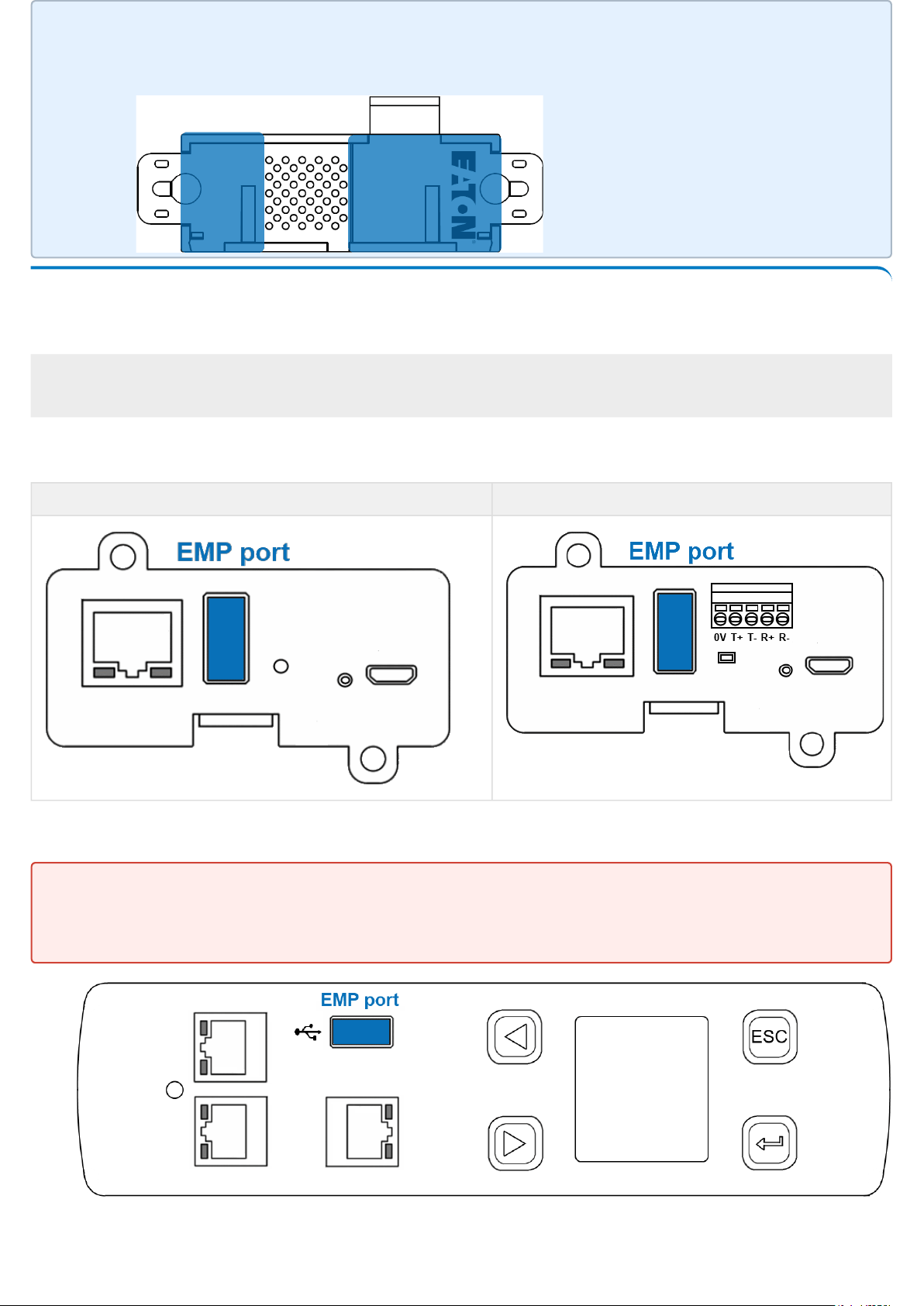
3.3 Cabling the first EMP to the device
3.3.1 Available Devices
A- Network-M2 and INDGW-M2
Network-M2 INDGW-M2
B- ePDU control module
Cut nylon fastener and stick it on the EMP bottom on the location
highlighted below, this will prevent to interfere with the EMP data
acquisition parts.
EMPDT1H1C2 must be connected to the ePDU USB port using the USB to
RS485 converter supplied on the box
The EMP001 and EMPDT1H1C2 can not be used on the same device
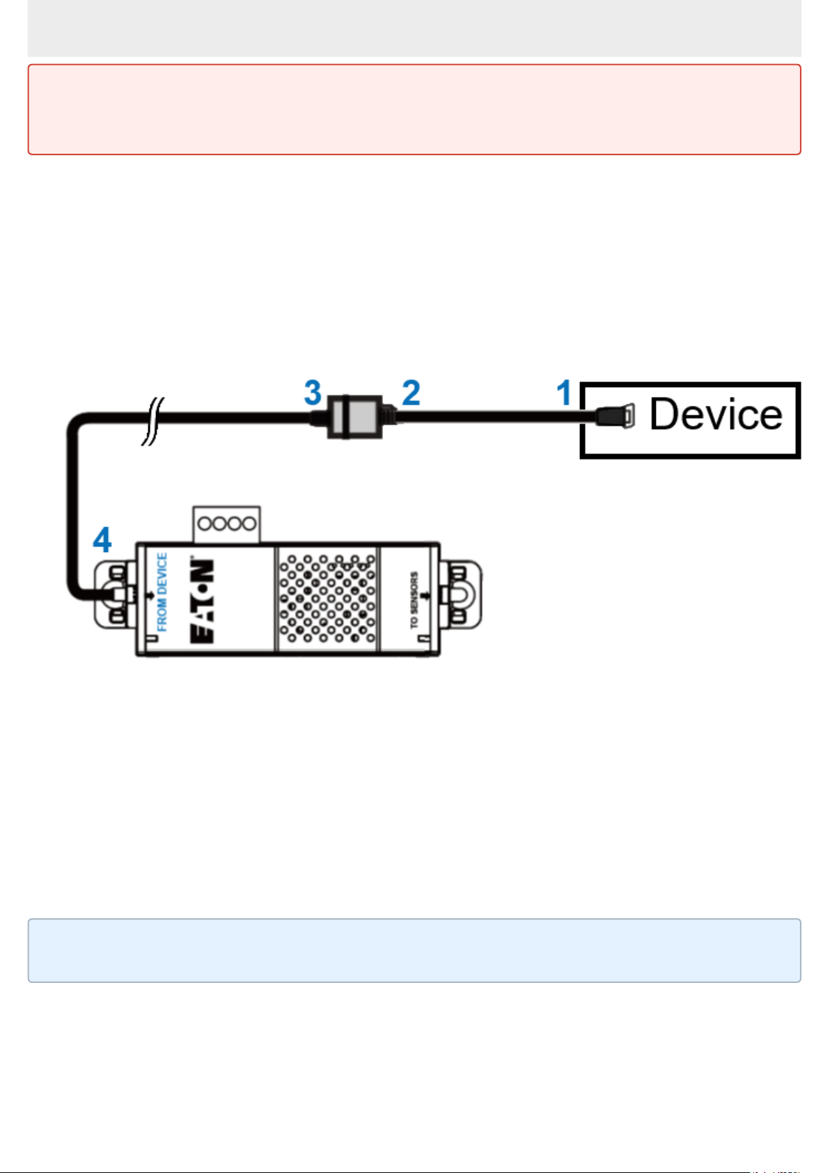
3.3.2 Connecting the EMP to the device
A- Material needed:
• EMP
• RJ45 female/female connector (supplied in EMP accessories)
• USB to RS485 converter cable(supplied in EMP accessories)
• Ethernet cable (not supplied).
• Device
B- Connection steps
Step 1 – Connect the "USB to RS485 converter cable" to the USB port of the
Device.
Step 2 – Connect the "USB to RS485 converter cable" to the RJ45 female/
female connector.
Step 3 –Connect the Ethernet cableto theother end of the RJ45 female/female
connector.
Step 4–Connect the other end of the Ethernet cable to the RJ-45 port on the
EMP (FROM DEVICE).
Address must be defined before the EMP power-up otherwise the changes
won't be taken into account.
Do not set Modbus address to 0,otherwise the EMP will not be detected.
Use the supplied tie wraps to secure the "RS485 to USB cable" to the Network
cable.
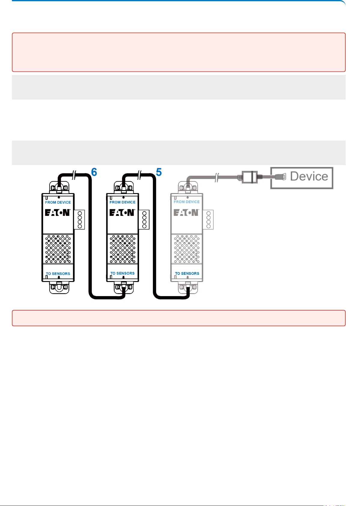
3.4 Daisy chaining EMPs
3.4.1 Material needed:
• First EMP connected to the device (refer to previous section)
• Additional EMPs
• 2 x Ethernet cable (not supplied).
• Device
3.4.2 Steps
STEP 5–Connect the Ethernet cable to the "TO SENSORS" port of the first EMP,
and to the "FROM DEVICE" port of the second EMP.
STEP 6–Connect the Ethernet cable to the "TO SENSORS" port of the second
EMP, and to the "FROM DEVICE" port of the third EMP.
Address must be defined before the EMP power-up otherwise the changes
won't be taken into account.
Do not set Modbus address to 0,otherwise the EMP will not be detected.
Up to 3 EMP can be daisy chained on one device.

3.5 Connecting an external contact device
To connect an external device to the EMP:
1- Connect the external contact closure inputs to the terminal block on the EMP
(see the table and the figure below):
• External contact device 1. Connect the return and signal input wires from device 1 to screw
terminals 1.
• External contact device 2. Connect the return and signal input wires from device 2 to screw
terminals 2.
2- Tighten the corresponding tightening screws on top of the EMP to secure the
wires.

4 Commissioning the EMP
4.1 On the Network-M2 device
STEP 1:Connect to the Network Module
• On a network computer, launch a supported web browser. The browser window appears.
• In the Address/Location field, enter:https://xxx.xxx.xxx.xxx/where xxx.xxx.xxx.xxx is the IP
address of the Network Module.
• The log in screen appears.
• Enter the user name in the User Name field.
• Enter the password in the Password field.
• ClickSign In. The Network Module web interface appears.
STEP 2:Navigate to Cards/Commissioningpage
STEP 3: Proceed to the commissioning (refer to the contextual help for
details: Cards>>>Commissioning (Sensors)
• Click Discover. The EMP connected to the Network module appears in the table.
• Press the pen logo to edit EMP information and access its settings.
• Click Define offsets to define temperature or humidity offsets if needed.
STEP 4: Define alarm configuration (refer to the contextual help for details:
Sensors>>>Alarm configuration)
• Click on the Sensors menu that has just appeared on the left bar after the EMP discovery.
• Select the Alarm configuration page.
• Enable or disable alarms.
• Define thresholds, hysteresis and severity of temperature, humidity and dry contacts alarms.
4.2 On the ePDU G3 device
Sensors must be discovered manuallyonce connected to theePDU.
3 ways tosetup the sensor to the ePDU: via the ePDULCD, via theWeb
Interfaceor viaCLI command.
When discovered, the orange LEDs of the EMP RJ45 connectors shows the
data traffic.
Before connecting the sensor to the Rack PDU make sure the firmware
version is 4.x or later .
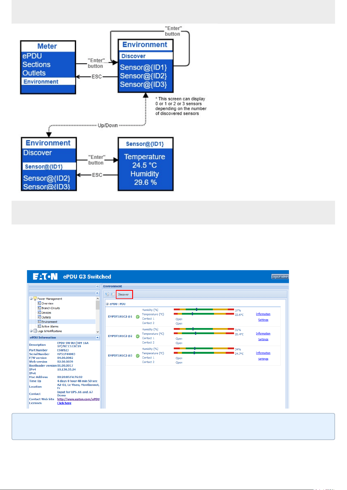
4.2.1 Discover the sensor via the LCD
4.2.2 Discover the sensor via the Web Interface
Connect to the Web pages with the ePDU IP address
In the "Environment" menu, click the "Discover" button
Discover button => Search for sensors =>X USB senosor(s) discovered
The Environment menu appears only when an EMP is connected to the Rack
PDU
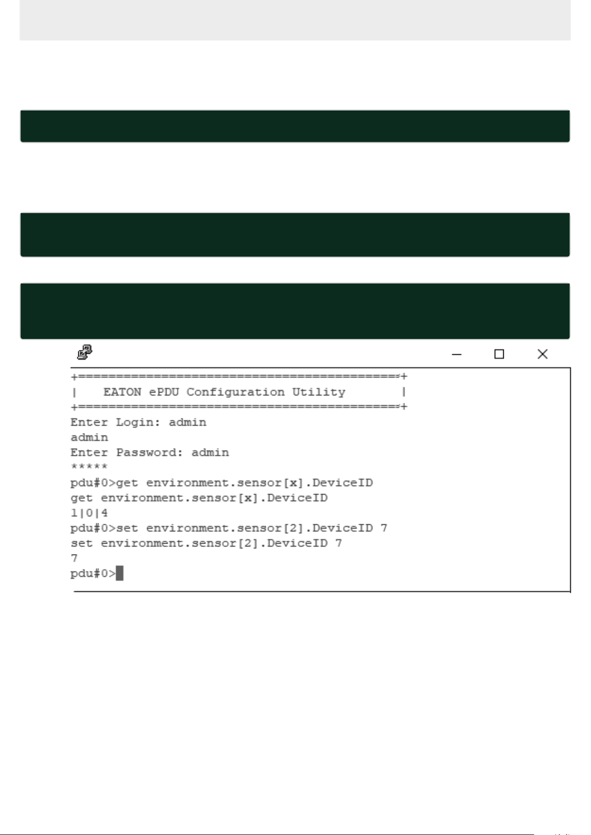
4.2.3 Discover the sensorusing CLI command
Use a tool as Putty and connect with the IP address in "Telnet", "SSH" or
"serial" mode
To check the availability place for the new sensor, use the command :
get environment.sensor[x].DeviceID
In this situation the position 2 is available for use the new sensor. (see
screenshot below)
To reset the SerialNumber, use the command line :
set environment.sensor[x].iSerialNumber {1 space only to be set}
- {x} is the position chosen previously.
To set the address, use the command line :
set environment.sensor[x].DeviceID {address}
- {address} is the address of the Usb sensor defined by the DIP switch.
- {x} is the position chosen previously.
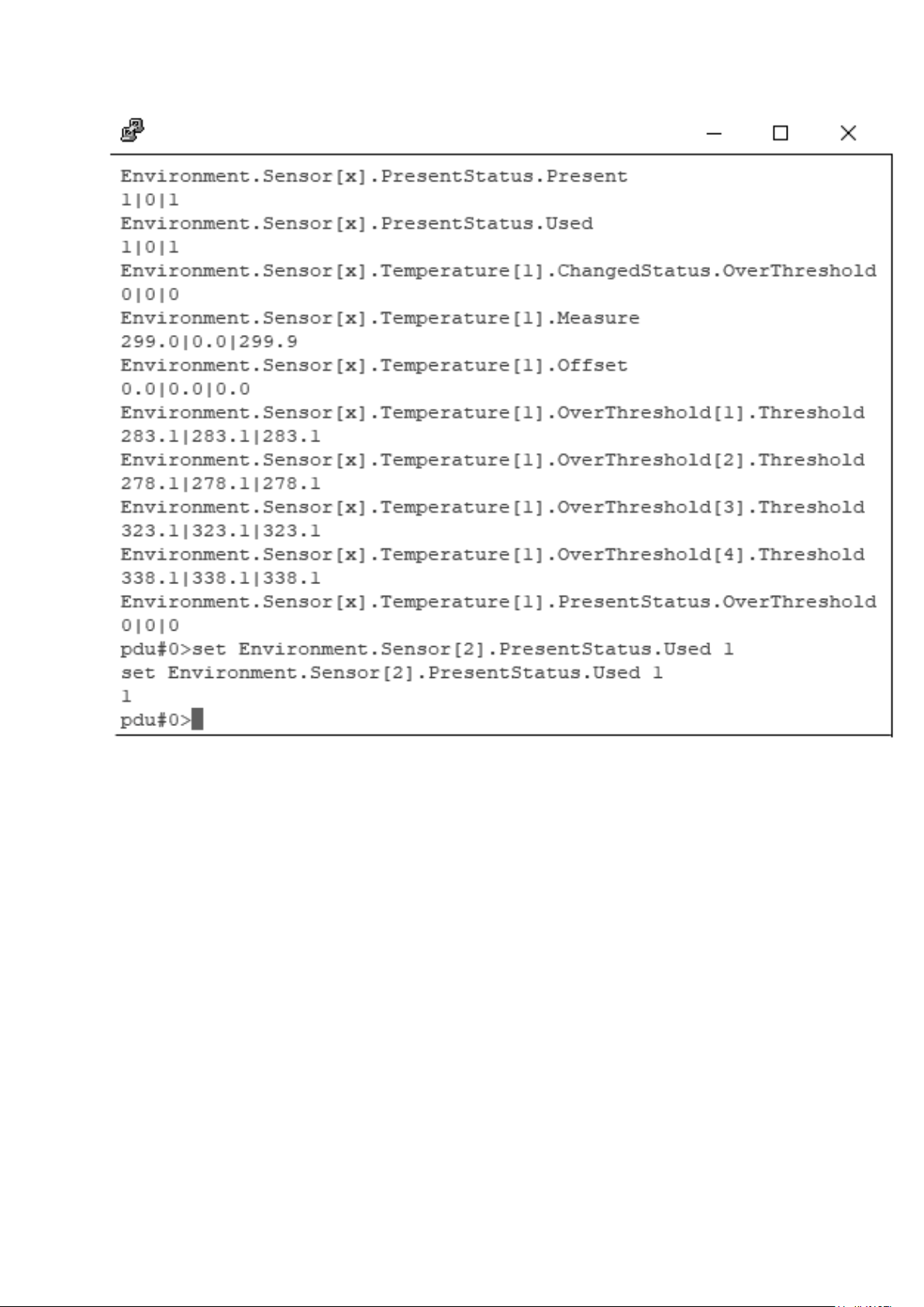
Valid this new sensor with the command line :
setEnvironment.Sensor[x].PresentStatus.Used 1
The new sensor appears in the Web page after 1min
