MS6505
HUMIDITY TEMPERATURE METER
INSTRUCTION MANUAL
HUMIDITY TEMPERATURE METER
INSTRUCTION MANUAL

HUMIDITY TEMPERATURE METER
INSTRUCTION MANUAL
CONTENTS
CONTENTS
TITLE
PAGE
1.
SAFETY INFORMATION
………………………………………1
1.1
PRELIMINARY
………………………………………1
1.2
DURING USE
………………………………………1
1.3
SYMBOLS
………………………………………2
1.4
MAINTENANCE
………………………………………2
2.
DESCRIPTION
………………………………………3
2.1
NAMES OF COMPONENTS
………………………………………3
2.2
SYMBOL DEFINITION
………………………………………4
2.3
BUTTONS ELUCIDATION
………………………………………5
3.
SPECIFICATIONS
………………………………………7
3.1
GENERAL SPECIFICATIONS
………………………………………7
3.2
ELECTRICAL SPECIFICATIONS
………………………………………8
4.
OPERATING INSTRUCTION
………………………………………10
4.1
POWER-UP
………………………………………10
4.2
MEMORY SPARE SPACE
………………………………………10
4.3
HUMIDITY MEASUREMENT
………………………………………10
4.4
TEMPERATURE MEASUREMENT
………………………………………11
4.5
SELECTING THE TEMPERATURE SCALE
………………………………………11
4.6
MAX/MIN OPERATION
………………………………………11

HUMIDITY TEMPERATURE METER
INSTRUCTION MANUAL
CONTENTS
4.7
DATA HOLD
………………………………………12
4.8
TIME OPERATION
………………………………………12
4.9
CLOCK SETUP
………………………………………13
4.10
RECORDING INTERVAL SETUP
………………………………………13
4.11
DATALOGGER
………………………………………14
4.12
BACK LIGHT
………………………………………14
4.13
AUTO POWER OFF
………………………………………15
4.14
DIGITAL OUTPUT
………………………………………15
4.15
9V BATTERY REPLACEMENT
………………………………………15
4.16
3V BATTERY REPLACEMENT
………………………………………16
4.17
USE THE TRIPOD CONNECTOR
………………………………………16
5.
ENCLOSED SOFTWARE PCLINK
………………………………………17
5.1
ILLUMINATION FOR INSTALLATION
………………………………………17
5.2
INSTALLATION OF PCLINK
………………………………………17
5.3
EXECUTION OF PCLINK
………………………………………18
5.4
REALTIME DATA GRAPH WINDOW AND REALTIME TABLE WINDOW
………………………………………19
5.5
DATA DOWNLOAD
………………………………………19
6.
ACCESSORIES
………………………………………20
6.1
SUPPLIED WITH THE MULTIMETER
………………………………………20
6.2
OPTIONAL ACCESSORIES
………………………………………20

HUMIDITY TEMPERATURE METER
INSTRUCTION MANUAL
SAFETY INFORMATION
1. SAFETY INFORMATION
Read the following safety information carefully before attempting to operate or service the meter. Use the meter only as
specified in this manual, otherwise, the protection provided by the meter may be impaired.
With proper use and care, your digital meter will provide you satisfactory service for years.
1.1 PRELIMINARY
1.1.1 When the meter is delivered, check that it has not been damaged in transit.
1.1.2 When poor condition under harsh preservation or shipping conditions caused, inspect and confirm this meter without
delay.
1.2 DURING USE
1.2.1 Operate the meter under the condition of stated temperature and humidity.
1.2.2 If any faults or abnormalities are observed, the meter can not be used any more and it has to be checked out.
1.2.3 Please do not store or use meter in areas exposed to direct sunlight, high temperature, humidity or condensation.
1.2.4 Don't touch or manipulate the sensor.
1.2.5 Don't expose the sensor to direct light, this causes a false reading.
1.2.6 Don't expose the sensor to static electricity.
1.2.7 Never dip the sensor directly in the water or impregnant.
- 1 -

HUMIDITY TEMPERATURE METER
INSTRUCTION MANUAL
SAFETY INFORMATION
1.3 SYMBOLS
Comply with EMC
Important safety information, refer to the operating manual.
1.4 MAINTENANCE
1.4.1 Repairs or servicing not covered in this manual should only be performed by qualified personnel.
1.4.2 If it exists dust on the sensor, use clean air to blow it away or use alcohol to scrub it away lightly. Do not use other
chemical impregnant for scrubbing.
1.4.3 Do not use abrasives or solvents on the meter, use a damp cloth and mild detergent only.
1.4.4 Always set the power switch to the OFF position when the meter is not in use.
1.4.5 If the meter is to be stored for a long period of time, the batteries should be removed to prevent damage to the unit.
- 2 -

HUMIDITY TEMPERATURE METER
INSTRUCTION MANUAL
DESCRIPTION
2. DESCRIPTION
- This meter is a digital Humidity/Temperature meter for use a polymer capacitive and semiconductor sensor.
- This meter is a portable professional measuring instrument with large LCD and back light for easily reading.
- This meter can be connected with the computer for large recording of measuring data, analysis and printing, etc.
-This meter has the memory function, can save 16300 groups of measuring data for 24 times.
-This meter has clock function, can display the minute, hour, date, month and year.
- This meter has function of data hold.
- This meter has function for measurement of MAX/MIN value.
- When using, it can show the temperature and the humidity.
- This meter has function of auto power off.
- Low battery indication are provided.
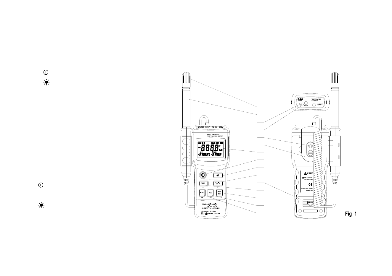
2.1 NAMES OF COMPONENTS
⑴ Dust mask
⑵ Sensor probe
⑶ AC power adapter connector
⑷ RS-232 Digital output connector
⑸ Tripod connector
⑹ Hang Ring
- 3 -
HUMIDITY TEMPERATURE METER
INSTRUCTION MANUAL
DESCRIPTION
⑺ LCD display
⑻ “ “→ON/OFF button
⑼ “ “→Back light button
⑽ “℃/℉“→Centigrade and Fahrenheit
transformingbutton
⑾ Battery cabinet cover
⑿ “REC“→control button
⒀ “MAX/MIN“→MAX, MIN function control button
⒁ “TIMER”→Timer display button
⒂ “HOLD“→HOLD button
2.2 BUTTONS ELUCIDATION
• Button
This Button is used to the switch of power.
• Button
This button is used to the switch of back light.
• ℃/℉ Button
This button is used to transform ℃ or ℉ range.
- 4 -
(1)
(2)
(3)
(4)
(5)
(6)
(7)
(8)
(9)
(10)
(11)
(12)
(13)
(14)
(15)

HUMIDITY TEMPERATURE METER
INSTRUCTION MANUAL
DESCRIPTION
• REC Button
This button is used to select the memory switch.
• HOLD Button
This Button is used to the data hold switch.
• TIMER Button
This Button is used to select the clock switch.
• MAX/MIN Button
This Button is used to the switch of maximum value and minimum value measure.
2.3 SYMBOL DEFINITION
℃ Centigrade indication.
℉ Fahrenheit indication.
%RH Relative Humidity indication.
MAX The Maximum value is displayed.
MIN The Minimum value is displayed.
This indicates auto power off is enabled.
REC This indicates that the display data is being saved.
This indicates that the display data is being held.
- 5 -

HUMIDITY TEMPERATURE METER
INSTRUCTION MANUAL
DESCRIPTION
y year
m-d month - day
h:m hour - minute
m:s minute - second
The battery is not sufficient for proper operation.
- 6 -

HUMIDITY TEMPERATURE METER
INSTRUCTION MANUAL
SPECIFICATIONS
3. SPECIFICATIONS
Accuracy is specified for a period of year after calibration and at 18℃ to 28℃(64℉ to 82℉) with relative humidity to 75%.
3.1 GENERAL SPECIFICATIONS
3.1.1 Numerical Display: 4 digital Liquid Crystal Display.
3.1.2 Measurement Range: Humidity→0%~100%RH, Temperature→ -20℃~ +60℃, -4℉~ +140℉
3.1.3 Resolution: Humidity→ 0.1%RH, Temperature→ 0.1℃, 0.1℉
3.1.4 Accuracy: Humidity→±2.5%RH at 25℃, Temperature→± 0.7℃, ±1.4℉
3.1.5 Temperature modulus: When operating temp. is out of the range of 18℃~28℃, you should add the following non-accuracy
into the indicated temp.: indicating value×0.01%±0.03℃; indication value×0.01%±0.06℉.
3.1.6 Measuring method: Dual-slope integration A/D converter
3.1.7 Response Time: Humidity→ 75 sec. In slowly moving air, Temperature→ 40 sec. in slowly moving air
3.1.8 Signal Output: RS-232 Data Output
3.1.9 Operating Environment: Humidity→ 0 to 80%RH (non-condensing).
Temperature→ 0℃~40℃, 32℉~122℉ (non-condensing).
Altitude up→ to 2000 meters.
3.1.10 Storage Environment: Humidity→ 0 to 85%RH (non-condensing)
Temperature→ -10℃~50℃, 14℉~140℉ (non-condensing)
3.1.11 Power Requirements: Battery→ One 9V battery 006p or IEC 6F22 or NEDA1604
AC adapter→ 9VDC /30mA minimum Plug Diameter: Ø 3.5 mm x 1.35mm
- 7 -

HUMIDITY TEMPERATURE METER
INSTRUCTION MANUAL
SPECIFICATIONS
3.1.12 Low Battery Indication: ‘ ’ displayed
3.1.13 Dimension: Meter→ 183(L)x 74(W)x 33(H)mm; 7.2(L)× 2.9(W)x 1.3(H)inch
Sensor Probe→ 208(L)x 15(D)mm; 8.2(L)x 0.6(D)inch
3.1.14 Weight: Approx.330g
3.2 ELECTRICAL SPECIFICATIONS
Circumstance Temperature: 235℃, Relative Humidity: < 75%
3.2.1 Humidity sensor
HIH-3610(Honeywell)
- 8 -

HUMIDITY TEMPERATURE METER
INSTRUCTION MANUAL
SPECIFICATIONS
3.2.2 Temperature sensor
LM335Z(National Semiconductor Corporation)
Test Conditions
Parameter
Operating Output Voltage
TC=25℃, IR=1mA
2.98V
Output Voltage Temperature Coefficient
10mV/℃
3.2.3 Humidity
Range
Resolution
Accuracy
0 ~ 100%RH
0.1 %RH
± 2.5%RH at 25℃
3.2.4 Temperature
Range
Resolution
Accuracy
-20℃ ~ +60℃
0.1 ℃
± 0.7℃
-4℉ ~ +140℉
0.1 ℉
± 1.4℉
- 9 -

HUMIDITY TEMPERATURE METER
INSTRUCTION MANUAL
OPERATING INSTRUCTION
4. OPERATING INSTRUCTION
4.1 POWER-UP
Press the “ ” button to turn the Humidity Temperature Meter ON or OFF.
4.2 MEMORY SURPLUS SPACE
When the meter is power-on, the LCD will show the surplus space of the memory
in the middle and the below. The value in the middle stands for of the data which
can be recorded in the memory remaining space. Each recorded data may have
many groups of data.
The value in the below stands for the group of the data which can be recorded in
the memory remaining space. See the Fig. 2, It indicates that there are 16300
records memory space available.
4.3 HUMIDITY MEASUREMENT
For measurement, place the sensor probe in the tested environment.
NOTE:
1. Measurement Range: 0%~100%RH
2. Operating Environment: Relative humidity: 0 to 80%RH, Temperature: 0℃~40℃, 32℉~104℉ (without dew).
- 10 -

HUMIDITY TEMPERATURE METER
INSTRUCTION MANUAL
OPERATING INSTRUCTION
4.4 TEMPERATURE MEASUREMENT
For measurement, place the sensor probe in the tested environment.
NOTE:
1. Measurement Range: -20℃~ +60℃,-4℉~ +140℉。
2. Operating Environment: Relative humidity: 0 to 80%RH, Temperature: 0℃~40℃, 32℉~104℉ (without dew).
4.5 SELECTING THE TEMPERATURE SCALE
When the meter is power-on, the scale setting is auto set at Celsius℃ scale. The user may change it to Fahrenheit ℉ by
pressing “℃/℉” button and revert to Celsius by pressing “℃/℉” button again.
NOTE:
When the meter is under "MAX MIN" operation, "℃/℉" button is disabled. (when you press "℃/℉" button in "MAX/MIN" mode,
there will be two continuous beeps.)
4.6 MAX/MIN MEASUREMENT:
4.6.1 When one press the "MAX/MIN" button the meter will enter the MAXIMIN mode. Under this mode the maximum value,
minimum value is kept in the memory simultaneously and updated with every new data. When the MAX symbol is display,
the Maximum is shown on the display.
4.6.2 Press "MAX/MIN" again, then the MIN symbol is on the display and also the minimum reading.
- 11 -

HUMIDITY TEMPERATURE METER
INSTRUCTION MANUAL
OPERATING INSTRUCTION
4.6.3 Press "MAX/MIN" again, MAX, and MIN will blink together. This means that all these data is updated in the memory and
the reading is the present temperature and humidity.
4.6.4 Press "MAX/MIN" again, MAX will go back. One may press "MAX/MIN" to circulate the display mode among these
options.
4.6.5 To exit the MAX/MIN mode, one may press and hold "MAX/MIN" for 2 seconds.
NOTE:
When the meter is under "MAX/MIN" operation, "℃/℉" button is disabled. (when you press "℃/℉" button in "MAX/MIN" mode,
there will be two continuous beeps.)
4.7 READ HOLD
The user may hold the present reading and keep it on the display by pressing the "HOLD" button. When the held data is no
longer needed, one may release the data-hold operation by pressing "HOLD" button again.
NOTE:
When the meter is under Data Hold operation, the "MAX/MIN" and "℃/℉" button are disabled. (when you press "℃/℉" and
"MAX/MIN" button in HOLD mode, there will be two continuous beeps.)
4.8 TIME OPERATION
When the “TIME” button is pressed, the LCD will display time, it will show year in the middle of the LCD, show month and day on
the left bottom of the LCD, show hour and minute on the right bottom of the LCD.
Press any button except the “TIME” button will exit from this mode, and the data display mode is reverted.
- 12 -
HUMIDITY TEMPERATURE METER
INSTRUCTION MANUAL
OPERATING INSTRUCTION
NOTE:
1. After the meter is power-on, if the time is displayed 2000/0I/01 00:00, which
means the battery should be replaced. Remove the rear case, put in a new 3V
button cell.
2. Pressing “TIME” button will not interrupt the recording and “MAX/MIN” measuring
operation.
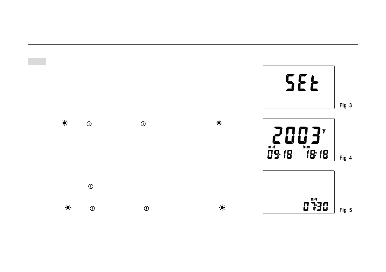
4.9 CLOCK SETUP
4.9.1 Press “ ” and “ ” button , release “ ” firstly and then release“ ”
button till “SET” displays on LCD, which will lead to SETUP mode ( see Fig.3).
4.9.2 Press “TIME” (CLOCK) button enter into time setup mode (see Fig.4 ).
4.9.3 Press “REC” or “℃/℉” to increase or decrease number. If press the
button for a while, the number will be increased or decreased quickly. Press
“TIME” (CLOCK) for adjusting, the order is yearmonthdayhour
minutesecond. then press “TIME” (CLOCK) to save the setting value. In
the course of setting up, If you want to exit from this mode and do not save
any value, press “ ” button to end.
4.10 RECORDING INTERVAL SETUP
4.10.1 Press “ ” and “ ” button , release “ ” firstly and then release“ ”
button till “SET” displays on LCD, which will lead to SETUP mode ( see Fig.3).
4.10.2 Press “℃/℉” (INTV) button to enter recording interval SETUP mode (see Fig.5).
4.10.3 Press “REC” or “℃/℉” to increase or decrease number. If press the
button for a while, the number will be increased or decreased quickly.
- 13 -

HUMIDITY TEMPERATURE METER
INSTRUCTION MANUAL
OPERATING INSTRUCTION
Press “HOLD” (INTV) for adjusting the next item, then press “HOLD” (INTV) to save the setting value. In the course of
setting up, If you want to exit from this mode and do not save any value, press “ ” button to end.
NOTE:
The time interval mode is minute and second.
4.11 DATA RECORDING
Press “REC” button, the meter will start recording according to the set time interval. After a set time interval will have a group of
data. At the beginning, REC will be shown on the left side of the LCD; press the “REC” button again will make the recording stop.
A whole data recording is finished.
When the memory is full, REC will be flashed per a second. If user wants to
check the memory content, should use RS-232 connecting line and the software
to send the content to the computer.
If you want to clear the memory, power off the meter, then press and hold “REC”
button and then press “ ” button and hold at least 2 seconds till CLR is shown
on LCD (see Fig. 6), which indicates that the memory is being cleared and finished
clearing till CLR dispears.
4.12 BACK LIGHT
If the light is dark to make the reading difficult when measuring, you can press “ ” button to open the back light which will last
for 15 sec.. You can close it up at any time once press “ ” button again.
- 14 -

HUMIDITY TEMPERATURE METER
INSTRUCTION MANUAL
OPERATING INSTRUCTION
NOTE:
• LED is the main source of back light. Its working current is large, often use back light will shorten the battery life, you’d better
not to use the back light so frequently unless it’s necessary.
• When the battery voltage is less than 7V, it will show “ ”. But if you use back light at the same time, maybe “ ” will
come up even if the battery voltage is more than 7V, because the working current is higher and the voltage will decline.
(When “ “ shows, the accuracy of the measurement can not be assured.) You need not replace the battery. When you
use normally (back light is not using), “ ” will not show up. You need replace it till “ ”show again.
4.13 AUTO POWER OFF:
When the meter is power-on, there will be shown on the left side of the LCD, which means the meter will be power-off after
30 minutes if no key operation and no RS232 communication and no recording.
One may press and hold "HOLD" button and then power on the meter. There will be two successive beeps to indicate that auto
power off is disabled and the will not be shown up.
4.14 DIGITAL OUTPUT:
The Digital Output is a 9600bps N 81 serial interface.
4.15 9V BATTERY REPLACEMENT
4.15.1 If the sign‘ ’appears on the LCD display, it indicates that the 9V battery should be replaced.
- 15 -

HUMIDITY TEMPERATURE METER
INSTRUCTION MANUAL
OPERATING INSTRUCTION
4.15.2 Turn the unit off. Remove the battery cover.
4.15.3 Replace the exhausted battery with a new one.
4.15.4 Put the battery cover as its origin.
4.16 3V BATTERY REPLACEMENT
4.16.1 When the meter is power-on, the time is always 2000/0I/01 00:00 which indicates that the battery should be replaced
with a new one.
4.16.2 Turn the unit off. Remove the battery cover and tripod connector.
4.16.3 Open up the battery cover.
4.16.4 Replace the exhausted battery with a new one.
4.16.5 Put the battery cover to its original place.
4.17 USE THE TRIPOD CONNECTOR
4.17.1 If needed, the meter can be fixed on the tripod.
4.17.2 The meter also can be hanged up for use.
- 16 -

HUMIDITY TEMPERATURE METER
INSTRUCTION MANUAL
PCLink (ENCLOSED SOFTWARE)
5. PCLink (ENCLOSED SOFTWARE)
5.1 ILLUMINATION FOR INSTALLATION
Connect software PCLink to your PC, then connect its interface to the meter for use.
• Minimum Hardware Requirements
486-100MHz minimum or equivalent PC,16MB memory, 5MB hard disk space minimum.
• Operating System Requirements
Win95/Win98/NT4.0 or later 32 bit operating system.
5.2 INSTALLATION OF PCLINK
Insert the SETUP floppy disk into computer. Select Run from the TaskBar Start menu. type “a:PCLink.exe” ,then press enter key,
and follow the prompts. Click “PCLink” program in program group from TaskBar start menu to run the program, refer to HELP for
detailed instruction.
- 17 -
HUMIDITY TEMPERATURE METER
INSTRUCTION MANUAL
PCLink (ENCLOSED SOFTWARE)
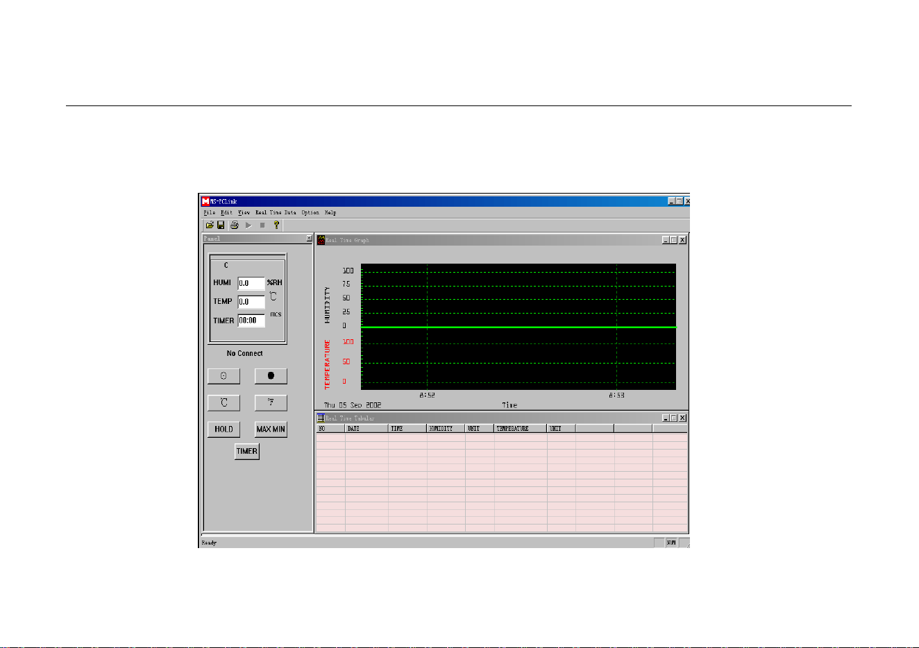
5.3 RUN PCLINK
Click “PCLink” program in program group from TaskBar start menu to run the “PCLink” program. (Fig 7)
MENU and
TOOLBAR→
←Realtime Data
Graph Window
Both-Way
Control Window→
←Realtime Data
Table Window
Fig. 7
- 18 -

HUMIDITY TEMPERATURE METER
INSTRUCTION MANUAL
PCLink (ENCLOSED SOFTWARE)
5.4 REALTIME DATA GRAPH WINDOW AND REALTIME TABLE WINDOW
5.4.1 Use the enclosed interface line connect with the PC.
5.4.2 Open PCLInk”
5.4.3 Click , then PCLink will collect data of the meter on graph window and table window in realtime sampling rate time. You
can input new sampling rate value on sampling rate edit label.
5.5 DATA LOAD
5.5.1 Use the enclosed interface line connect with the PC
5.5.2 Open PCLInk”
5.5.3 Click the DATALOGGER on the menu, and then PCLink will load the data of the meter to your PC. It will be indicated on
the PC as the list form.
Refer to instruction for other operation on our Web. (HELP on MENU)
- 19 -

HUMIDITY TEMPERATURE METER
INSTRUCTION MANUAL
ACCESSORIES
6. ACCESSORIES
6.1 SUPPLIED WITH THE MULTIMETER
⑴
Battery: 9V, NEDA 1604 or 6F22
9V,NEDA 1604、6F22
One piece
⑵
Battery: 3V, CR2032
3V,CE2032
One piece
⑶
Sensor Probe Holder
One piece
⑷
Carrying bag
One piece
⑸
Instruction Manual
One piece
6.2 OPTIONAL ACCESSORIES
⑴
PCLink
3.5” Floppy Disk
One piece
⑵
Interface line
One piece
⑶
AC adapter
9VDC/100mA
One piece
- 20 -

HYS005100 A0