1
14
14
15
15
16
18
16
14
14
20
15
16
17
10
19
2
11
11
21
12
3
4
5
6
7
8
9
13
13
OWNER'S MANUAL
WARNING: READ, UNDERSTAND AND FOLLOW ALL INSTRUCTIONS AND
WARNINGS BEFORE OPERATING THIS TOOL. FAILURE TO DO SO MAY
RESULT IN PERSONAL INJURY AND/OR PROPERTY DAMAGE AND WILL
VOID WARRANTY.
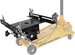
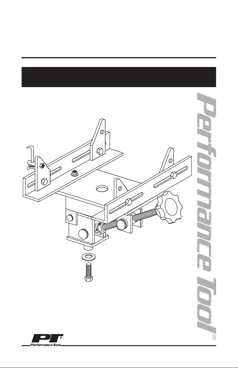
TRANSMISSION ADAPTER
300 LB. CAPACITY
Item Number W41044

WARNING!
Failure to read, understand and follow these warnings may result in loss of load, damage
to unit, and/or failure of unit resulting in personal injury or property damage.
WARNING!
Use this transmission adaptor only for the removal and installation of passenger car and light
duty truck transmissions. Do not overload beyond 300 lbs. Do not remove or install transmissions
with transfer cases attached.
Jack must be in fully lowered position to move load.
Always secure transmission in place with safety chains.
Use only with heavy frame service jack with a removable saddle.
Read, understand and follow all warnings listed in jack instruction manual.
Vehicle must be properly supported before starting repair. Refer to vehicle owner’s manual for
proper jacking procedures.
This unit is designed for use only on hard level surfaces capable of sustaining the load. Use of
unit on other than hard level surfaces can result in instability and possible loss of load.
IMPORTANT SAFETY INFORMATION
This instruction manual is intended for your benefit. Please read and follow the safety, assembly and maintenance steps described
within to ensure your safety and satisfaction. The contents of this instruction manual are based upon the latest product information
available at the time of publication. The manufacturer reserves the right to make product changes at any time without notice.
SAFETY GUIDELINES / DEFINITIONS
UNPACKING AND INSPECTION
WARNING: Read and understand this entire instruction manual before attempting to assemble, install, operate or maintain
this product. Failure to comply with the instructions may result in serious personal injury and/or property damage!
The following signal words are used to emphasize safety warnings that must be followed when using this product:
DANGER:
Indicates an imminently hazardous situation
that, if not avoided, WILL result in death or serious injury.
WARNING:
Indicates a potentially hazardous situation that,
if not avoided, COULD result in death or serious injury.
CAUTION:
Indicates a potentially hazardous situation that,
if not avoided, MAY result in minor or moderate injury.
NOTE: Indicates important information, which if not
followed, MAY cause damage to equipment.
After opening the packaging, unpack your new product and related parts and accessories. Please
inspect everything carefully for any damage that may have occurred during transit. Please check it
against the expanded parts list. If any parts are missing, please call customer service at 1-800-
426-1262 between 6 a.m. and 5 p.m. Pacific time.
WARNING: DO NOT operate this product if damaged during shipment, handling or misuse.
Do not operate the product until the parts have been replaced or the fault rectified. Failure to do
so may result in serious personal injury or property damage. All damaged parts must be repaired
or replaced as needed prior to operating this product. Check to see that all nuts, bolts and fit-
tings are secure before putting this product into service.
If you have any questions, or require assistance with damaged or missing parts, please contact
our customer service department at 1-800-426-1262. Please have the serial number, model
number, and date of purchase available for reference when calling.
WARNING. READ, UNDERSTAND AND FOLLOW ALL INSTRUCTIONS AND
WARNINGS BEFORE OPERATING THIS PRODUCT. FAILURE TO DO SO MAY RESULT
IN PERSONAL INJURY AND/OR PROPERTY DAMAGE AND WILL VOID WARRANTY.
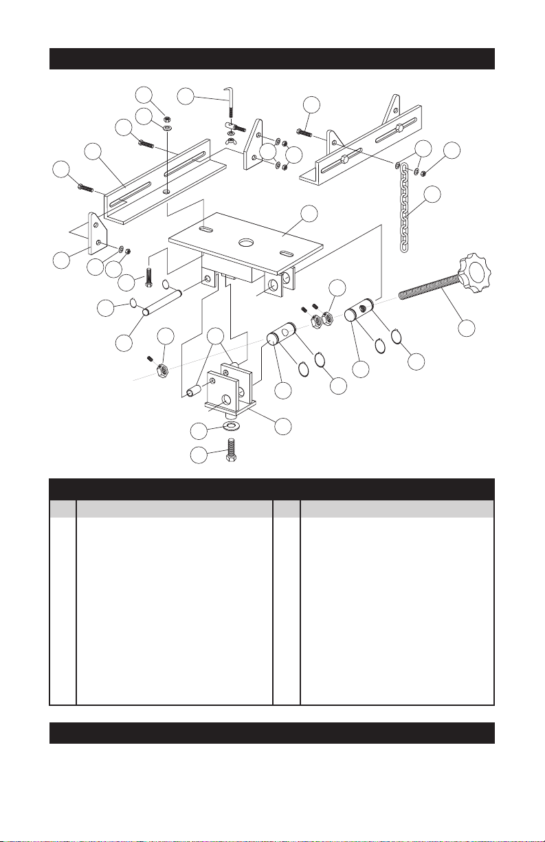
ASSEMBLY DIAGRAM
1
14
14
15
15
16
18
16
14
14
20
15
16
17
10
19
2
11
11
21
12
3
4
5
6
7
8
9
13
13
1. Install Threaded Bushing (3), into holes in Platform (1) using Large Snap Rings (11).
2. Screw Adjustable Tilt Knob (2) through threaded bushing approximately half way.
3. Install 2 Lock Nuts (13) approximately 3 in. from end of threaded shaft.
4. Install Non-Threaded Bushing (4) into holes in Pivot Frame (5) using Large Snap Rings (11).
5. Slide Non-Threaded Bushing over onto threaded shaft and install remaining Lock Nut (13).
ASSEMBLY INSTRUCTIONS
1 Platform .............................. 1
2 Adjustable Tilt Knob ........... 1
3 Threaded Bushing ............... 1
4 Non-Threaded Bushing ....... 1
5 Pivot Frame ......................... 1
6 Pivot Pin .............................. 1
7 Mounting Bracket Frame .... 2
8 Mounting Bracket ............... 4
9 Chain Hook Assembly ........ 1
10 Safety Chain ....................... 2
11 Large Snap Ring ................. 4
12 Small Snap Ring ................ 2
13 Lock Nut with Set Screw ... 3
14 M10 x 25 Bolt .................... 7
15 M10 Washer ....................... 7
16 M10 Nut ............................. 7
17 M8 x 25 Bolt ...................... 1
18 M8 Washer ......................... 2
19 M8 Nut ............................... 1
20 Large Retaining Washer ..... 1
21 Spacer ............................... 2
No. Description Qty. No. Description Qty.
EXPANDED PARTS LIST
LIMITED WARRANTY
PERFORMANCE TOOL® extends only the following warranties, and only to original retail purchasers. These
warranties give specific legal rights. Except where prohibited by local law, the law of the State of Washington
governs all warranties and all exclusions and limitations of warranties and remedies. There may be other rights
which vary from state to state.
PERFORMANCE TOOL® warrants the product to be free from defects in materials and workmanship under normal
use and service. A defective product may be returned for a free replacement within 90 days from the date of
purchase, provided that product is returned to place of purchase immediately after discovery of defect. After 90
days and up to one year from date of purchase, PERFORMANCE TOOL® will replace at no charge any parts which
our examination shall disclose to be defective and under warranty. These warranties shall be valid only when a sales
receipt showing the date of purchase accompanies the defective product or defective part (s) being returned. For
part (s) after 90 days, please remit your request, postage prepaid to:
PERFORMANCE TOOL, P.O. Box 88259 Tukwila, WA 98138
These warranties exclude blades, bits, punches, dies, bulbs, fuses, hoses, and other consumables which must be
replaced under normal use and service. These warranties shall not apply to any product or part which is used for a
purpose for which it is not designed, or which has been repaired or altered in any way so as to affect adversely its
performance or reliability, nor shall these warranties apply to any product or part which has been subject to misuse,
neglect, accident or wear and tear incident to normal use and service.
PERFORMANCE TOOL® does not authorize any other person to make any warranty or to assume any liability in
connection with its products.
Except for warranties of title and the limited express warranties set forth above, PERFORMANCE TOOL® makes no
express or implied warranties of any kind with respect to its products. In particular, PERFORMANCE TOOL® makes
no implied warranty of merchantability and no implied warranty of fitness for any particular purpose, except that for
goods purchased primarily for personal, family or household use and not for commercial or business use,
PERFORMANCE TOOL® makes an implied warranty of merchantability (and, if otherwise applicable, an implied
warranty of fitness for a particular purpose), but only for the particular qualities or characteristics, and for the
duration, expressly warranted above.
The laws on limitation of implied warranties may differ from state to state, so the above limitations may not apply in
all cases.
PERFORMANCE TOOL® shall not be liable for consequential, incidental or special damages resulting from or in any
manner related to any product, or to the design, use, or any inability to use the product. The sole and exclusive
remedy for a defective product or part shall be the repair, or replacement thereof as provided above. The laws on
limitation of remedies or on consequential, incidental or special damages may vary from state to state, so the above
limitations may not apply in all cases.
© Copyright 2022 WILMAR, LLC, P.O. Box 88259 Tukwila, WA 98138
1. Visual inspection must be made before each use of this unit, checking for cracks, cracked welds
and missing and/or damaged parts. Any unit that appears to be damaged in any way must be
removed from service immediately.
2.
BECAUSE OF THE POTENTIAL HAZARDS
ASSOCIATED WITH THE MISUSE OF EQUIPMENT
OF THIS TYPE, NO MODIFICATIONS SHALL BE
MADE TO THE PRODUCT.
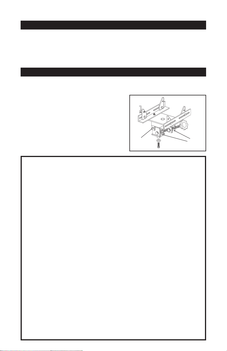
3. Keep adaptor well lubricated at all points shown in
drawing at right.
4. Replace worn or damaged parts with Performance
Tool replacement parts. Be sure that only qualified
personnel perform repairs.
CARE & MAINTENANCE
1
14
14
15
15
16
18
16
14
14
20
15
16
17
10
19
2
11
11
21
12
3
4
5
6
7
8
9
13
13
Oil Oil
6. Connect Platform (1) to Pivot Frame (5) using Pivot Pin (6), Small Snap Rings (12) and
Spacers (21).
7. Bolt on Mounting Bracket Frames (7) and Mounting Brackets (8).
8. Install Chain Hook Assembly (9) and Safety Chains (10).
9. Install Assembled Adaptor onto Service Jack Saddle Frame securing with Bolt (14)
and Washer (20).
ASSEMBLY INSTRUCTIONS (CONTINUED)
